Huawei DCS and Guest OS Red Hat Enterprise Linux 9 Compatibility Test Report

Axians Global
All Right Reserved
1. Overview
1.1 Objective
The objective of this testing report is to test the compatibility between FusionCompute and guest OS.
1.2 Scenario
The test covers the basic functions, reliability, and maintainability of the guest OS.
2. Environment Configuration
2.1 Networking Diagrams for Verification
Figure 2-1 Networking diagram for verifying functions
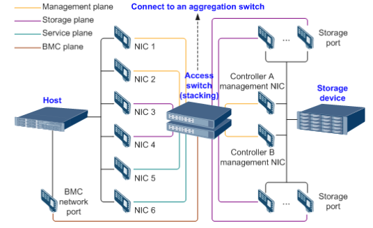

The Windows and Linux hosts are deployed on the Host Server.
2.2 Hardware and Software Configurations
2.2.1 Hardare Configuration
Table 2-1 Hardware configuration
Name | Description | Quantity | Function |
|---|---|---|---|
Host server | x86 server
| 2 | Install FusionCompute and deploy test VMs on FusionCompute. |
10GE switch | CE6800 | 1 | Specifies the network plane on which hosts communicate with storage units on storage devices. Specifies the plane used by user VMs. |
Management switch | GE switch | 1 | Specifies the plane used by the management system to manage all nodes in a unified manner. |
2.2.2 Test Software and Tools
Table 2-2 Test software and tools
Software | Description | Quantity |
|---|---|---|
FusionCompute 8.7.0 | FC virtualization platform | 1 |
Red Hat Enterprise Linux 9.0 | VM OS, Tested Guest OS | 1 |
GPU Card Test Kit | To test the basic functions of the GPU card. | 1 |
SSH client software | SSH terminal connection tool. | 1 |
3. Test Cases
3.1 Guest OS Installation
3.1.1 Installing a Guest OS Image in BIOS Mode
Verify that a guest OS image can be successfully installed in BIOS mode. | |
Networking | Networking diagram for verifying functions |
Prerequisites |
|
Procedure | 1. Create a VM. In the navigation pane of FusionCompute, choose Resource Pool > Create VM. On the displayed page, set OS Type and OS Version to the type and version of the OS to be tested, respectively. In the Configure VM step, click the Options tab and set Boot Firmware to BIOS. (Expected result 1) 2. Select the created VM, choose Configuration > Hardware > CD/DVD-ROM Drive, and mount an image file. (Expected result 2) 3. Forcibly restart the VM and install the OS to be tested on the VM as prompted. (Expected result 3) 4. Select the VM, which is in the stopped state, choose Configuration > Hardware > Graphics Card, select a device type, and start the VM. Repeat the operations for each device type (Cirrus, VGA, and QXL). (Expected result 4) |
Expected Result | 1. When you select the corresponding OS type, the OS to be tested is contained in the OS Version drop-down list. The VM is successfully created. 2. The image file is mounted successfully. 3. The OS is successfully installed, and the VM is started properly. 4. The VM is started successfully. |
Test Result |
2.Select the created VM, choose Configuration > Hardware > CD/DVD-ROM Drive, and mount an image file. (Expected result 2) 3. Forcibly restart the VM and install the OS to be tested on the VM as prompted. (Expected result 3) 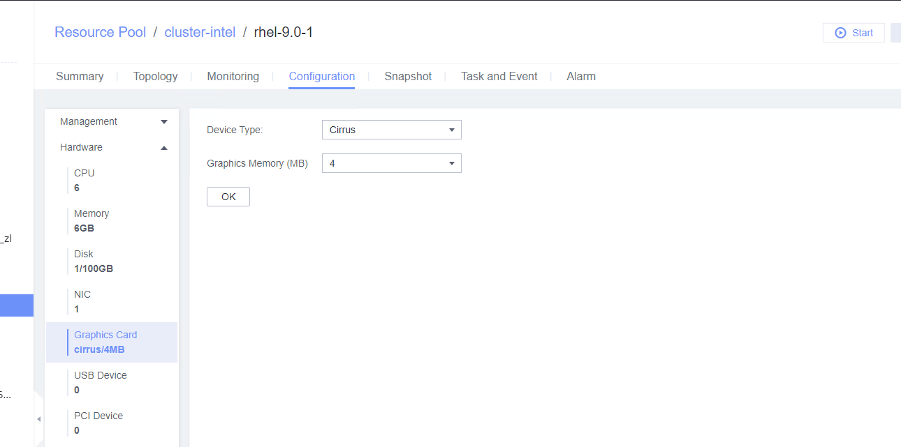 4. Select the VM, which is in the stopped state, choose Configuration > Hardware > Graphics Card, select a device type, and start the VM. Repeat the operations for each device type (Cirrus, VGA, and QXL). (Expected result 4) 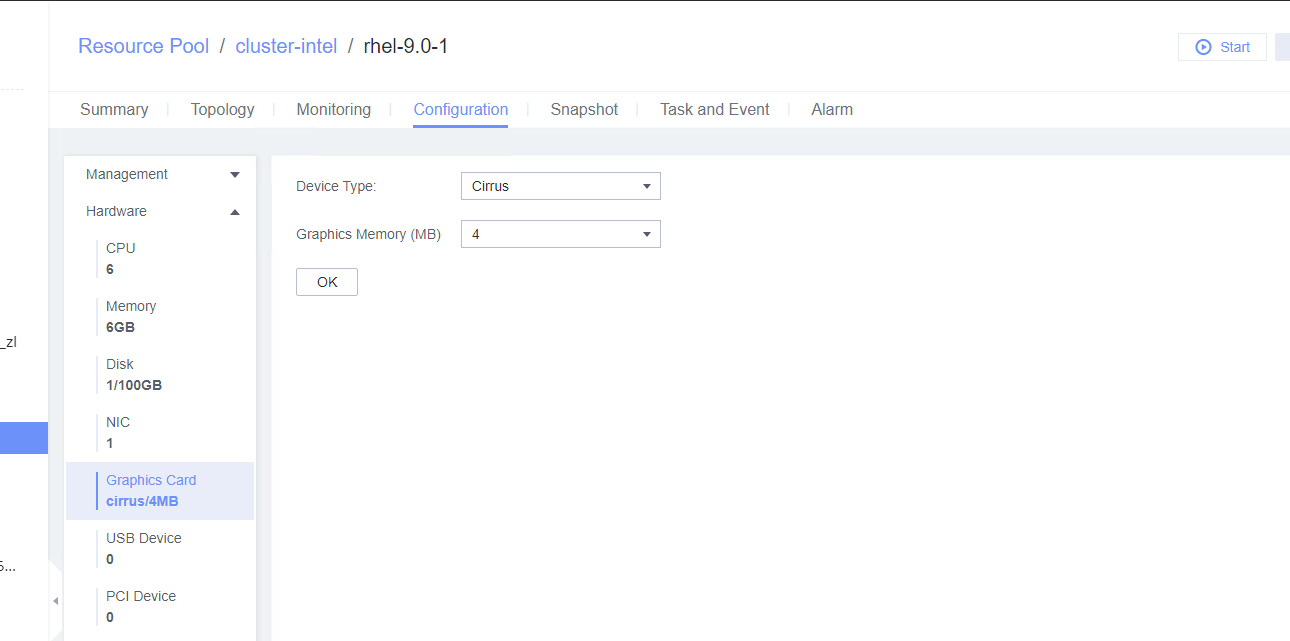  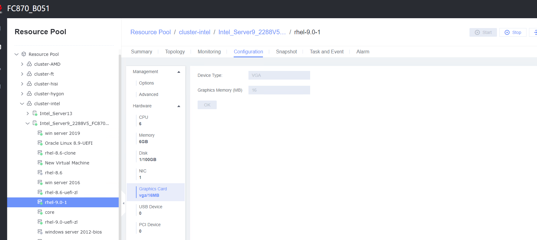 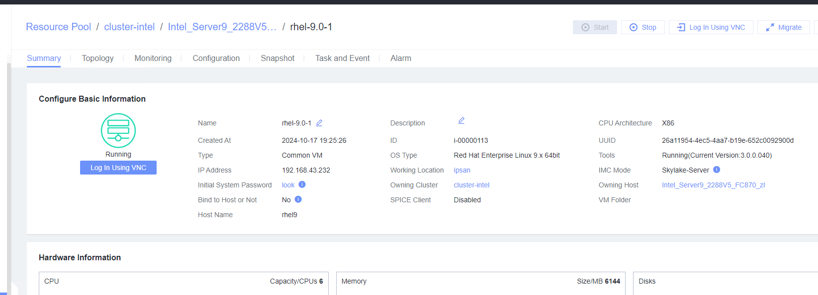 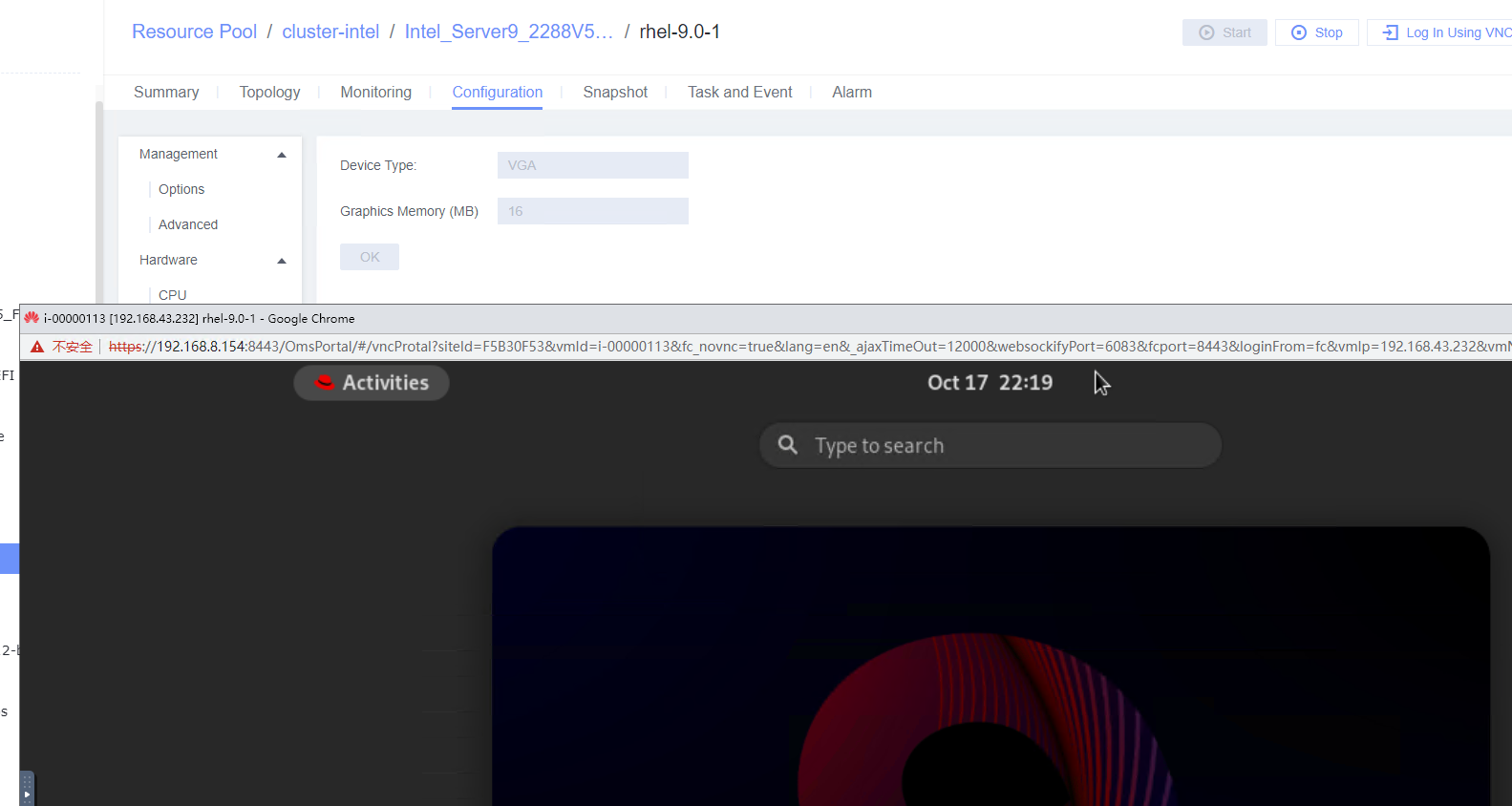 |
Conclusion |
|
Remarks |
3.1.2 Installing a Guest OS Image in UEFI Mode
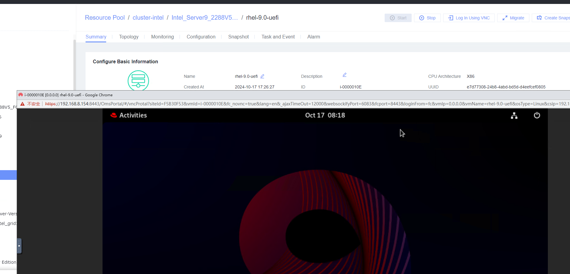
Objective | Verify that a guest OS image can be successfully installed in UEFI mode. |
Networking | Networking diagram for verifying functions |
Prerequisites |
|
Procedure |
2. Select the created VM, choose Configuration > Hardware > CD/DVD-ROM Drive, and mount an image file. 3. Forcibly restart the VM and install the OS to be tested on the VM as prompted. |
Expected Result | 1. When you select the corresponding OS type, the OS to be tested is contained in the OS Version drop-down list. The VM is successfully created. 2. The image file is mounted successfully. 3. The OS is successfully installed, and the VM is started properly. |
Test Result |

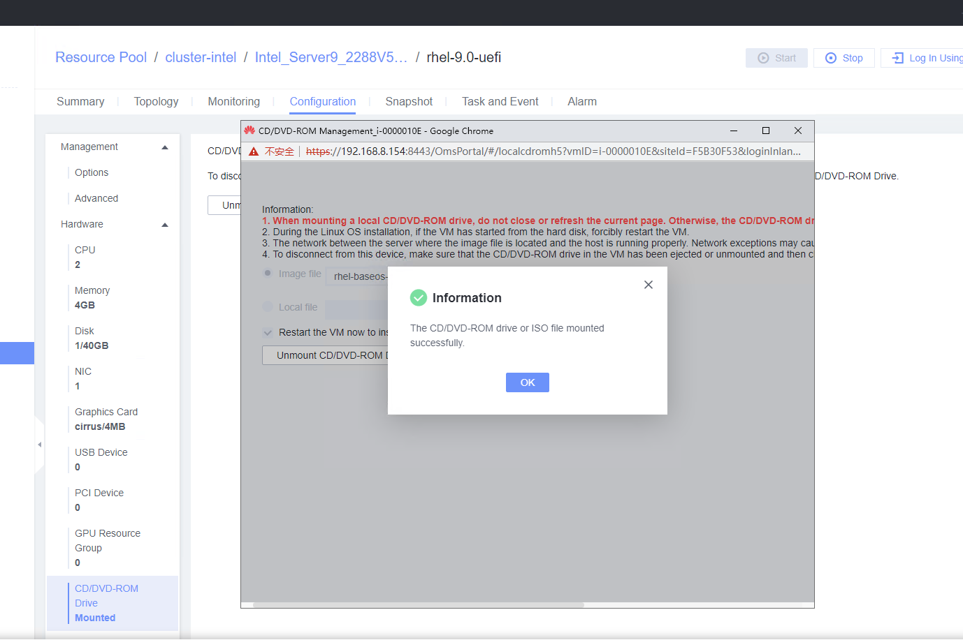 3. Forcibly restart the VM and install the OS to be tested on the VM as prompted. 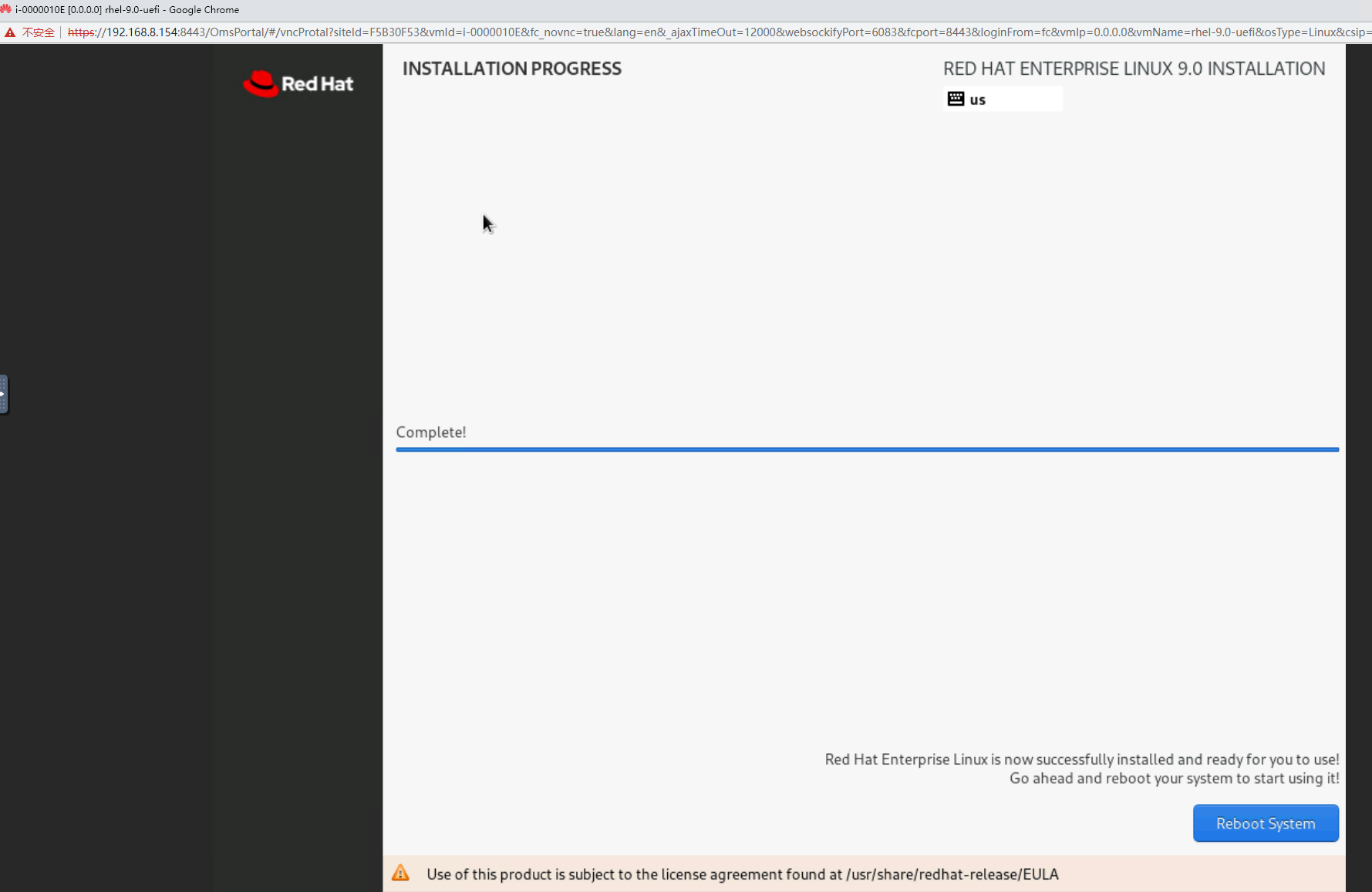 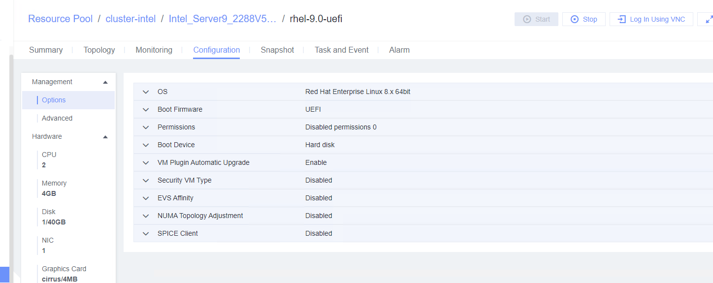
 |
Conclusion | Passed |
Remarks |
3.2 VMTools Installation, Upgrade, and Uninstallation
3.2.1 Installing VMTools
Objective | Verify that VMTools can be successfully installed on a VM. |
Networking | Networking diagram for verifying functions |
Prerequisites | 1. FusionCompute is running properly. 2. A VM whose boot firmware is BIOS and the other VM whose boot firmware is UEFI have been created and the guest OS to be tested has been installed on the VMs. 3. The VMTools package corresponding to the SIA has been prepared. |
Procedure |
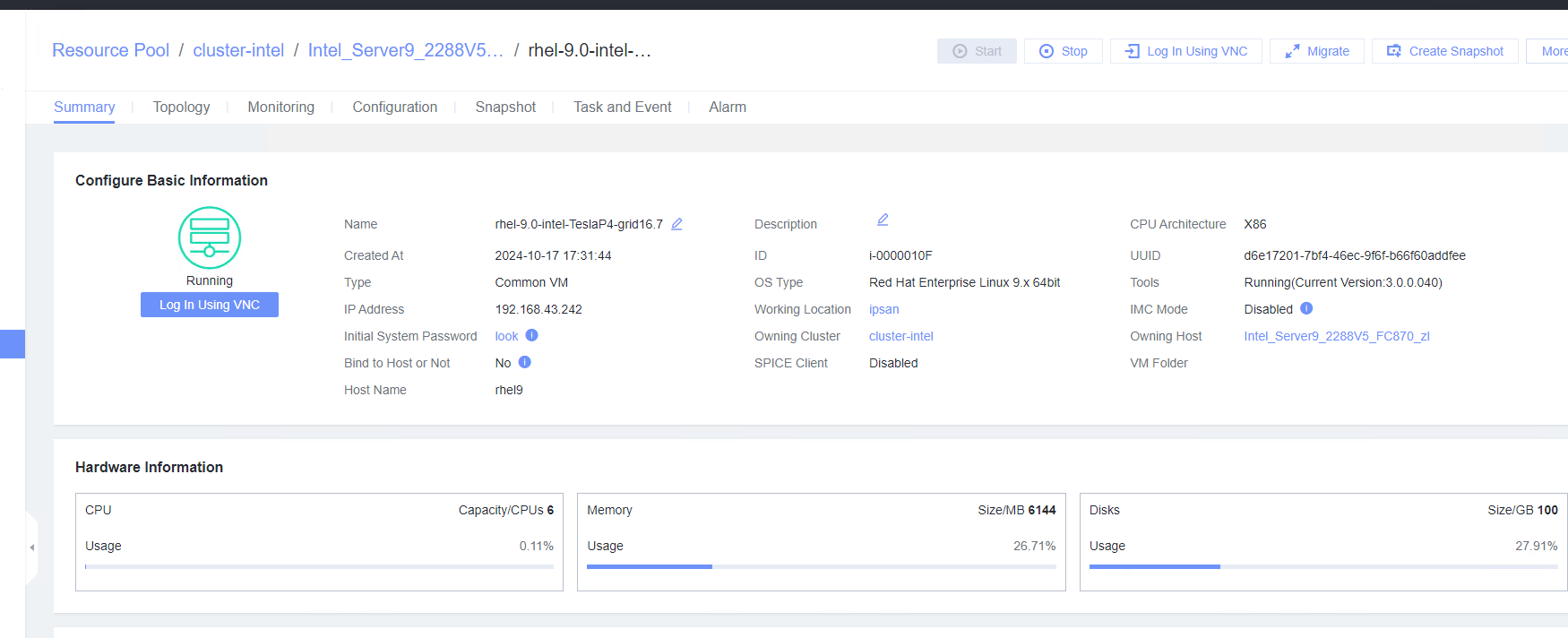
2. Start the VM whose boot firmware is BIOS, and configure the IP address, mask, and gateway for the VM. (Expected result 2) 3. Start the VM whose boot firmware is BIOS, select the VM, and view the VM information on the Monitoring tab page. (Expected result 3) 4. Start the VM whose boot firmware is UEFI, right-click the VM, and choose Tools > Mount Tools from the shortcut menu. For details about how to install Tools, see Operation and Maintenance > Service Management > Virtual Machine Management > Tools Management > Installing Tools in the FusionCompute Product Documentation. (Expected result 1) 5. Start the VM whose boot firmware is UEFI, and configure the IP address, mask, and gateway for the VM. (Expected result 2) 6. Start the VM whose boot firmware is UEFI, select the VM, and view the VM information on the Monitoring tab page. (Expected result 3) |
Expected Result | 1. VMTools is installed successfully. 2. The configured IP address can be used to log in to the VM. 3. The monitoring information about the CPU usage, memory usage, disk usage, disk I/O, and network throughput is displayed properly. |
Test Result |
 2. Start the VM whose boot firmware is BIOS, and configure the IP address, mask, and gateway for the VM. (Expected result 2) 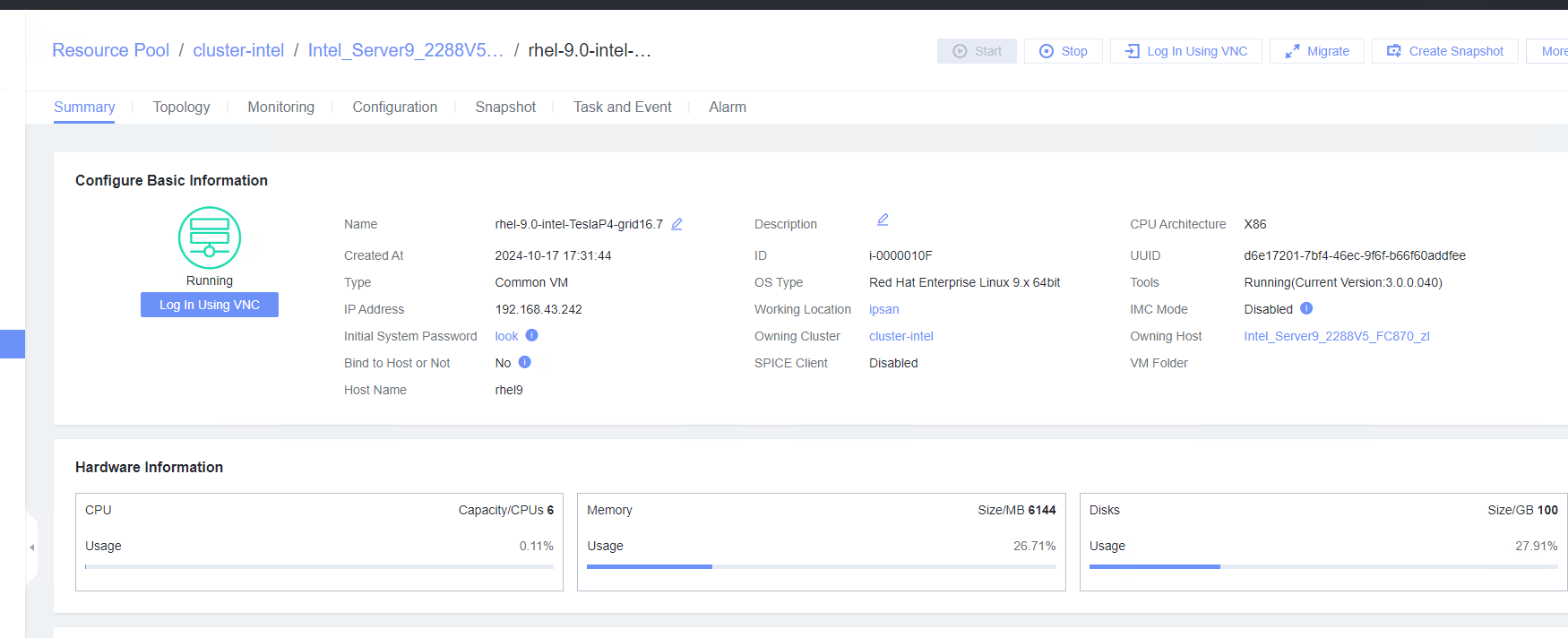 3. Start the VM whose boot firmware is BIOS, select the VM, and view the VM information on the Monitoring tab page. (Expected result 3) 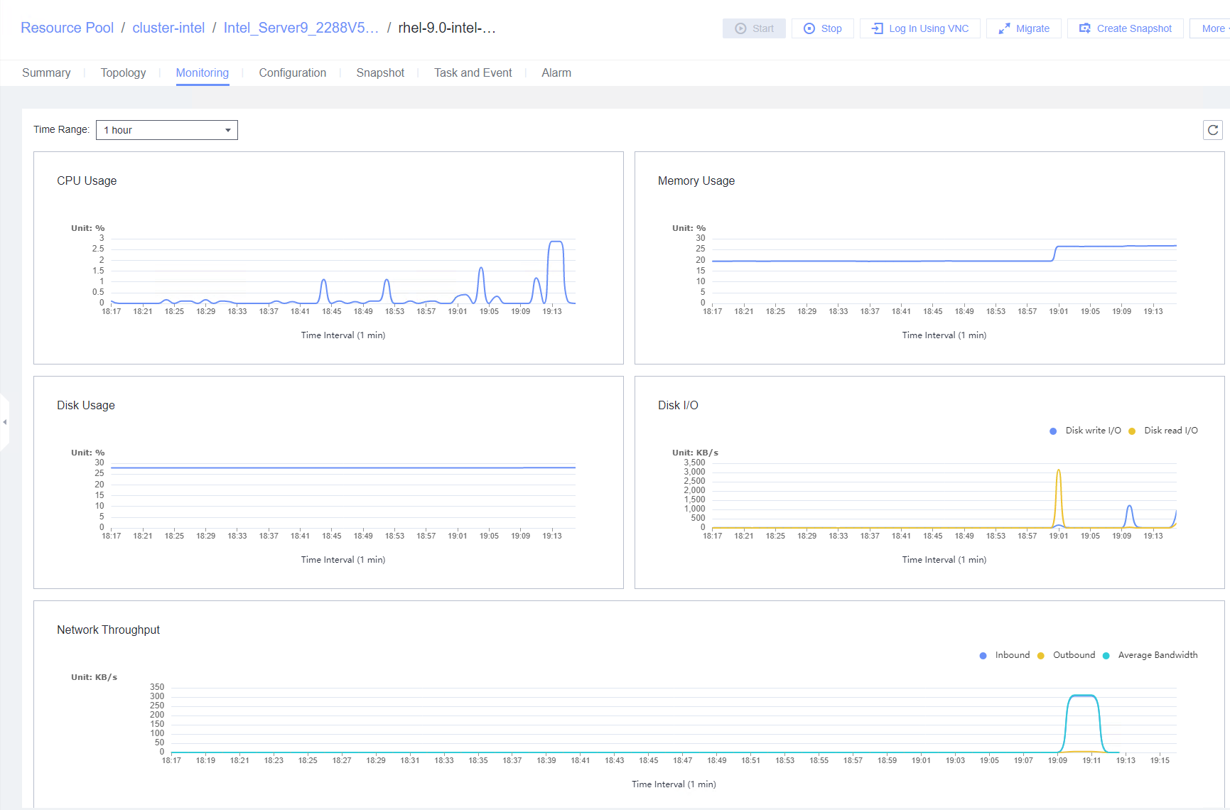 4. Start the VM whose boot firmware is UEFI, right-click the VM, and choose Tools > Mount Tools from the shortcut menu. For details about how to install Tools, see Operation and Maintenance > Service Management > Virtual Machine Management > Tools Management > Installing Tools in the FusionCompute Product Documentation. (Expected result 1)
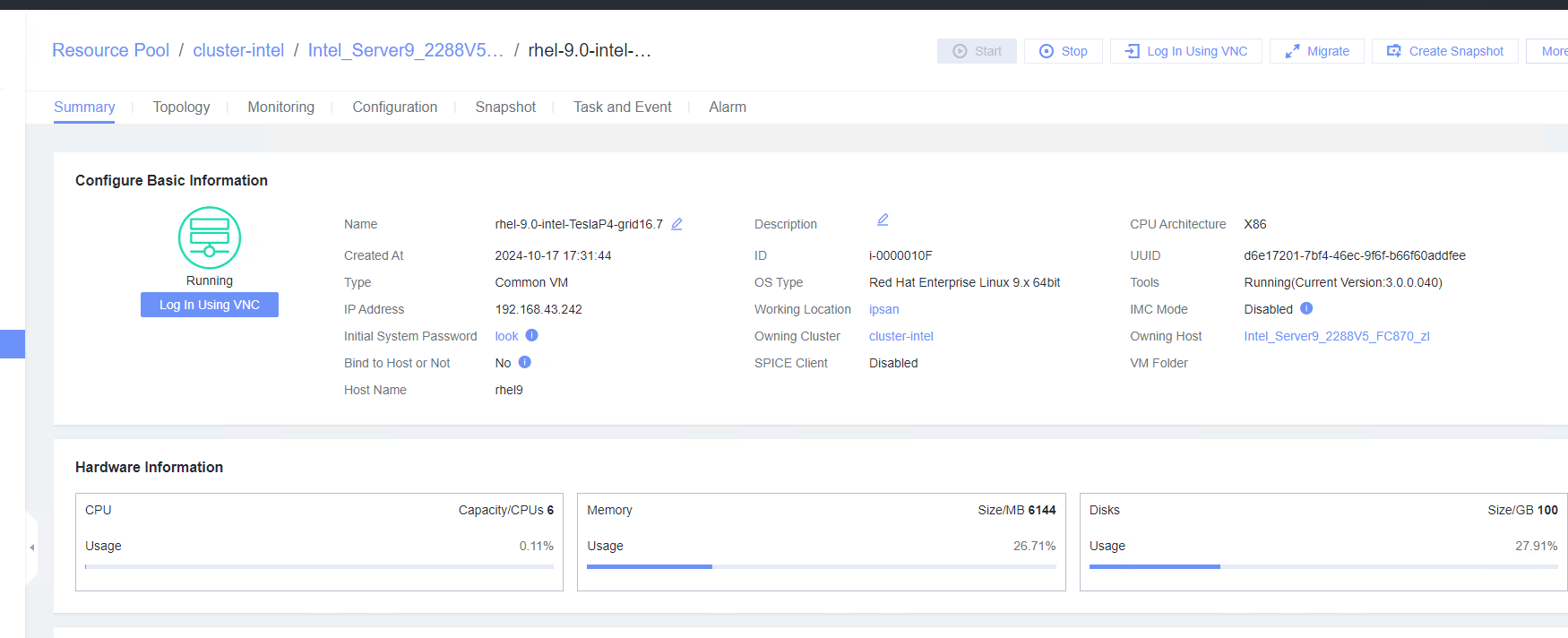 6. Start the VM whose boot firmware is UEFI, select the VM, and view the VM information on the Monitoring tab page. (Expected result 3) 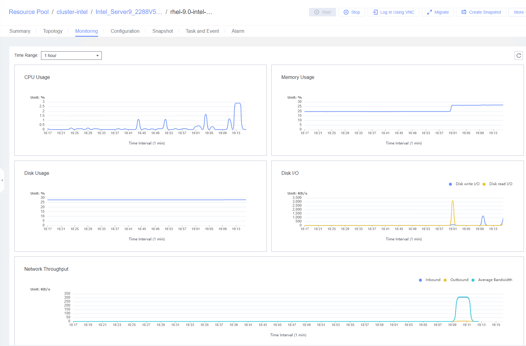 |
Conclusion |
|
Remarks |
3.2.2 Upgrading and Uninstalling VMTools
Objective | Verify that VMTools can be successfully upgraded and uninstalled. |
Networking | Networking diagram for verifying functions |
Prerequisites |
|
Procedure | 1. Install VMTools of an earlier version on the VM. (Expected result 1) 2. Upload the target vmtools-xxx.tar.bz2 installation package to the root directory of the VM, run the tar -xjvf vmtools-xxx.tar.bz2 command to decompress the package, go to the vmtools directory, and run the ./install upgrade command to upgrade VMTools to the target version. (Expected result 2) 3. View the VM information on the Monitoring tab page. (Expected result 3) 4. Right-click the VM and choose Tools > Unmount Tools from the shortcut menu. (Expected result 4) |
Expected Result | 1. VMTools of an earlier version is successfully installed. 2. The VMTools version is upgraded successfully. On the Summary tab page of the VM, the version of the running Tools is the target version. 3. The monitoring information about the CPU usage, memory usage, disk usage, disk I/O, and network throughput is displayed properly. 4. VMTools is uninstalled successfully. The monitoring information about the CPU usage, memory usage, disk usage, disk I/O, and network throughput is not updated with time. |
Test Result | 1. Install VMTools of an earlier version on the VM. (Expected result 1) 5. Right-click the VM and choose Tools > Unmount Tools from the shortcut menu. (Expected result 4)  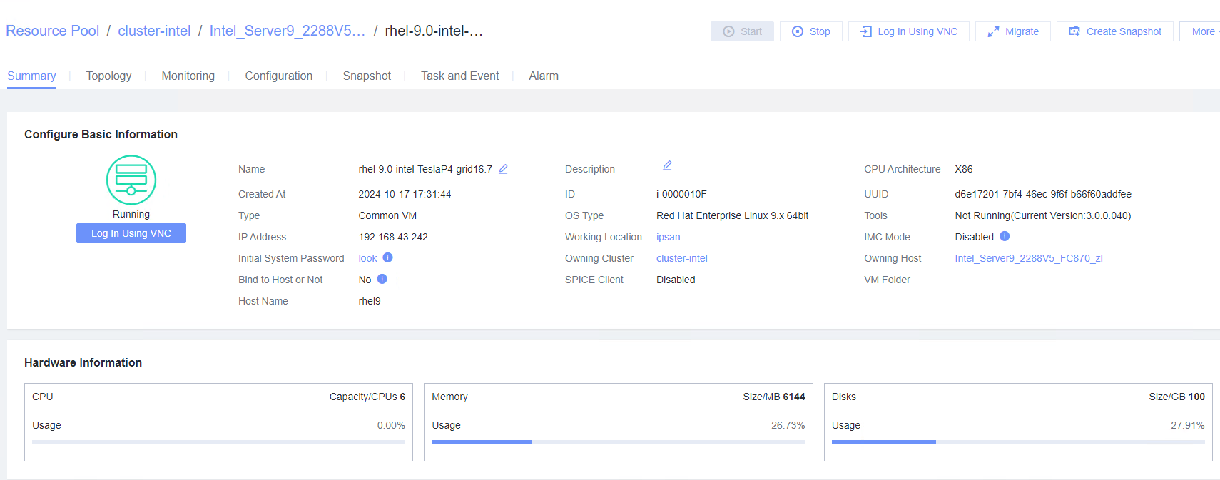 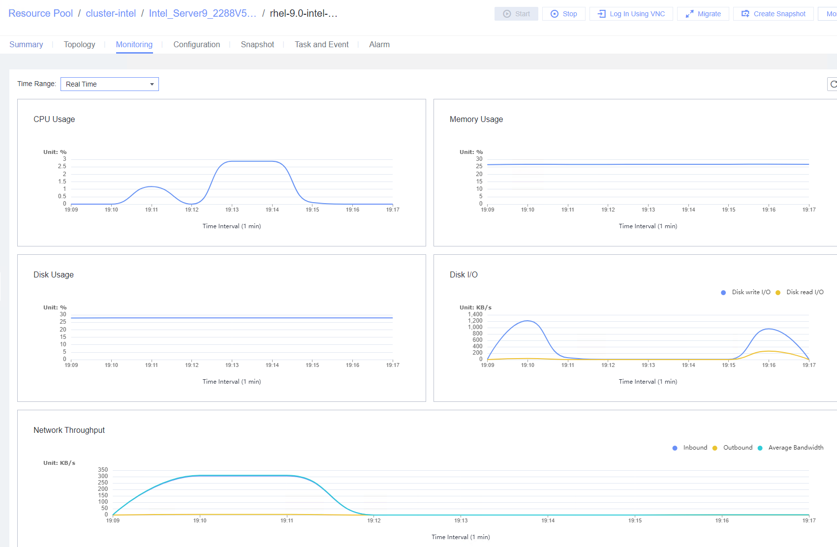 |
Conclusion |
|
Remarks |
3.3 VM Lifecycle Management
3.3.1 Importing or Exporting a VM Template, Converting a VM to a Template, and Cloning a VM
Verify that a VM template can be imported and exported, a VM can be converted to a template, and a VM can be cloned. | |
Networking | Networking diagram for verifying functions |
Prerequisites | 1. FusionCompute is running properly. 2. A guest OS VM to be tested has been created and VMTools corresponding to the SIA has been installed on the VM. |
Procedure |
2. Select the VM template in step 1, convert it to a VM, and start the VM. (Expected result 2) 3. Select the VM in step 2, clone the VM, and select Start VM immediately after creation. (Expected result 3) 4. Right-click the VM in step 2, choose Template > Export as Template, and export the template to a local or shared directory. (Expected result 4) 5. Choose Resource Pool > Resource Pool, import a template, select the template file in step 4, and select the corresponding OS version in the basic configuration. (Expected result 5) |
Expected Result | 1. The VM is successfully converted to a template. 2. The template is successfully converted to a VM, and the VM is started. 3. The cloned VM is started properly. 4. The VM template is exported successfully. 5. The VM template is imported successfully. |
Test Result | 1. Right-click the VM, which is in the stopped state and choose Template > Convert to Template. (Expected result 1)  2. Select the VM template in step 1, convert it to a VM, and start the VM. (Expected result 2)  3. Select the VM in step 2, clone the VM, and select Start VM immediately after creation. (Expected result 3)  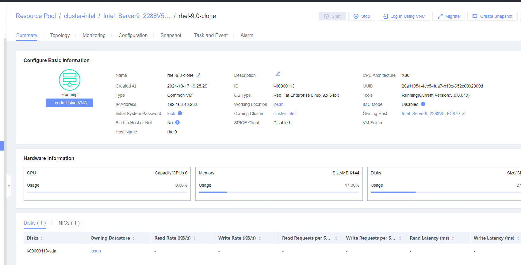 4. Right-click the VM in step 2, choose Template > Export as Template, and export the template to a local or shared directory. (Expected result 4) 5. Choose Resource Pool > Resource Pool, import a template, select the template file in step 4, and select the corresponding OS version in the basic configuration. (Expected result 5) 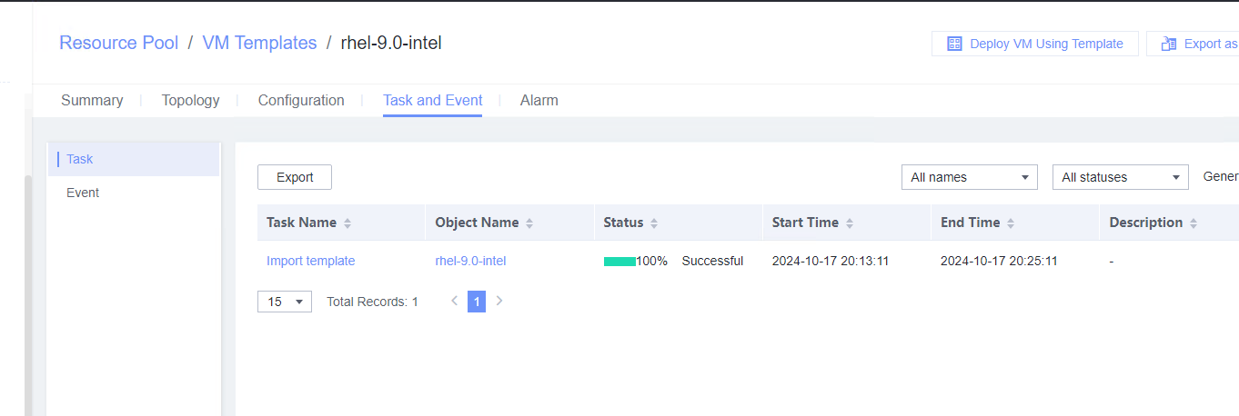 |
Conclusion |
|
Remarks |
3.3.2 Testing the VM Power Supply
Objective | Verify that the VM power supply is normal. |
Networking | Networking diagram for verifying functions |
Prerequisites | 1. FusionCompute is running properly. 2. A guest OS VM to be tested has been created and VMTools corresponding to the SIA has been installed on the VM. |
Procedure | 1. Right-click the VM, choose Power, and select an option. Repeat the operations to start, forcibly restart, stop, and forcibly stop the VM in sequence. After the VM is stopped or forcibly stopped, start the VM. (Expected result 1) 2. Log in to the VM using VNC. (Expected result 2) 3. After the VM is started, open a test file, enter any character string, right-click the VM without exiting the editor, and choose Power > Hibernate. (Expected result 3) 4. Right-click the VM and choose Power > Start. (Expected result 4) |
Expected Result | 1. The VM is restarted and forcibly restarted successfully. After the VM is stopped or forcibly stopped, the VM is started successfully. 2. The login to the VM using VNC is successful, and the mouse and keyboard operations are normal. 3. The VM is hibernated successfully. 4. The VM is started, the file is in the editing state, and the file content in step 3 is not lost. |
Test Result | 1. Right-click the VM, choose Power, and select an option. Repeat the operations to start, forcibly restart, stop, and forcibly stop the VM in sequence. After the VM is stopped or forcibly stopped, start the VM. (Expected result 1) 6. Right-click the VM and choose Power > Start. (Expected result 4)  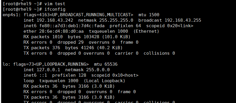 |
Conclusion |
|
Remarks |
3.3.3 Testing the VM Live Migration Function
Objective | Verify that the VM live migration function is normal. |
Networking | Networking diagram for verifying functions |
Prerequisites | 1. FusionCompute has been installed and deployed, and is running properly. You can log in to FusionCompute successfully. 2. A VM that is running properly and has a normal OS is available. Tools has been installed on the VM. 3. A CNA node to which the VM can be migrated exists in the system, and the backend storage of the VM is SAN storage. |
Procedure | 1. In the address box of a local browser, enter http://VRM floating IP address to log in to FusionCompute. (Expected result 1) 2. When the VM is running, click the VM tab, select the VM to be migrated (VM1 on host CNA1). Right-click the VM and choose Migrate from the shortcut menu. Set Migration Mode to Change Host and Datastore, and select a destination host and a target datastore. (Expected result 2) 3. Choose System Management > Tasks and Logs > Task Center to view the status of the live migration task. Wait until the task is complete. (Expected result 3) 4. Check the host to which VM1 belongs. (Expected result 4) 5. During the migration, ping the IP address of the VM. (Expected result 5) |
Expected Result | 1. The login to FusionCompute is successful. 2. The VM live migration task is created successfully. 3. On the Task Center page that is displayed, the migration task is complete. 4. VM1 is running properly on host CNA2 (not host CNA1). 5. During the VM migration, the continuous ping tests are successful and no obvious packet loss occurs. |
Test Result | 1. In the address box of a local browser, enter http://VRM floating IP address to log in to FusionCompute. (Expected result 1) 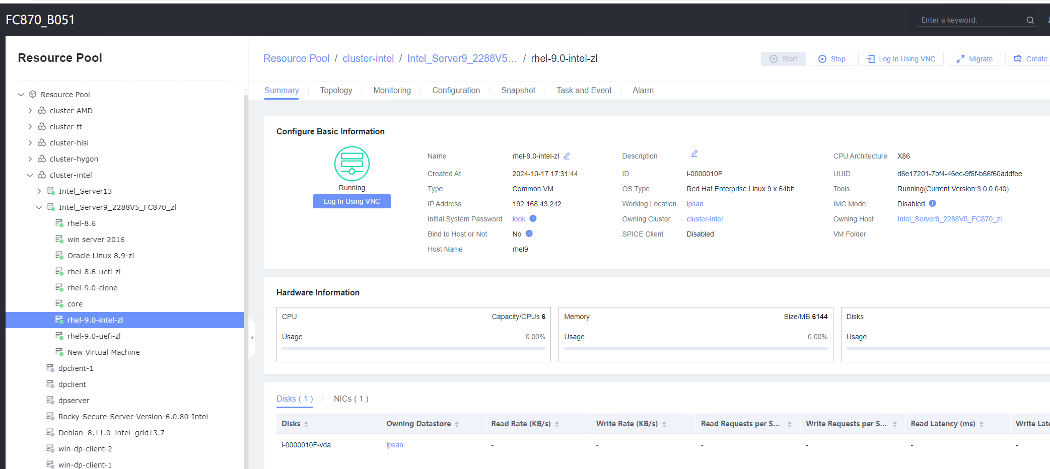 2. When the VM is running, click the VM tab, select the VM to be migrated (VM1 on host CNA1). Right-click the VM and choose Migrate from the shortcut menu. Set Migration Mode to Change Host and Datastore, and select a destination host and a target datastore. (Expected result 2) 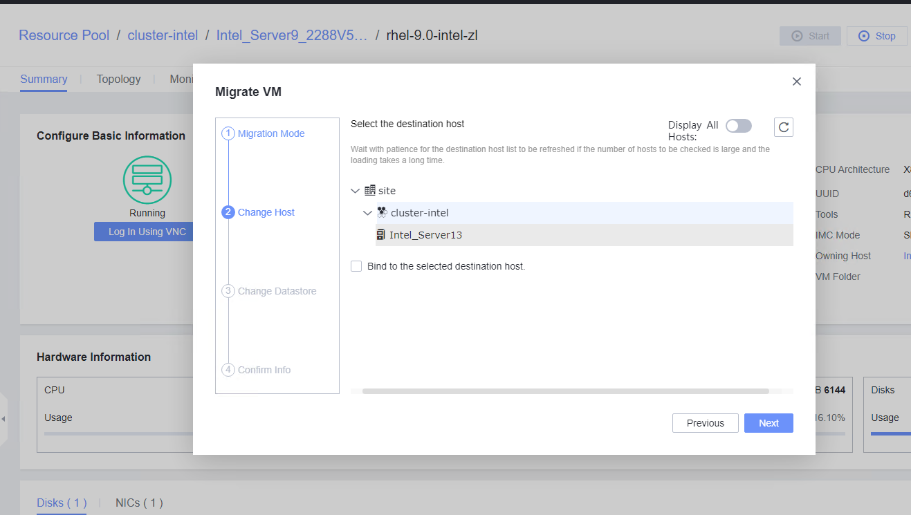 3. Choose System Management > Tasks and Logs > Task Center to view the status of the live migration task. Wait until the task is complete. (Expected result 3)  4. Check the host to which VM1 belongs. (Expected result 4) 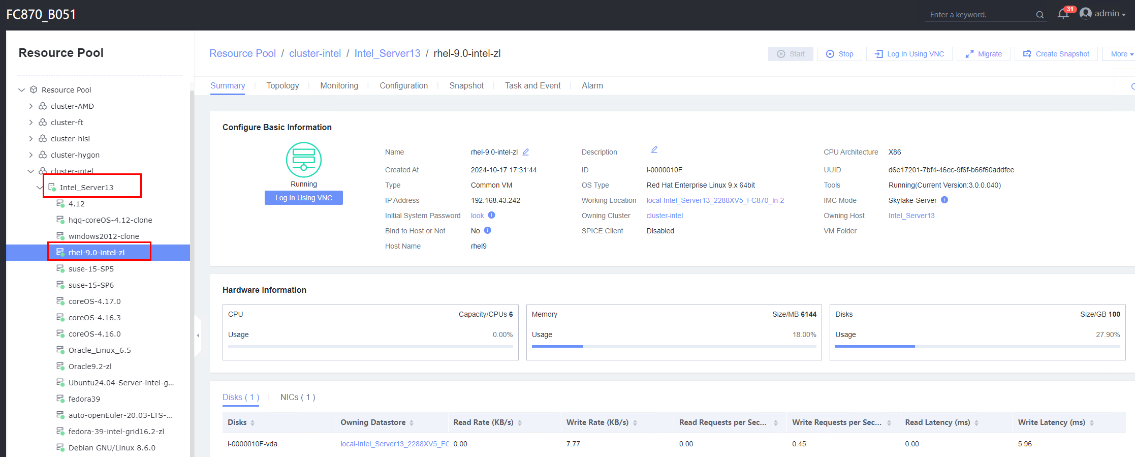 5. During the migration, ping the IP address of the VM. (Expected result 5) 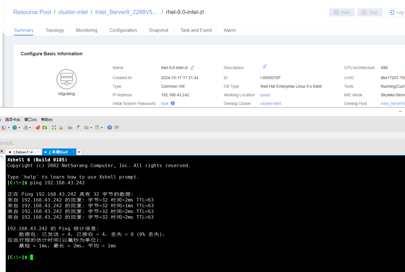
|
Conclusion |
|
Remarks |
3.3.4 Deleting a VM
Objective | Verify that a VM can be deleted. |
Networking | Networking diagram for verifying functions |
Prerequisites | 1. FusionCompute is running properly. 2. A guest OS VM to be tested has been created and VMTools corresponding to the SIA has been installed on the VM. |
Procedure | 1. Right-click the VM and choose Delete > Delete. (Expected result 1) 2. Right-click the VM and choose Delete > Safely Delete. (Expected result 1) |
Expected Result | 1. The VM is deleted successfully. |
Test Result | 1. Right-click the VM and choose Delete > Delete. (Expected result 1)  2. Right-click the VM and choose Delete > Safely Delete. (Expected result 1) 
|
Conclusion |
|
Remarks |
3.4 Disk Hot Swap
3.4.1 Attaching a Disk Whose Bus Type Is SCSI to or Detaching It from a Running VM
Objective | Verify that a disk whose bus type is SCSI can be attached to or detached from a running VM. |
Networking | Networking diagram for verifying functions |
Prerequisites | 1. FusionCompute has been installed and deployed and the system is running properly. You can log in to FusionCompute successfully. 2. You have logged in to FusionCompute and a corresponding datastore is available. 3. A VM with a normal OS is running properly. |
Procedure | 1. Select the VM, which is in the running state, choose Configuration > Hardware > Disk > Attach Disk. On the displayed page, click Create and Attach Disk, set Bus Type to SCSI, select the created disk, and click OK. (Expected result 1) 2. Select the VM and choose Configuration > Disk to view the disk information. (Expected result 2) 3. Log in to the VM, run the lsblk command to query the newly added disk, format the disk, and mount the disk to the specified directory. Then, create files on the disk, modify the files, and delete the files from the disk. (Expected result 3) 4. Select the disk attached to the VM in step 1 and expand the VM disk capacity. (Expected result 4) 5. After expanding the VM disk capacity and formatting the disk, perform read and write operations on the disk. (Expected result 5) 6. Select the VM, which is in the running state, choose Configuration > Hardware > Disk, select the disk created in step 1, and choose More > Detach. Note: For some OSs, you may need to shut down the VM before detaching the disk. (Expected result 6) 7. Log in to the VM and run the lsblk command to query the disk information. (Expected result 7) |
Expected Result | 1. The disk is successfully attached to the VM. 2. Information about the newly attached disk is displayed on the disk page. 3. Files can be created on the disk, modified, and deleted from the disk. 4. The disk capacity is expanded successfully. 5. The read and write operations on the disk after capacity expansion are normal. 6. No information about the detached disk is displayed on the disk page. 7. No information about the detached disk is displayed in the command output. |
Test Result | 1. Select the VM, which is in the running state, choose Configuration > Hardware > Disk > Attach Disk. On the displayed page, click Create and Attach Disk, set Bus Type to SCSI, select the created disk, and click OK. (Expected result 1) 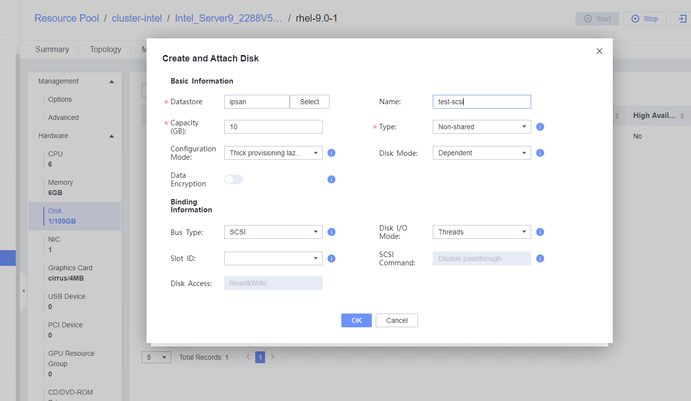
2. Select the VM and choose Configuration > Disk to view the disk information. (Expected result 2) 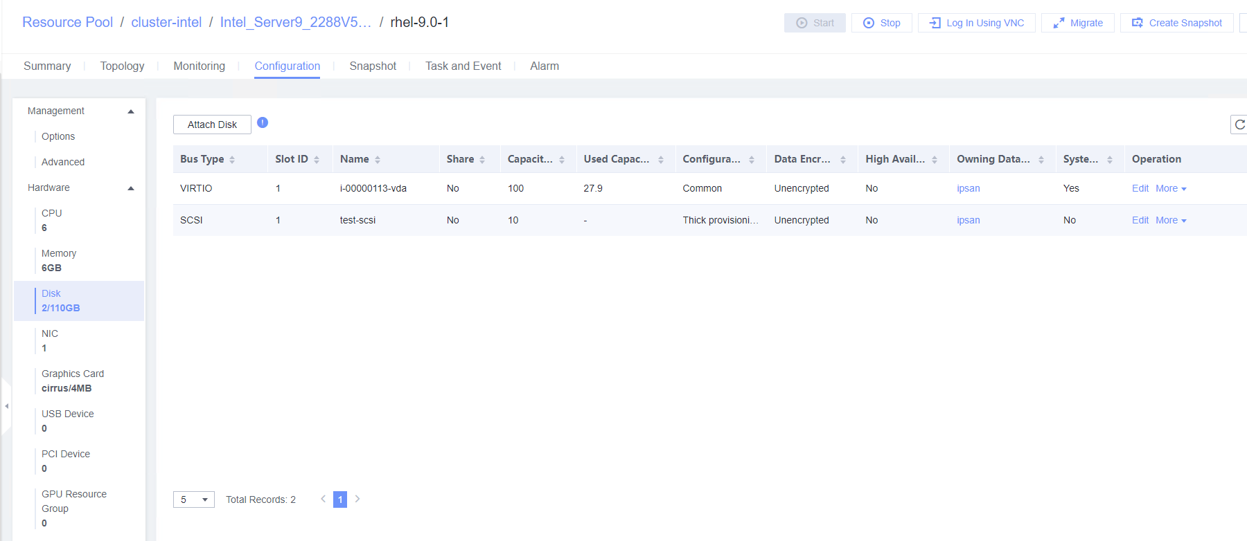 3. Log in to the VM, run the lsblk command to query the newly added disk, format the disk, and mount the disk to the specified directory. Then, create files on the disk, modify the files, and delete the files from the disk. (Expected result 3) 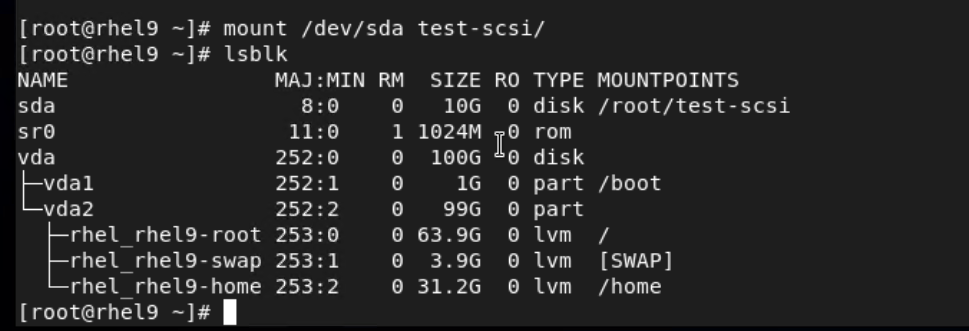
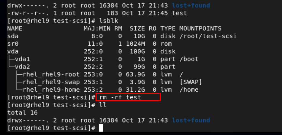 4. Select the disk attached to the VM in step 1 and expand the VM disk capacity. (Expected result 4) 
5. After expanding the VM disk capacity and formatting the disk, perform read and write operations on the disk. (Expected result 5) 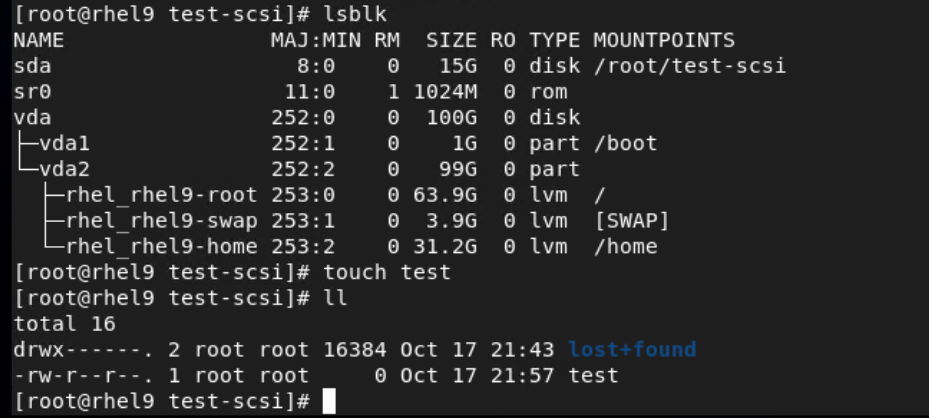 6. Select the VM, which is in the running state, choose Configuration > Hardware > Disk, select the disk created in step 1, and choose More > Detach. Note: For some OSs, you may need to shut down the VM before detaching the disk. (Expected result 6) 
7. Log in to the VM and run the lsblk command to query the disk information. (Expected result 7)  |
Conclusion |
|
Remarks |
3.4.2 Attaching a Disk Whose Bus Type Is VIRTIO to or Detaching It from a Running VM
Objective | Verify that a disk whose bus type is VIRTIO can be attached to or detached from a running VM. |
Networking | Networking diagram for verifying functions |
Prerequisites |
|
Procedure | 1. Select the VM, which is in the running state, choose Configuration > Hardware > Disk > Attach Disk. On the displayed page, click Create and Attach Disk, set Bus Type to VIRTIO, select the created disk, and click OK. (Expected result 1) 2. Select the VM and choose Configuration > Disk to view the disk information. (Expected result 2) 3. Log in to the VM, run the lsblk command to query the newly added disk, format the disk, and mount the disk to the specified directory. Then, create, modify, and delete files on the new disk. (Expected result 3) 4. Select the VM, which is in the running state, choose Configuration > Hardware > Disk, select the disk created in step 1, and choose More > Detach. Note: For some OSs, you may need to shut down the VM before detaching the disk. (Expected result 4) 5. Log in to the VM and run the lsblk command to query the disk information. (Expected result 5) |
Expected Result | 1. The disk is successfully attached to the VM. 2. Information about the newly attached disk is displayed on the disk page. 3. Files can be created on the disk, modified, and deleted from the disk. 4. No information about the detached disk is displayed on the disk page. 5. No information about the detached disk is displayed in the command output. |
Test Result | 1. Select the VM, which is in the running state, choose Configuration > Hardware > Disk > Attach Disk. On the displayed page, click Create and Attach Disk, set Bus Type to VIRTIO, select the created disk, and click OK. (Expected result 1)  |
Conclusion |
|
Remarks |
3.5 VM NIC Operations
3.5.1 Adding a NIC to or Deleting It from a Running VM
Objective | Verify that a NIC can be added to or deleted from a running VM. |
Networking | Networking diagram for verifying functions |
Prerequisites |
|
Procedure | 1. Select the VM, which is in the running state, choose Configuration > Hardware > NIC > Add NIC, select a port group under common network connection, and click OK. Run the ifconfig –a/ip link show command to view the VM NIC information. (Expected result 1) 2. Configure the IP address and mask of the new NIC through DHCP or manual configuration. (Expected result 2) 3. Select the VM, which is in the running state, choose Configuration > Hardware > NIC > Operation > Delete NIC, and run the ifconfig –a/ip link show command to view the VM NIC information. (Expected result 3) |
Expected Result | 1. The NIC is successfully added to the VM, and the new NIC information can be queried. 2. After the IP address is configured successfully, the IP address can be pinged locally. 3. The NIC is deleted successfully, and the deleted NIC cannot be queried on the VM. |
Test Result | 1. Select the VM, which is in the running state, choose Configuration > Hardware > NIC > Add NIC, select a port group under common network connection, and click OK. Run the ifconfig –a/ip link show command to view the VM NIC information. (Expected result 1) 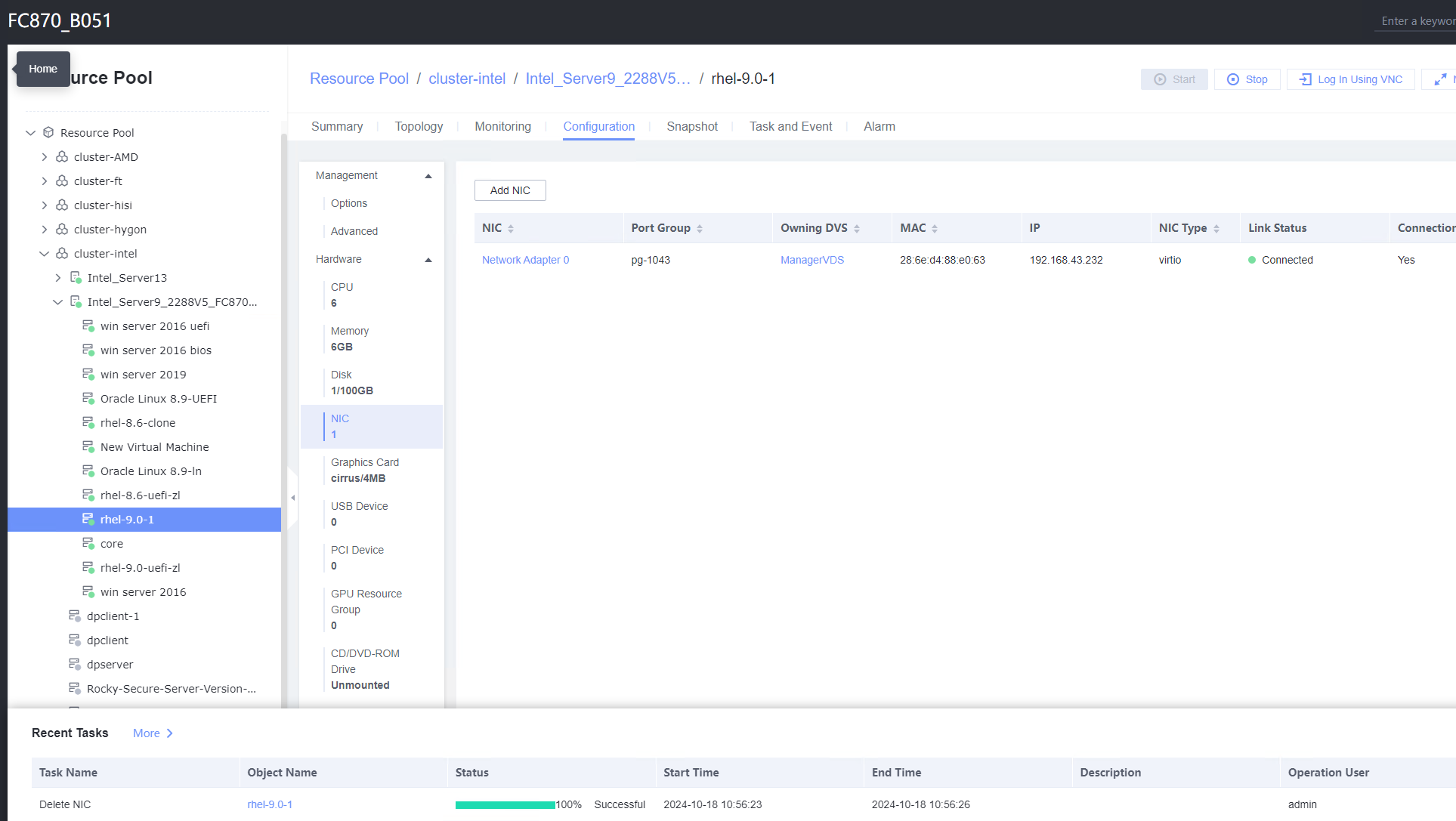 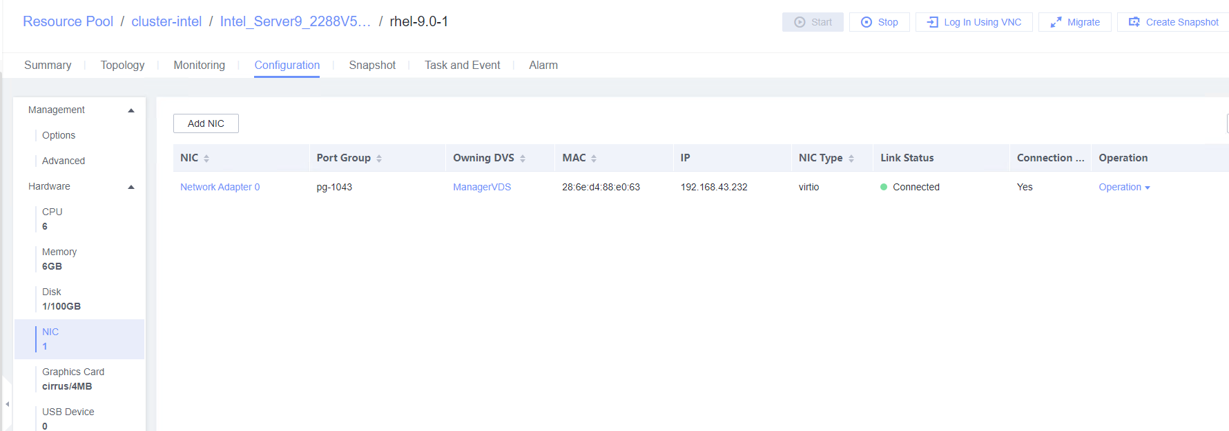 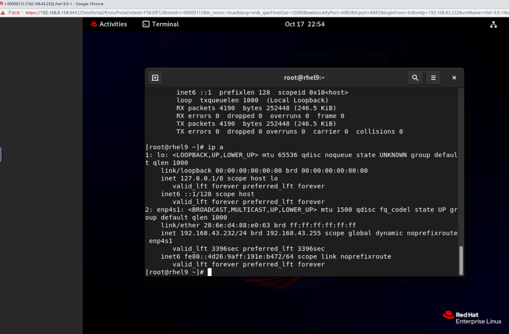 |
Conclusion | Passed |
Remarks |
3.5.2 Testing the PCI Passthrough NIC of a VM
Objective | Verify that the PCI passthrough NIC of a VM is normal. |
Networking | Networking diagram for verifying functions |
Prerequisites |
|
Procedure | 1. Select the VM, which is in the stopped state, choose Configuration > Hardware > PCI Device > Bind PCI Device, select a NIC that supports PCI passthrough, and click OK. Start the VM and run the ifconfig –a/ip link show command to view the VM NIC information. (Expected result 1) 2. Configure the IP address and mask of the new NIC through DHCP or manual configuration. (Expected result 2) 3. Select the VM, which is in the stopped state, choose Configuration > Hardware > PCI Device, select the NIC added in step 1, unbind the NIC, and start the VM. Then, run the ifconfig –a/ip link show command to view the VM NIC information. (Expected result 3) |
Expected Result | 1. The NIC is successfully added to the VM, and the new NIC information can be queried. 2. After the IP address is configured successfully, the IP address can be pinged locally. 3. The NIC is deleted successfully, and the deleted NIC cannot be queried on the VM. |
Test Result | 1. Select the VM, which is in the stopped state, choose Configuration > Hardware > PCI Device > Bind PCI Device, select a NIC that supports PCI passthrough, and click OK. Start the VM and run the ifconfig –a/ip link show command to view the VM NIC information. (Expected result 1) 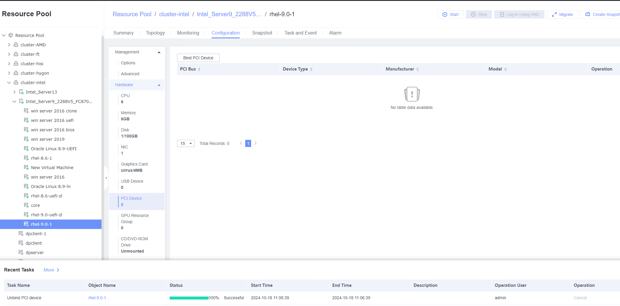 |
Conclusion |
|
Remarks |
3.5.3 Testing the VM NIC in SR-IOV Passthrough Mode
Objective | Verify that a VM can properly use the NIC in SR-IOV passthrough mode. |
Networking | Networking diagram for verifying functions |
Prerequisites |
|
Procedure | 1. Choose Resource Pool > Host > Configuration > Network > Physical NIC. Select the corresponding network port, for example, eth1, click Change Switch Mode to switch to the SR-IOV mode, set the number of VFs, and click OK. (Expected result 1) 2. Choose Resource Pool > Network > Create DVS. In the displayed dialog box, create a DVS named SR-IOV1, set the switch type to SR-IOV-enabled, select Add Uplinks and Add VLAN Pool, and click Next. Select the network port for which the SR-IOV mode is configured in previous step and click Next. Then, click Add, enter a VLAN range from 2 to 4094, click Next, and click OK. (Expected result 2) 3. Choose Resource Pool > Network, select SR-IOV1 created in the previous step, click the Port Groups tab, and click Add to add port group pg1. Set Port Type to Access, configure other parameters, and click Next. Set Connection Mode to VLAN, set the VLAN ID, and click Next. After confirming all information, click OK. (Expected result 3) 4. In the resource pool, locate the VM created in step 1. When the VM is stopped, click the VM name and choose Configuration > Hardware > NIC. Then, locate the NIC and choose Operation > Modify Port Group, select SR-IOV1 created in step 2 for the DVS and pg1 for the port group, and click OK. (Expected result 4) 5. Start the VM, configure the IP address and mask of the new NIC through DHCP or manual configuration, and run the ifconfig –a/ip link show command to view the VM NIC information. (Expected result 5) |
Expected Result | 1. The switch mode of the port is SR-IOV. 2. User-mode DVS SR-IOV1 is successfully created. 3. Port group pg1 is created. 4. The NIC is added successfully. 5. The new NIC is queried. After the IP address is configured successfully, the IP address can be pinged locally. |
Test Result | 1. Choose Resource Pool > Host > Configuration > Network > Physical NIC. Select the corresponding network port, for example, eth1, click Change Switch Mode to switch to the SR-IOV mode, set the number of VFs, and click OK. (Expected result 1) 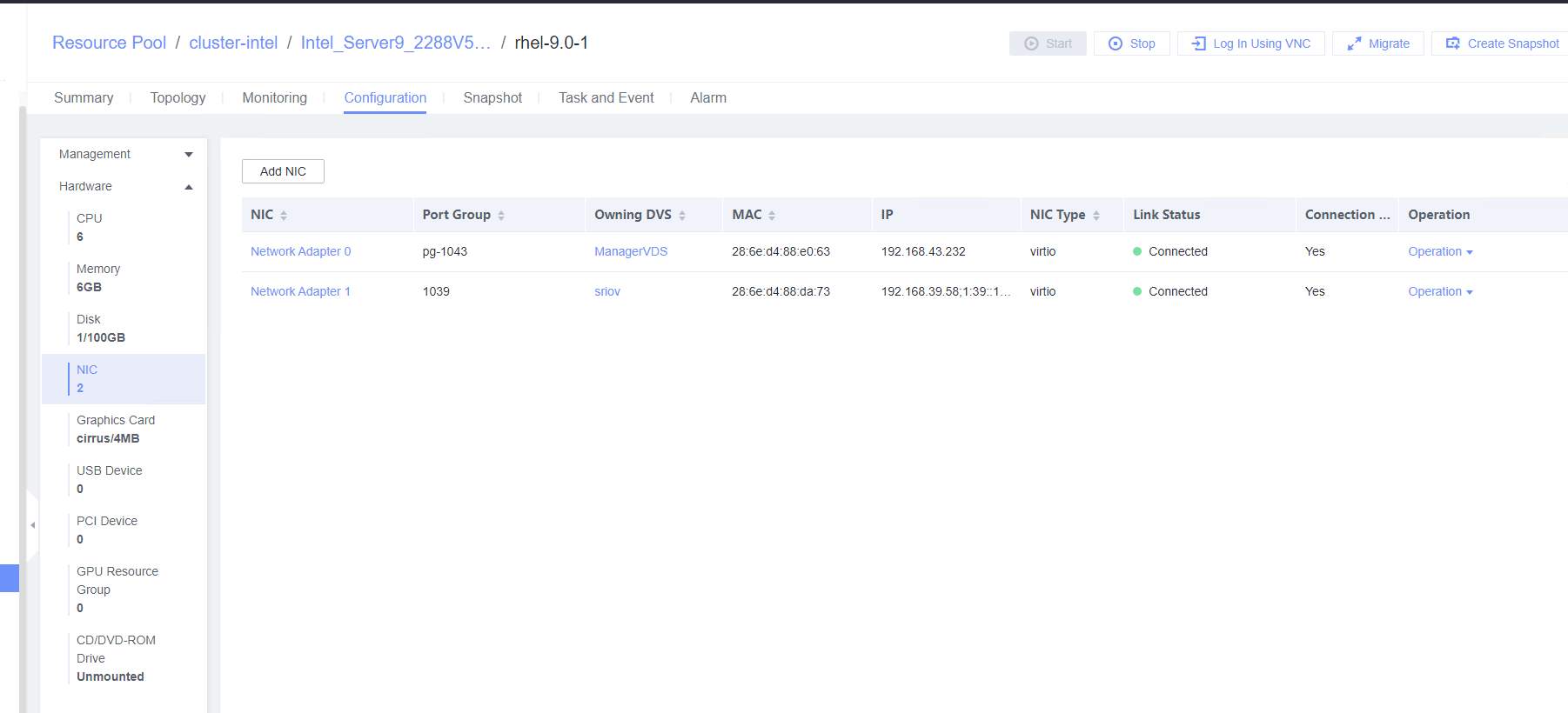 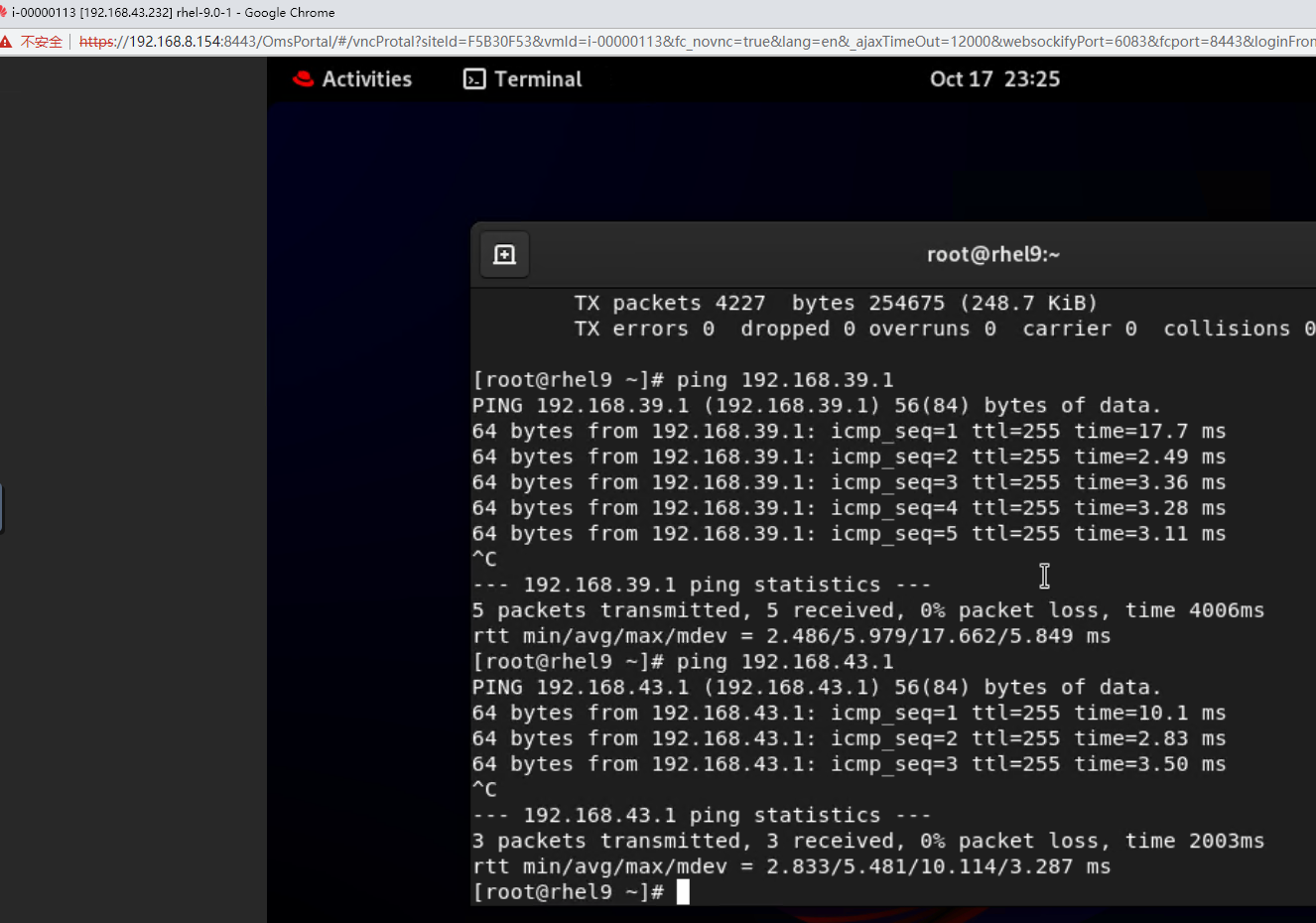 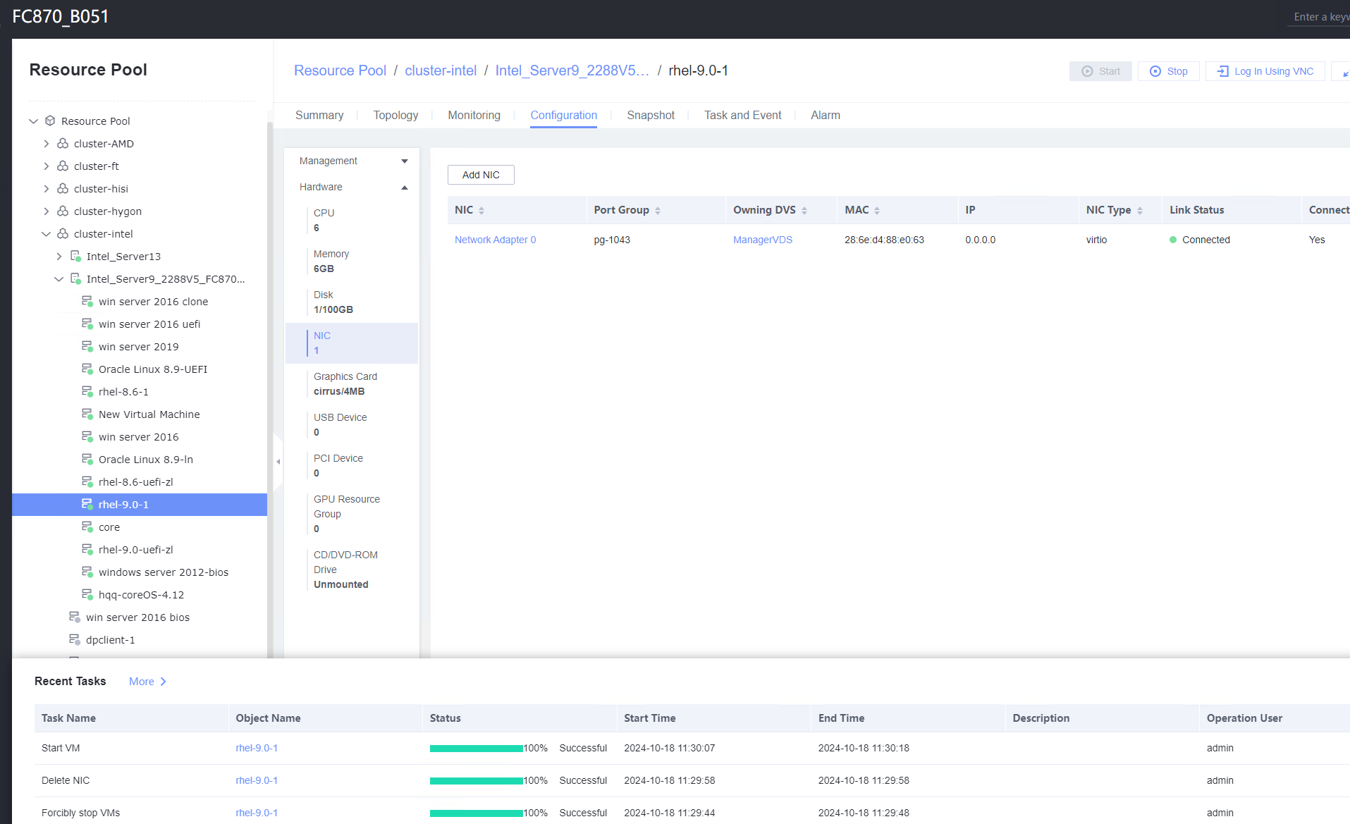 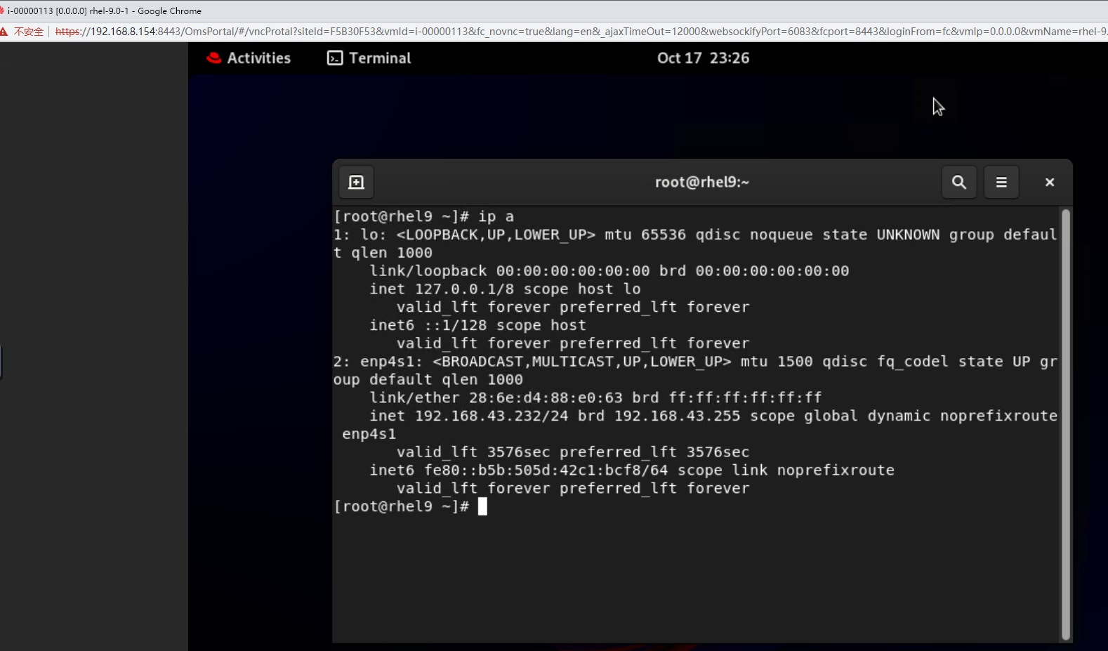 |
Conclusion |
|
Remarks |
3.5.4 Testing the Network Configuration of the VM NICs
Objective | Verify that the network configuration of the VM NICs is normal. |
Networking | Networking diagram for verifying functions |
Prerequisites |
|
Procedure | 1. Add two NICs to the VM. 2. Configure a static IPv4 address for the first NIC. (Expected result 1) 3. Configure a static IPv6 address for the second NIC. (Expected result 2) |
Expected Result | 1. The static IPv4 address is configured successfully, and the static IPv4 gateway can be pinged from the VM. 2. The static IPv6 address and dynamic IPv6 routing are successfully configured. The static IPv6 gateway can be pinged from the VM. |
Test Result | 1. Add two NICs to the VM. 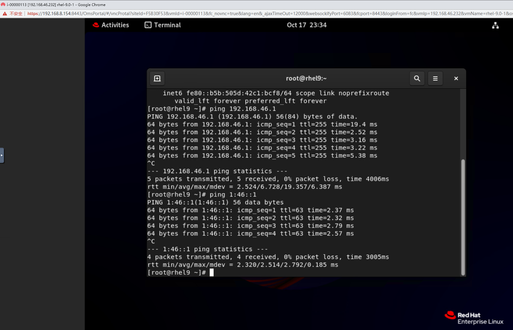 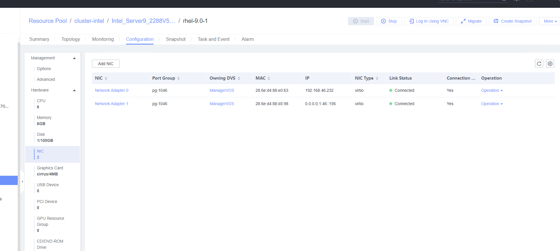 3. Configure a static IPv6 address for the second NIC. (Expected result 2) 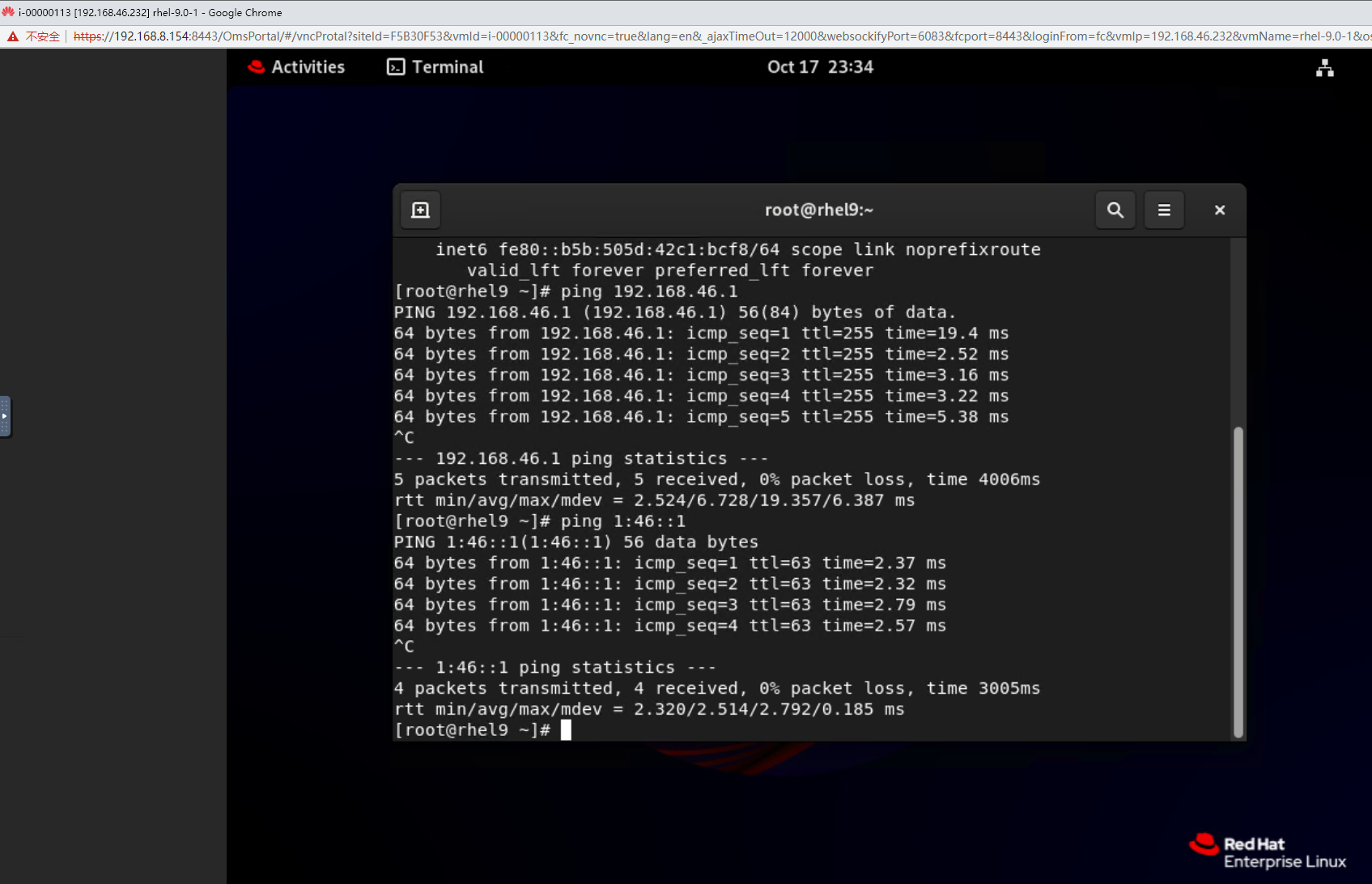 |
Conclusion |
|
Remarks |
3.6 Adding CPU and Memory to a VM
3.6.1 Adjusting the CPU and Memory Specifications of a Running VM
Objective | Verify that the CPU and memory specifications of a running VM can be adjusted. |
Networking | Networking diagram for verifying functions |
Prerequisites | 1. FusionCompute is running properly. 2. A VM has been created and is running properly. 3. In FusionCompute 8.3.0 and later versions, x86 servers support online CPU and memory expansion. In FusionCompute 8.5.0 and later versions, Arm servers support online CPU and memory expansion. Note: The CPU and memory configurations take effect without the need to reset the VM. |
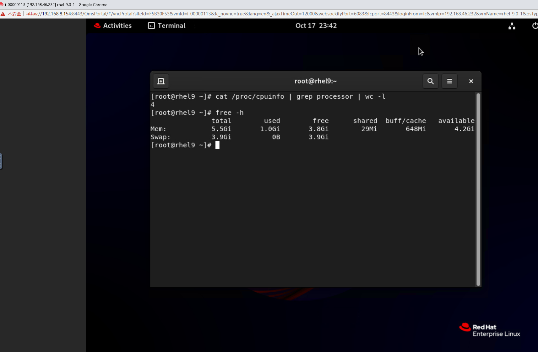
Procedure | 1. Select the VM, choose Configuration > Hardware, and set the CPU and memory parameters to larger values. 2. Refresh the FusionCompute page. Select the VM and choose Configuration > Hardware > CPU and Configuration > Hardware > Memory to view the specifications after adjustment. 3. Log in to the VM using VNC, and run the cat /proc/cpuinfo |more and free –h commands to view the CPU and memory information, respectively. |
Expected Result | 1. The CPU and memory parameters are successfully set to larger values. 2. The CPU and memory parameters after expansion are displayed. 3. The VM OS is running properly. The CPU and memory information displayed in the background is the same as that on the FusionCompute page. |
Test Result | 1. Select the VM, choose Configuration > Hardware, and set the CPU and memory parameters to larger values. 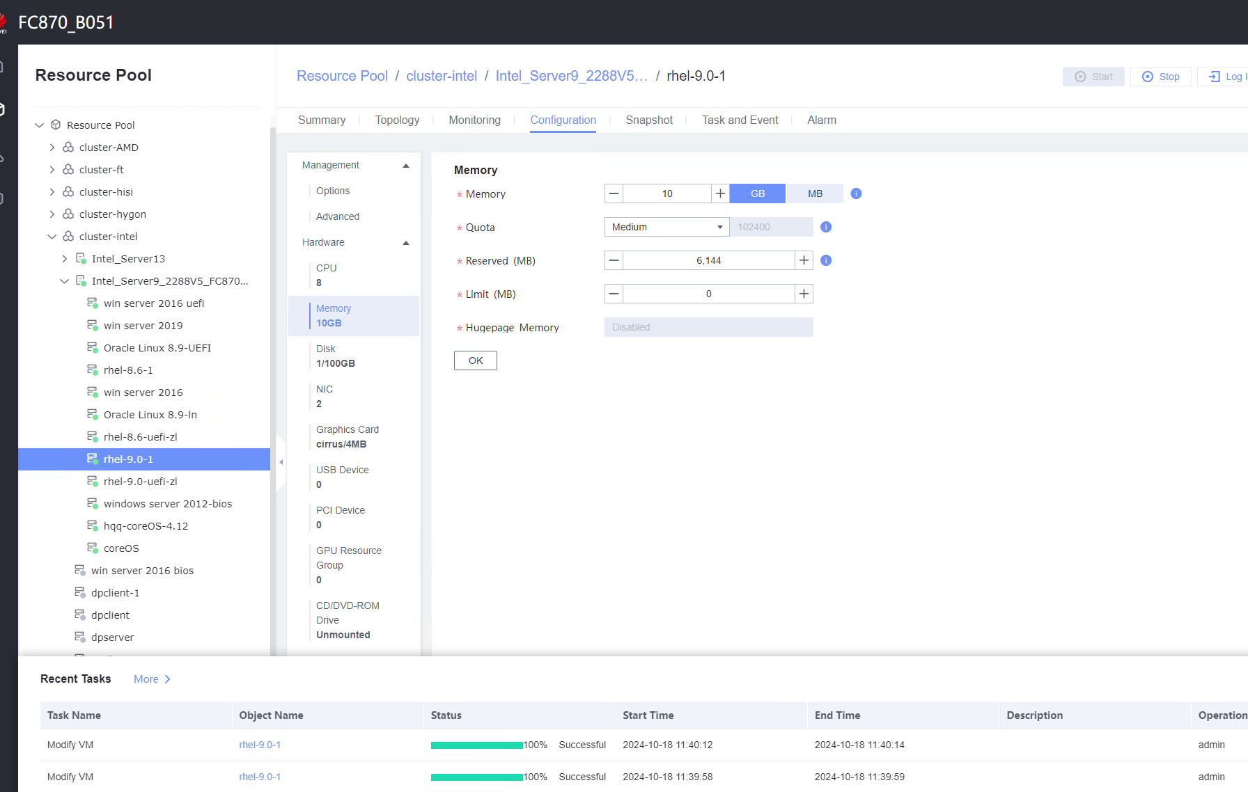 2. Refresh the FusionCompute page. Select the VM and choose Configuration > Hardware > CPU and Configuration > Hardware > Memory to view the specifications after adjustment. 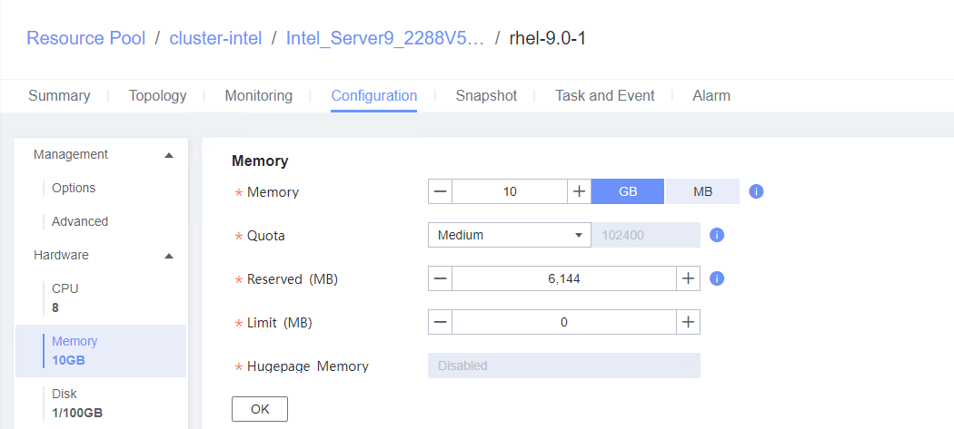 3. Log in to the VM using VNC, and run the cat /proc/cpuinfo |more and free –h commands to view the CPU and memory information, respectively. 
 |
Conclusion |
|
Remarks |
3.6.2 Configuring the CPU and Memory and Restarting a VM for the Configuration to Take Effect
Objective | Verify that the CPU and memory configuration takes effect after a VM is restarted. |
Networking | Networking diagram for verifying functions |
Prerequisites | 1. FusionCompute is running properly. 2. A VM has been created and is running properly. 3. In FusionCompute 8.3.0 and later versions, x86 servers support online CPU and memory expansion. In FusionCompute 8.5.0 and later versions, Arm servers support online CPU and memory expansion. Note: This test case is executed only when the test in section 2.7.1 fails. |
Procedure | 1. Select the VM, choose Configuration > Hardware, set the CPU and memory parameters to larger values, and reset the VM. 2. Refresh the FusionCompute page. Select the VM and choose Configuration > Hardware > CPU and Configuration > Hardware > Memory to view the specifications after adjustment. 3. Log in to the VM using VNC, and run the cat /proc/cpuinfo |more and free –h commands to view the CPU and memory information, respectively. 4. Select the VM, choose Configuration > Hardware, set the CPU and memory parameters to smaller values, and reset the VM. 5. Refresh the FusionCompute page. Select the VM and choose Configuration > Hardware > CPU and Configuration > Hardware > Memory to view the specifications after adjustment. 6. Log in to the VM using VNC, and run the cat /proc/cpuinfo |more and free –h commands to view the CPU and memory information, respectively. |
Expected Result | 1. The CPU and memory parameters are successfully set to larger values. 2. The CPU and memory parameters after expansion are displayed. 3. The VM OS is running properly. The CPU and memory information displayed in the background is the same as that on the FusionCompute page. 4. The CPU and memory parameters are successfully set to smaller values. 5. The CPU and memory parameters after reduction are displayed. 6. The VM OS is running properly. The CPU and memory information displayed in the background is the same as that on the FusionCompute page. |
Test Result | 1. Select the VM, choose Configuration > Hardware, set the CPU and memory parameters to larger values, and reset the VM. 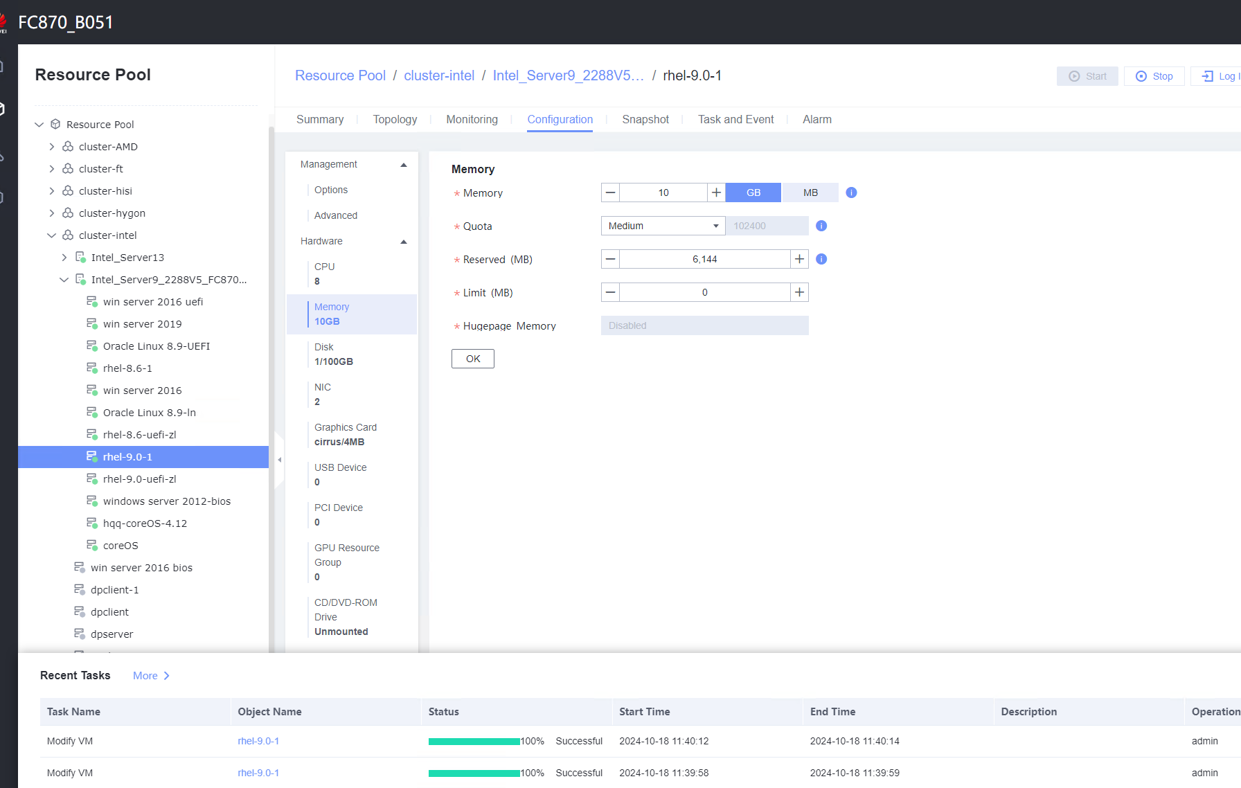 2. Refresh the FusionCompute page. Select the VM and choose Configuration > Hardware > CPU and Configuration > Hardware > Memory to view the specifications after adjustment. 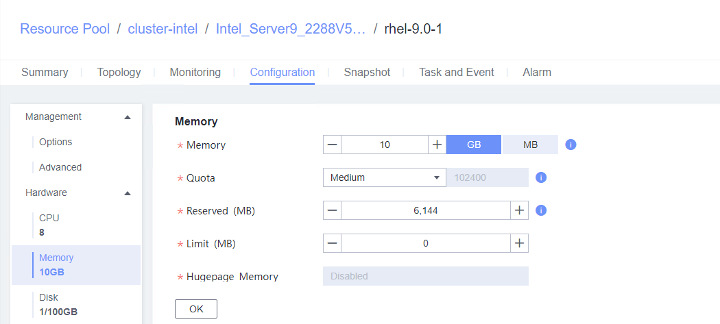 3. Log in to the VM using VNC, and run the cat /proc/cpuinfo |more and free –h commands to view the CPU and memory information, respectively.  4. Select the VM, choose Configuration > Hardware, set the CPU and memory parameters to smaller values, and reset the VM. 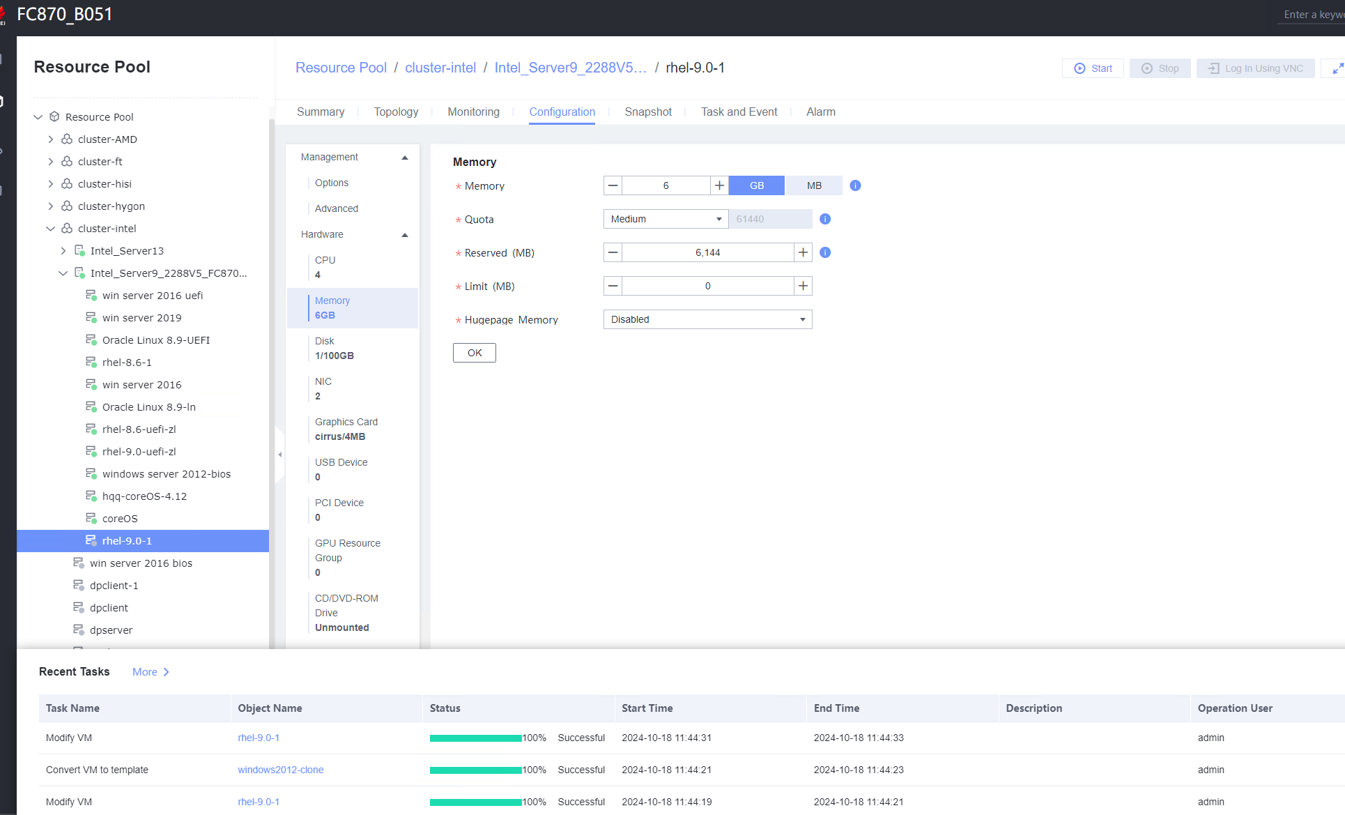 5. Refresh the FusionCompute page. Select the VM and choose Configuration > Hardware > CPU and Configuration > Hardware > Memory to view the specifications after adjustment.  6. Log in to the VM using VNC, and run the cat /proc/cpuinfo |more and free –h commands to view the CPU and memory information, respectively. 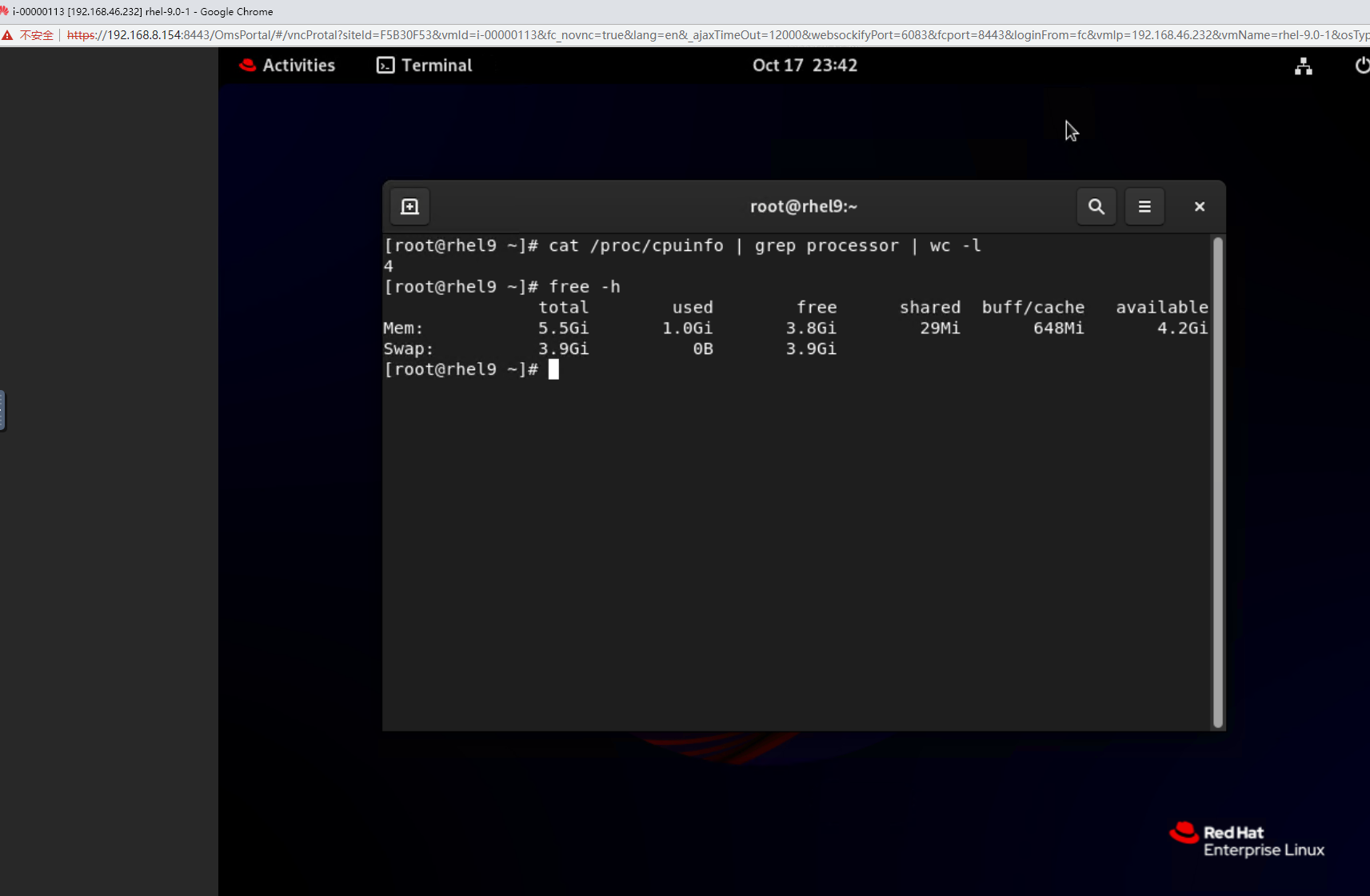 |
Conclusion |
|
Remarks |
3.7 VM Clock Policy
3.7.1 Testing the VM Clock Synchronization
Objective | Verify that the VM clock synchronization is normal. |
Networking | Networking diagram for verifying functions |
Prerequisites | 1. FusionCompute has been installed and deployed, and is running properly. You can log in to FusionCompute successfully. 2. The free clock function is enabled on the VM. |
Procedure |
2. Select the VM, which is in the stopped state, choose Configuration > Management > Advanced > Clock Synchronization Policy > Settings. In the displayed dialog box, select Synchronize with host clock, and click OK. Then, start the VM. (Expected result 1) 3. Log in to the VM and check the VM time and host time. (Expected result 2) |
Expected Result | 1. Clock synchronization is configured successfully. 2. The VM time is the same as the host time. |
Test Result | 2. Select the VM, which is in the stopped state, choose Configuration > Management > Advanced > Clock Synchronization Policy > Settings. In the displayed dialog box, select Synchronize with host clock, and click OK. Then, start the VM. (Expected result 1) 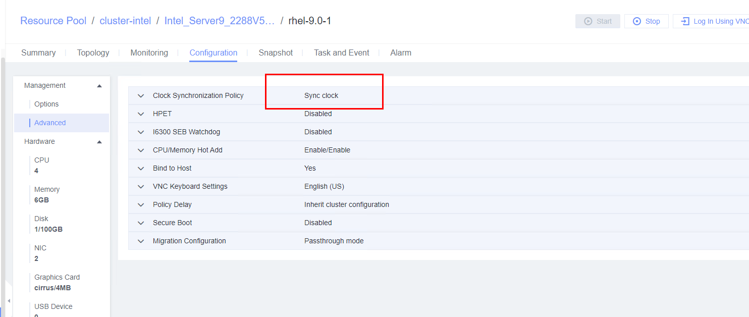 3. Log in to the VM and check the VM time and host time. (Expected result 2)
 VM: 
|
Conclusion |
|
Remarks |
3.7.2 Testing the Free Clock Function of the VM
Objective | Verify that the free clock function of the VM is normal. |
Networking | Networking diagram for verifying functions |
Prerequisites | 1. FusionCompute has been installed and deployed, and is running properly. You can log in to FusionCompute successfully. 2. Clock synchronization is enabled on the VM, and the host time is consistent with the VM time. |
Procedure | 1. Select the VM, which is in the stopped state, choose Configuration > Management > Advanced > Clock Synchronization Policy > Settings. In the displayed dialog box, deselect Synchronize with host clock, and click OK. Then, start the VM. (Expected result 1) 2. Log in to the VM and change the VM time to make the time difference between the VM and the host is 8 hours. (Expected result 2) 3. Log in to the host using SSH and run the /sbin/hwclock –systohc command to set the free time persistence. (Expected result 3) 4. Restart the VM and check the time on the VM. (Expected result 4) |
Expected Result | 1. The free clock is configured successfully. 2. The VM time is changed successfully. The time difference between the VM and the host is 8 hours. 3. The free time persistence is set successfully. 4. The time difference between the VM and the host is 8 hours. |
Test Result | 1. Select the VM, which is in the stopped state, choose Configuration > Management > Advanced > Clock Synchronization Policy > Settings. In the displayed dialog box, deselect Synchronize with host clock, and click OK. Then, start the VM. (Expected result 1)  2. Log in to the VM and change the VM time to make the time difference between the VM and the host is 8 hours. (Expected result 2) 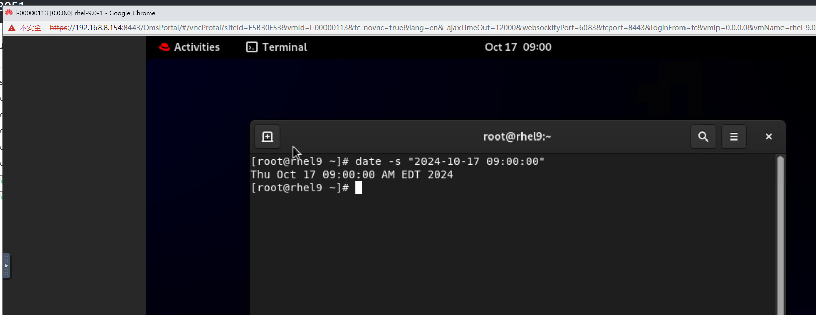 3. Log in to the host using SSH and run the /sbin/hwclock –systohc command to set the free time persistence. (Expected result 3)  4. Restart the VM and check the time on the VM. (Expected result 4)  Host:  VM: 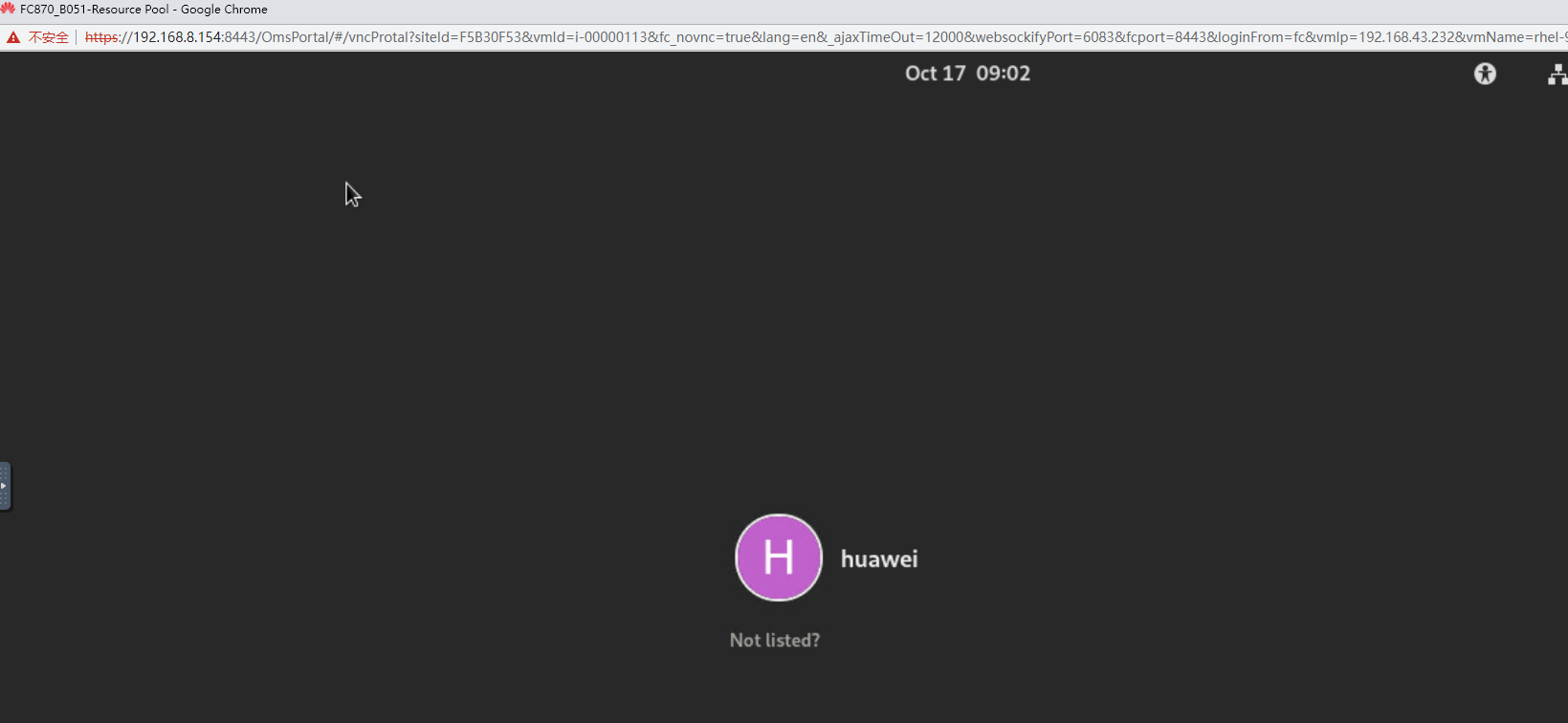 |
Conclusion |
|
Remarks |
3.8 Maintainability Function
3.8.1 Testing the Serial Port Log Record Function on the Host
Objective | Verify that serial port logs can be properly recorded on the host. |
Networking | Networking diagram for verifying functions |
Prerequisites | 1. FusionCompute is running properly. 2. A guest OS VM to be tested has been created and VMTools corresponding to the SIA has been installed on the VM. |
Procedure | 1. After logging in to the VM, add console=ttyS0,115200 to the /boot/grub/grub.cfg file. (Expected result 1) 2. Obtain the ID of the VM in step 1 and restart the VM. (Expected result 2) 3. Log in to the CNA host using SSH. In the /var/log/galaxenginelog/consolelog directory, query the log file named after the VM ID. (Expected result 3) |
Expected Result | 1. The configuration is successful. 2. The VM is restarted successfully. 3. The serial port log of the VM restart is recorded in the log file. |
Test Result | 1. After logging in to the VM, add console=ttyS0,115200 to the /boot/grub/grub.cfg file. (Expected result 1) 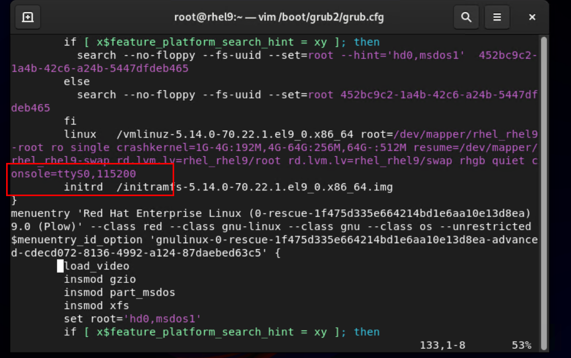 2. Obtain the ID of the VM in step 1 and restart the VM. (Expected result 2)  3. Log in to the CNA host using SSH. In the /var/log/galaxenginelog/consolelog directory, query the log file named after the VM ID. (Expected result 3) 
|
Conclusion |
|
Remarks |
3.9 Linux OS Customization
3.9.1 Customizing the Computer Name, Password, and NIC (Automatically Obtaining an IPv4 Address)
Objective | Verify that the computer name, password, and NIC (automatically obtaining an IPv4 address) can be customized. |
Networking | Networking diagram for verifying functions |
Prerequisites | 1. A guest OS VM to be tested has been created and VMTools corresponding to the SIA has been installed on the VM. 2. The VM has been converted to a template. Before converting the VM to a template, run the cat /etc/resolv.conf command to check whether the DNS address is automatically obtained. If so, delete the automatically-obtained address from the resolv.conf file. (If the DNS address is not deleted, the accuracy of the automatically-obtained DNS address will be affected during template deployment.) 3. An IPv4 DHCP server has been configured on the network where the VM resides. |
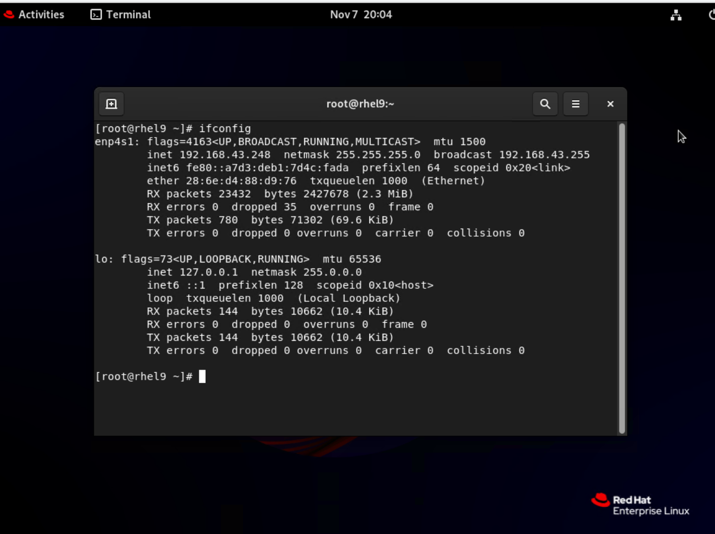
Procedure | 1. Choose Resource Pool > VM Templates. Right-click the VM template and choose Deploy VM Using Template from the shortcut menu. In the displayed box, configure parameters in Basic Information and Configure VM. Then, in the Customize OS step, select Customize using the Customization Wizard and set the computer name and administrator password in the Customize Attributes area. (Expected result 1) 2. Customize NIC settings, set IP Type to IPv4, IP Address Obtaining Mode to Automatically obtain IP address, and DNS Obtaining Mode to Automatically obtain DNS server address. (Expected result 2) 3. Log in to the VM using VNC and enter the existing administrator username as well as the customized password as an administrator to log in to the VM. (Expected result 3) 4. Run the hostname command to view the customized computer name. (Expected result 4) 5. View the customized NIC information in the Linux system: Run the ifconfig command to check the IPv4 address and mask of the VM. Run the route command to check the gateway. Run the cat /etc/resolv.conf command to check the DNS configuration. Ping the IPv4 address configured for the VM from the local host. (Expected result 5) 6. Restart the VM, view the customized information (configurations in steps 2 and 3), and ping the IPv4 address configured for the VM from the local host. (Expected result 6) |
Expected Result | 1. The customized attributes are correctly configured. 2. The customized NIC configuration is normal, and the VM is successfully deployed using the template. 3. You can use the customized password to log in to the OS. 4. The computer name is the customized name. 5. The customized NIC information is the same as the customized configuration, and the IPv4 address can be pinged locally. 6. The customized information is not lost, and the IPv4 address can be pinged locally. |
Test Result | 1. Choose Resource Pool > VM Templates. Right-click the VM template and choose Deploy VM Using Template from the shortcut menu. In the displayed box, configure parameters in Basic Information and Configure VM. Then, in the Customize OS step, select Customize using the Customization Wizard and set the computer name and administrator password in the Customize Attributes area. (Expected result 1) 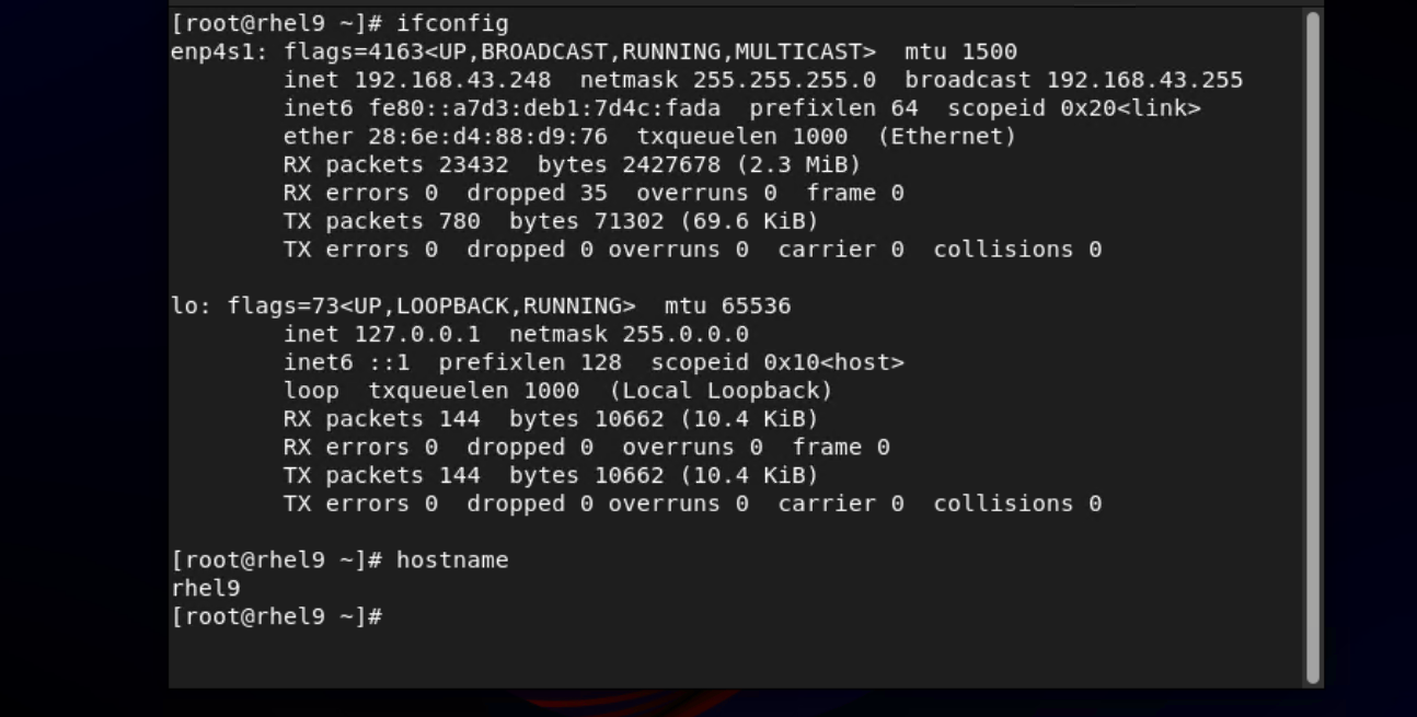 5. View the customized NIC information in the Linux system: Run the ifconfig command to check the IPv4 address and mask of the VM. Run the route command to check the gateway. Run the cat /etc/resolv.conf command to check the DNS configuration. Ping the IPv4 address configured for the VM from the local host. (Expected result 5) 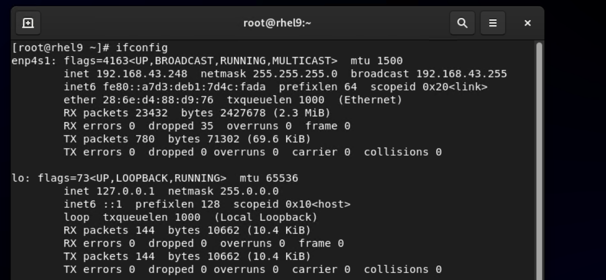  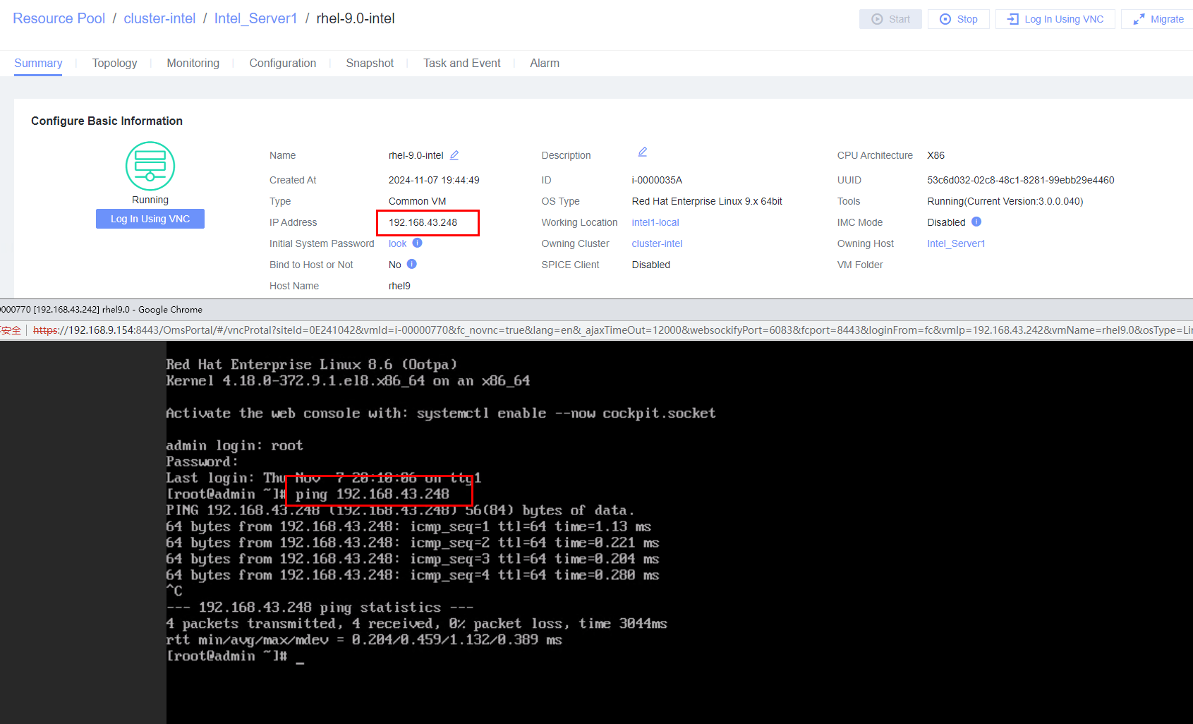 6. Restart the VM, view the customized information (configurations in steps 2 and 3), and ping the IPv4 address configured for the VM from the local host. (Expected result 6)  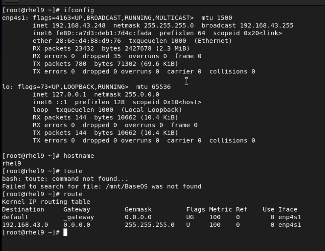 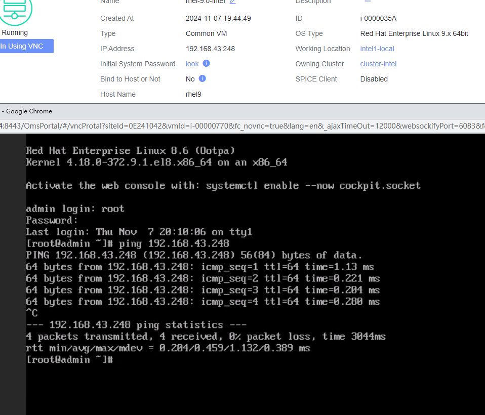 |
Conclusion |
|
Remarks |
3.9.2 Customizing the Computer Name, Password, and NIC (with the Specified IPv4 Address and Default Gateway)
Objective | Verify that the computer name, password, and NIC (with the specified IPv4 address and default gateway) can be customized. |
Networking | Networking diagram for verifying functions |
Prerequisites | 1. A guest OS VM to be tested has been created and VMTools corresponding to the SIA has been installed on the VM. 2. The VM has been converted to a template. Before converting the VM to a template, run the cat /etc/resolv.conf command to check whether the DNS address is automatically obtained. If so, delete the automatically-obtained address from the resolv.conf file. (If the DNS address is not deleted, the accuracy of the automatically-obtained DNS address during template deployment will be affected.) |
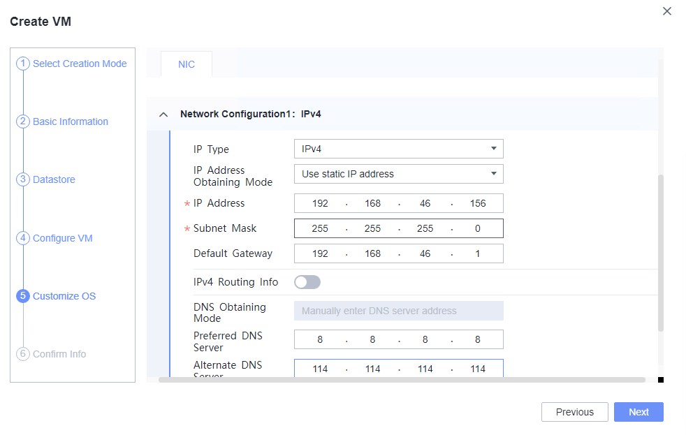
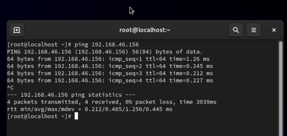
Procedure | 1. Choose Resource Pool > VM Templates. Right-click the VM template and choose Deploy VM Using Template from the shortcut menu. In the displayed box, configure parameters in Basic Information and Configure VM. Then, in the Customize OS step, select Customize using the Customization Wizard and set the computer name and administrator password in the Customize Attributes area. (Expected result 1) 2. Customize NIC settings, set IP type to IPv4, and configure the IP address, subnet mask, default gateway, primary DNS server address (for example, 8.8.8.8), and secondary DNS server address (for example, 114.114.114.114). (Expected result 2) 3. Log in to the VM using VNC and enter the existing administrator username as well as the customized password as an administrator to log in to the VM. (Expected result 3) 4. Run the hostname command to view the customized computer name. (Expected result 4) 5. View the customized NIC information in the Linux system: Run the ifconfig command to check the IPv4 address and mask of the VM. Run the route command to check the gateway. Run the cat /etc/resolv.conf command to check the DNS configuration. Ping the IPv4 address configured for the VM from the local host. (Expected result 5) 6. Restart the VM, view the customized information (configurations in steps 2 and 3), and ping the IPv4 address configured for the VM from the local host. (Expected result 6) |
Expected Result | 1. The customized attributes are correctly configured. 2. The customized NIC configuration is normal, and the VM is successfully deployed using the template. 3. You can use the customized password to log in to the OS. 4. The computer name is the customized name. 5. The customized NIC information is the same as the customized configuration, and the IPv4 address can be pinged locally. 6. The customized information is not lost, and the IPv4 address can be pinged locally. |
Test Result | 1. Choose Resource Pool > VM Templates. Right-click the VM template and choose Deploy VM Using Template from the shortcut menu. In the displayed box, configure parameters in Basic Information and Configure VM. Then, in the Customize OS step, select Customize using the Customization Wizard and set the computer name and administrator password in the Customize Attributes area. (Expected result 1) 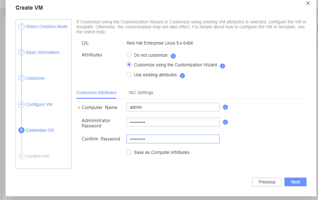
2. Customize NIC settings, set IP type to IPv4, and configure the IP address, subnet mask, default gateway, primary DNS server address (for example, 8.8.8.8), and secondary DNS server address (for example, 114.114.114.114). (Expected result 2)  3. Log in to the VM using VNC and enter the existing administrator username as well as the customized password as an administrator to log in to the VM. (Expected result 3) 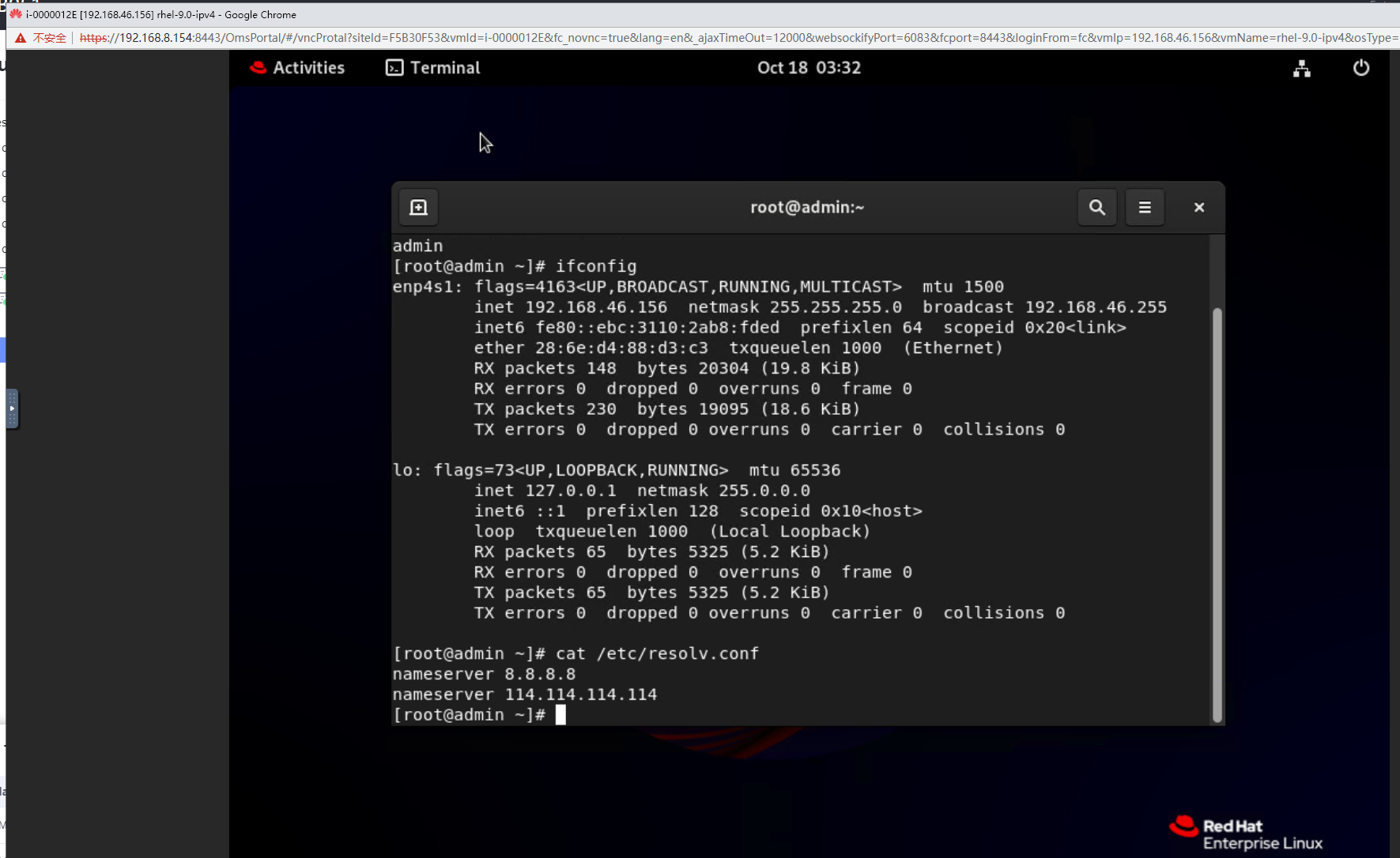 4. Run the hostname command to view the customized computer name. (Expected result 4) 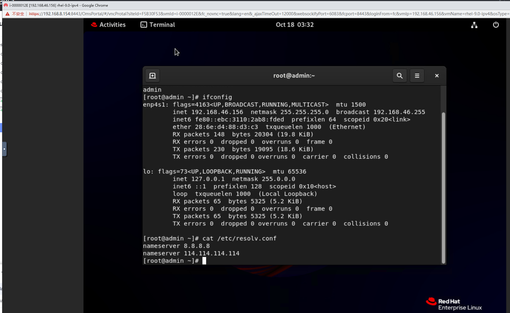 5. View the customized NIC information in the Linux system: Run the ifconfig command to check the IPv4 address and mask of the VM. Run the route command to check the gateway. Run the cat /etc/resolv.conf command to check the DNS configuration. Ping the IPv4 address configured for the VM from the local host. (Expected result 5) 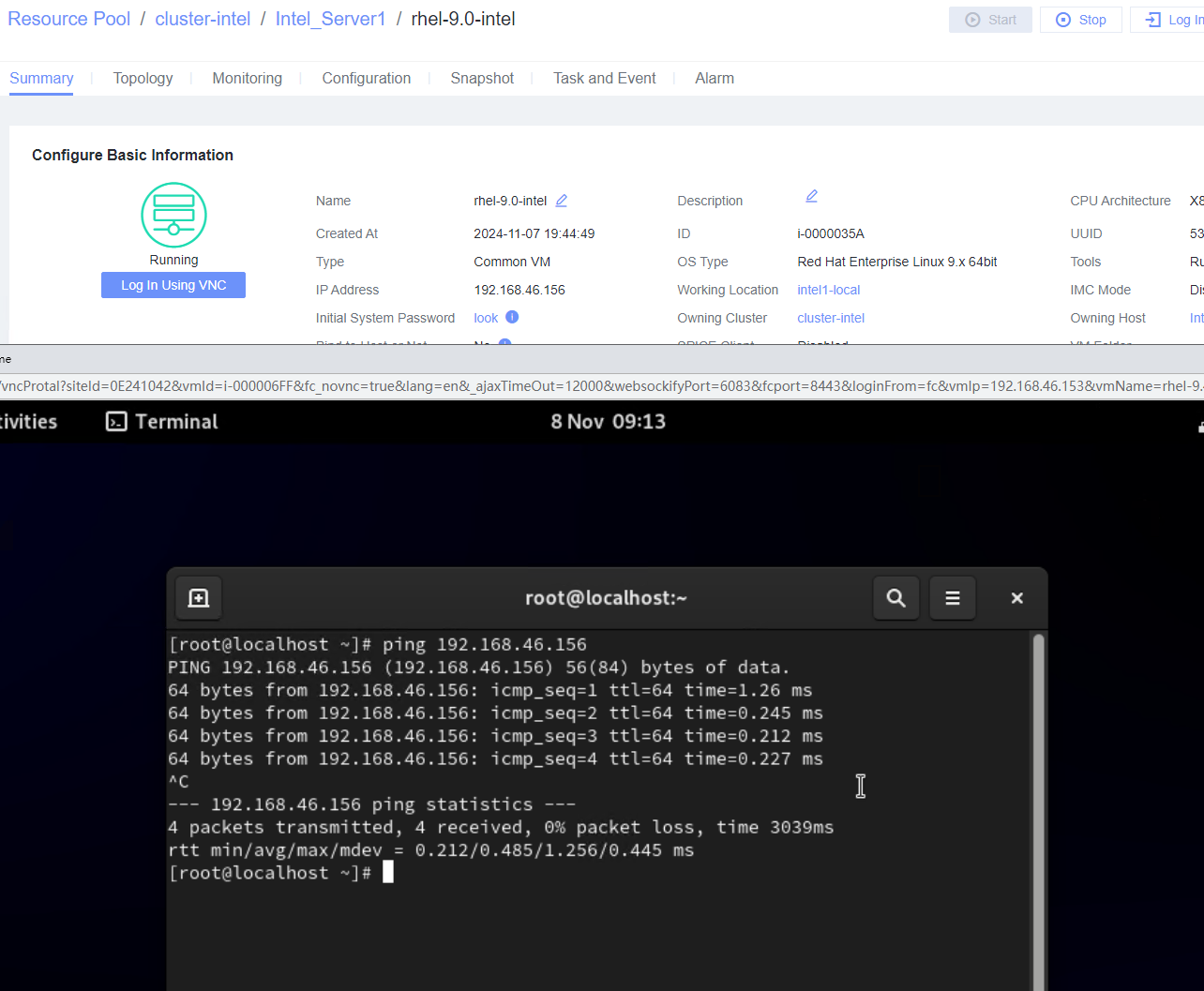 6. Restart the VM, view the customized information (configurations in steps 2 and 3), and ping the IPv4 address configured for the VM from the local host. (Expected result 6) 
|
Conclusion |
|
Remarks |
3.9.3Customizing the Computer Name, Password, and NIC (with Specified IPv4 Address and IPv4 Route Information)
Objective | Verify that the computer name, password, and NIC (with the specified IPv4 address and IPv4 route information) can be customized. |
Networking | Networking diagram for verifying functions |
Prerequisites | 1. A guest OS VM to be tested has been created and VMTools corresponding to the SIA has been installed on the VM. 2. The VM has been converted to a template. Before converting the VM to a template, run the cat /etc/resolv.conf command to check whether the DNS address is automatically obtained. If so, delete the automatically-obtained address from the resolv.conf file. (If the DNS address is not deleted, the accuracy of automatically-obtained DNS address during template deployment will be affected.) |
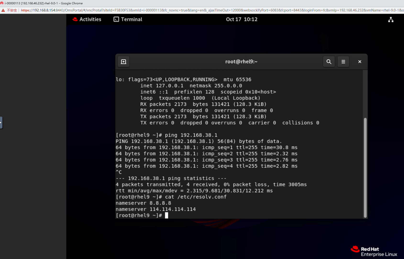
Procedure | 1. Choose Resource Pool > VM Templates. Right-click the VM template and choose Deploy VM Using Template from the shortcut menu. In the displayed box, configure parameters in Basic Information and Configure VM. Then, in the Customize OS step, select Customize using the Customization Wizard and set the computer name and administrator password in the Customize Attributes area. (Expected result 1) 2. Customize NIC settings, set IP type to IPv4, configure the IP address and subnet mask, enable IPv4 route information, and configure the IPv4 route gateway, IPv4 destination network, IPv4 destination network mask, primary DNS server address (for example, 8.8.8.8), and secondary DNS server address (for example, 114.114.114.114). (Expected result 2) 3. Log in to the VM using VNC and enter the existing administrator username as well as the customized password as an administrator to log in to the VM. (Expected result 3) 4. Run the hostname command to view the customized computer name. (Expected result 4) 5. View the customized NIC information in the Linux system: Run the ifconfig command to check the IPv4 address and mask of the VM. Run the route command to check the gateway. Run the cat /etc/resolv.conf command to check the DNS configuration. Ping the gateway address of the destination network from the VM. (Expected result 5) 6. Restart the VM and view the customized information (configurations in steps 2 and 3). Ping the gateway address of the destination network from the VM. (Expected result 6) |
Expected Result | 1. The customized attributes are correctly configured. 2. The customized NIC configuration is normal, and the VM is successfully deployed using the template. 3. You can use the customized password to log in to the OS. 4. The computer name is the customized name. 5. The customized NIC information is the same as the customized configuration. The VM can ping the gateway address of the destination network. 6. The customized information is not lost, and the VM can ping the gateway address of the destination network. |
Test Result | 1. Choose Resource Pool > VM Templates. Right-click the VM template and choose Deploy VM Using Template from the shortcut menu. In the displayed box, configure parameters in Basic Information and Configure VM. Then, in the Customize OS step, select Customize using the Customization Wizard and set the computer name and administrator password in the Customize Attributes area. (Expected result 1) 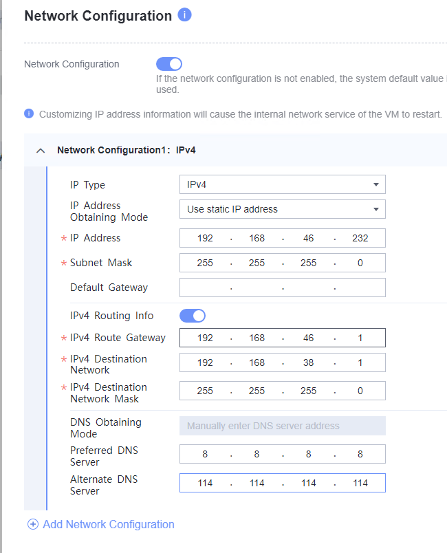 2. Customize NIC settings, set IP type to IPv4, configure the IP address and subnet mask, enable IPv4 route information, and configure the IPv4 route gateway, IPv4 destination network, IPv4 destination network mask, primary DNS server address (for example, 8.8.8.8), and secondary DNS server address (for example, 114.114.114.114). (Expected result 2) 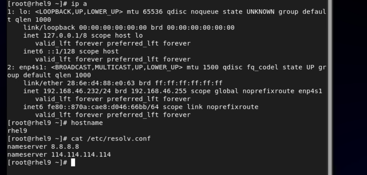 3. Log in to the VM using VNC and enter the existing administrator username as well as the customized password as an administrator to log in to the VM. (Expected result 3) 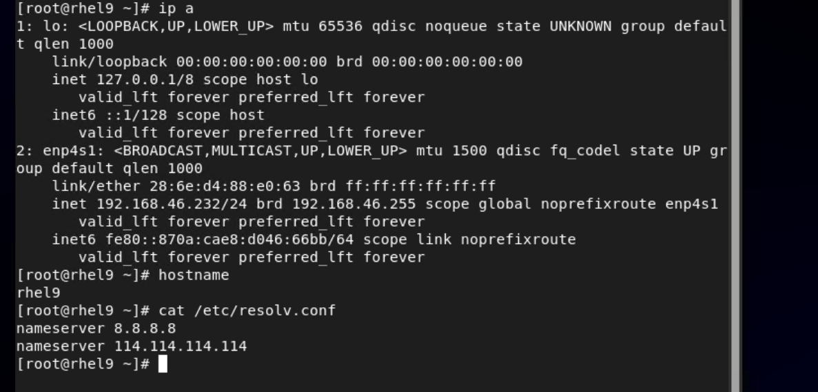 4. Run the hostname command to view the customized computer name. (Expected result 4) 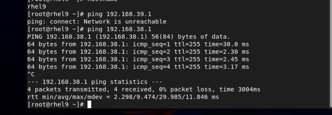 5. View the customized NIC information in the Linux system: Run the ifconfig command to check the IPv4 address and mask of the VM. Run the route command to check the gateway. Run the cat /etc/resolv.conf command to check the DNS configuration. Ping the gateway address of the destination network from the VM. (Expected result 5) 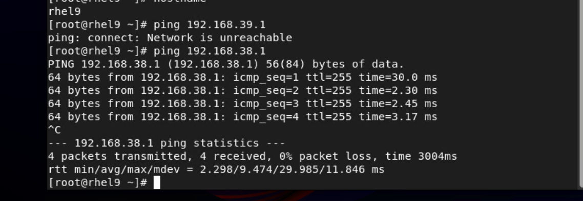 6. Restart the VM and view the customized information (configurations in steps 2 and 3). Ping the gateway address of the destination network from the VM. (Expected result 6) 
  |
Conclusion |
|
Remarks |
3.9.4 Customizing the Computer Name, Password, and NIC (Automatically Obtaining an IPv6 Address Through DHCP)
Objective | Verify that the computer name, password, and NIC (automatically obtaining an IPv6 address through DHCP) can be customized. |
Networking | Networking diagram for verifying functions |
Prerequisites |
|
Procedure | 1. Choose Resource Pool > VM Templates. Right-click the VM template and choose Deploy VM Using Template from the shortcut menu. In the displayed box, configure parameters in Basic Information and Configure VM. Then, in the Customize OS step, select Customize using the Customization Wizard and set the computer name and administrator password in the Customize Attributes area. (Expected result 1) 2. Customize NIC settings, set IP Type to IPv6, IP Address Obtaining Mode to Use DHCP service to automatically obtain IPv6 address, and DNS Obtaining Mode to Automatically obtain DNS server address. (Expected result 2) 3. Log in to the VM using VNC and enter the existing administrator username as well as the customized password as an administrator to log in to the VM. (Expected result 3) 4. Run the hostname command to view the customized computer name. (Expected result 4) 5. View the customized NIC information in the Linux system: Run the ifconfig command to check the IPv6 address and mask of the VM. Run the route -6 command to check the gateway. Run the cat /etc/resolv.conf command to check the DNS configuration. Ping the IPv6 address configured for the VM from the local host. (Expected result 5) 6. Restart the VM, view the customized information (configurations in steps 2 and 3), and ping the IPv6 address configured for the VM from the local host. (Expected result 6) |
Expected Result | 1. The customized attributes are correctly configured. 2. The customized NIC configuration is normal, and the VM is successfully deployed using the template. 3. You can use the customized password to log in to the OS. 4. The computer name is the customized name. 5. The customized NIC information is the same as the customized configuration, and the IPv6 address can be pinged locally. 6. The customized information is not lost, and the IPv6 address can be pinged locally. |
Test Result | 1. Choose Resource Pool > VM Templates. Right-click the VM template and choose Deploy VM Using Template from the shortcut menu. In the displayed box, configure parameters in Basic Information and Configure VM. Then, in the Customize OS step, select Customize using the Customization Wizard and set the computer name and administrator password in the Customize Attributes area. (Expected result 1) 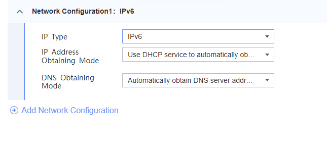 2. Customize NIC settings, set IP Type to IPv6, IP Address Obtaining Mode to Use DHCP service to automatically obtain IPv6 address, and DNS Obtaining Mode to Automatically obtain DNS server address. (Expected result 2)  3. Log in to the VM using VNC and enter the existing administrator username as well as the customized password as an administrator to log in to the VM. (Expected result 3)  4. Run the hostname command to view the customized computer name. (Expected result 4) 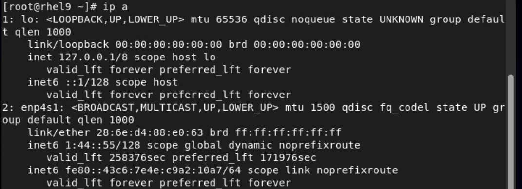 5. View the customized NIC information in the Linux system: Run the ifconfig command to check the IPv6 address and mask of the VM. Run the route -6 command to check the gateway. Run the cat /etc/resolv.conf command to check the DNS configuration. Ping the IPv6 address configured for the VM from the local host. (Expected result 5) 
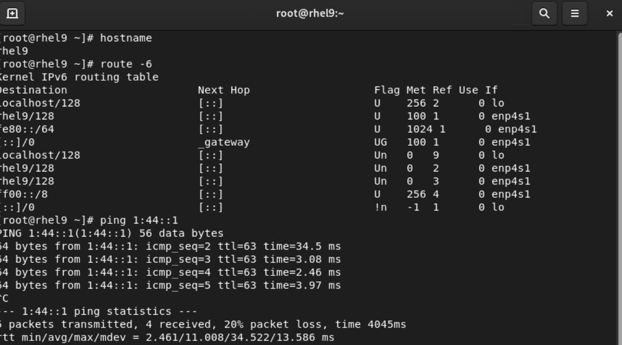
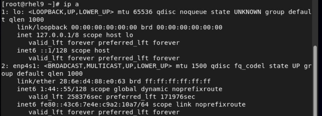 6. Restart the VM, view the customized information (configurations in steps 2 and 3), and ping the IPv6 address configured for the VM from the local host. (Expected result 6) 
 |
Conclusion |
|
Remarks |
3.9.5 Customizing the Computer Name, Password, and NIC (Automatically Obtaining an IPv6 Address by Router Advertisement)
Objective | Verify that the computer name, password, and NIC (automatically obtaining an IPv6 address by router advertisement) can be customized. |
Networking | Networking diagram for verifying functions |
Prerequisites | 1. A guest OS VM to be tested has been created and VMTools corresponding to the SIA has been installed on the VM. 2. The VM has been converted to a template. Before converting the VM to a template, run the cat /etc/resolv.conf command to check whether the DNS address is automatically obtained. If so, delete the automatically-obtained address from the resolv.conf file. (If the DNS address is not deleted, the accuracy of the automatically-obtained DNS address will be affected during template deployment.) 3. The IPv6 route advertisement service has been configured on the network where the VM resides. |
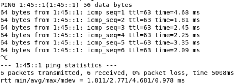
Procedure | 1. Choose Resource Pool > VM Templates. Right-click the VM template and choose Deploy VM Using Template from the shortcut menu. In the displayed box, configure parameters in Basic Information and Configure VM. Then, in the Customize OS step, select Customize using the Customization Wizard and set the computer name and administrator password in the Customize Attributes area. (Expected result 1) 2. Customize NIC settings, set IP Type to IPv6, IP Address Obtaining Mode to Use router advertisement function to automatically obtain IPv6 address, and DNS Obtaining Mode to Automatically obtain DNS server address. (Expected result 2) 3. Log in to the VM using VNC and enter the existing administrator username as well as the customized password as an administrator to log in to the VM. (Expected result 3) 4. Run the hostname command to view the customized computer name. (Expected result 4) 5. View the customized NIC information in the Linux system: Run the ifconfig command to check the IPv6 address and mask of the VM. Run the route -6 command to check the gateway. Run the cat /etc/resolv.conf command to check the DNS configuration. Ping the IPv6 address configured for the VM from the local host. (Expected result 5) 6. Restart the VM, view the customized information (configurations in steps 2 and 3), and ping the IPv6 address configured for the VM from the local host. (Expected result 6) |
Expected Result | 1. The customized attributes are correctly configured. 2. The customized NIC configuration is normal, and the VM is successfully deployed using the template. 3. You can use the customized password to log in to the OS. 4. The computer name is the customized name. 5. The customized NIC information is the same as the customized configuration. The IPv6 address obtained through route advertisement is of the global type. The VM can ping the gateway address of the destination network. 6. The customized information is not lost, and the VM can ping the gateway address of the destination network. |
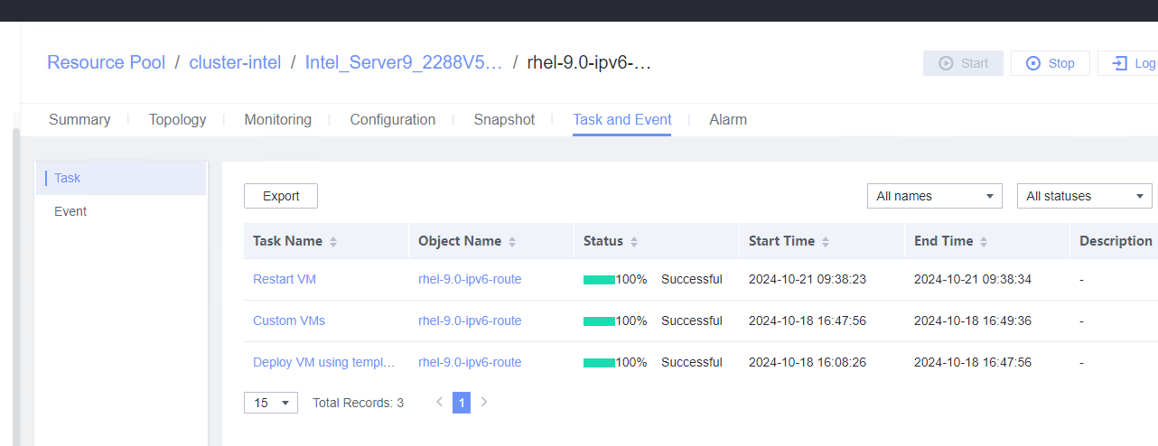
Test Result | 1. Choose Resource Pool > VM Templates. Right-click the VM template and choose Deploy VM Using Template from the shortcut menu. In the displayed box, configure parameters in Basic Information and Configure VM. Then, in the Customize OS step, select Customize using the Customization Wizard and set the computer name and administrator password in the Customize Attributes area. (Expected result 1) 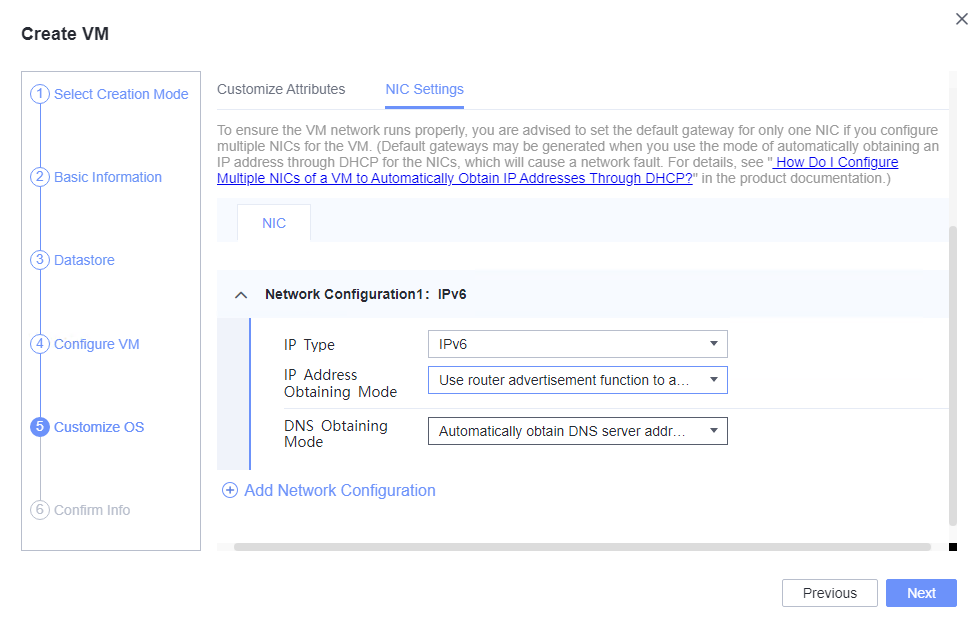 2. Customize NIC settings, set IP Type to IPv6, IP Address Obtaining Mode to Use router advertisement function to automatically obtain IPv6 address, and DNS Obtaining Mode to Automatically obtain DNS server address. (Expected result 2) 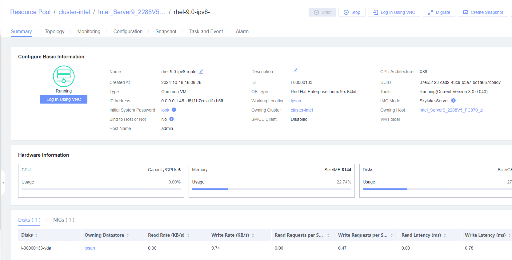 3. Log in to the VM using VNC and enter the existing administrator username as well as the customized password as an administrator to log in to the VM. (Expected result 3)  4. Run the hostname command to view the customized computer name. (Expected result 4) 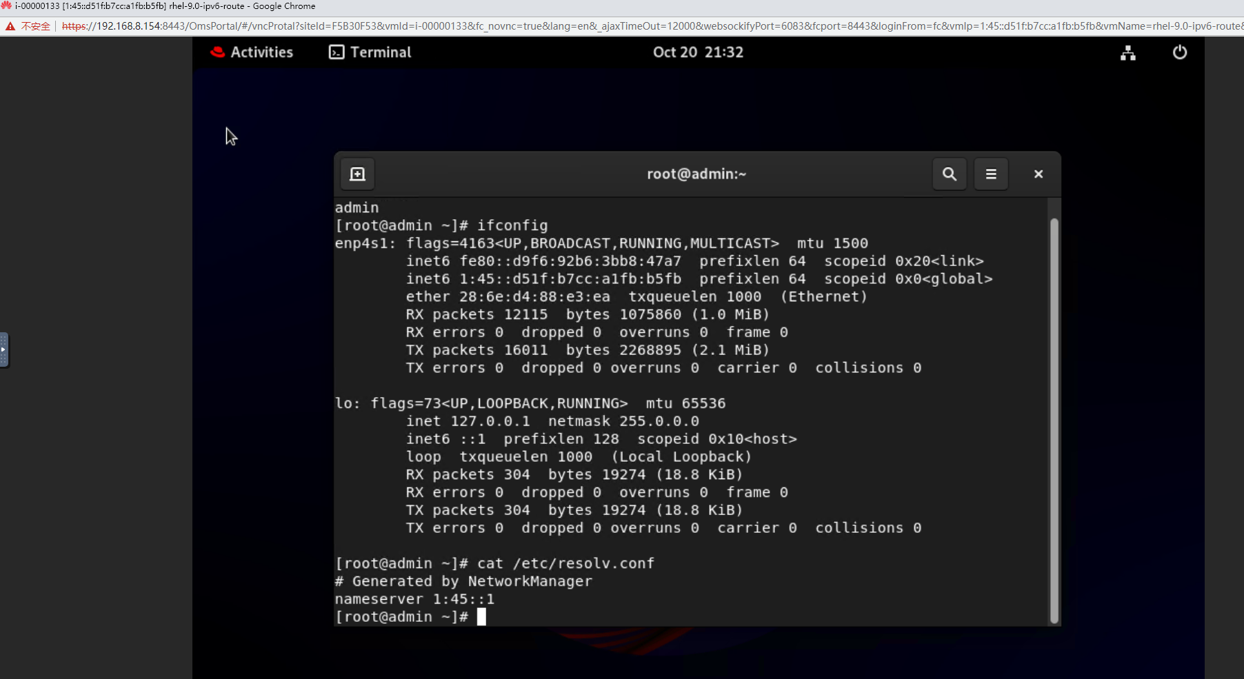 5. View the customized NIC information in the Linux system: Run the ifconfig command to check the IPv6 address and mask of the VM. Run the route -6 command to check the gateway. Run the cat /etc/resolv.conf command to check the DNS configuration. Ping the IPv6 address configured for the VM from the local host. (Expected result 5) 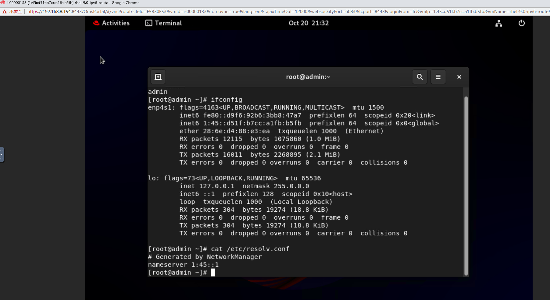 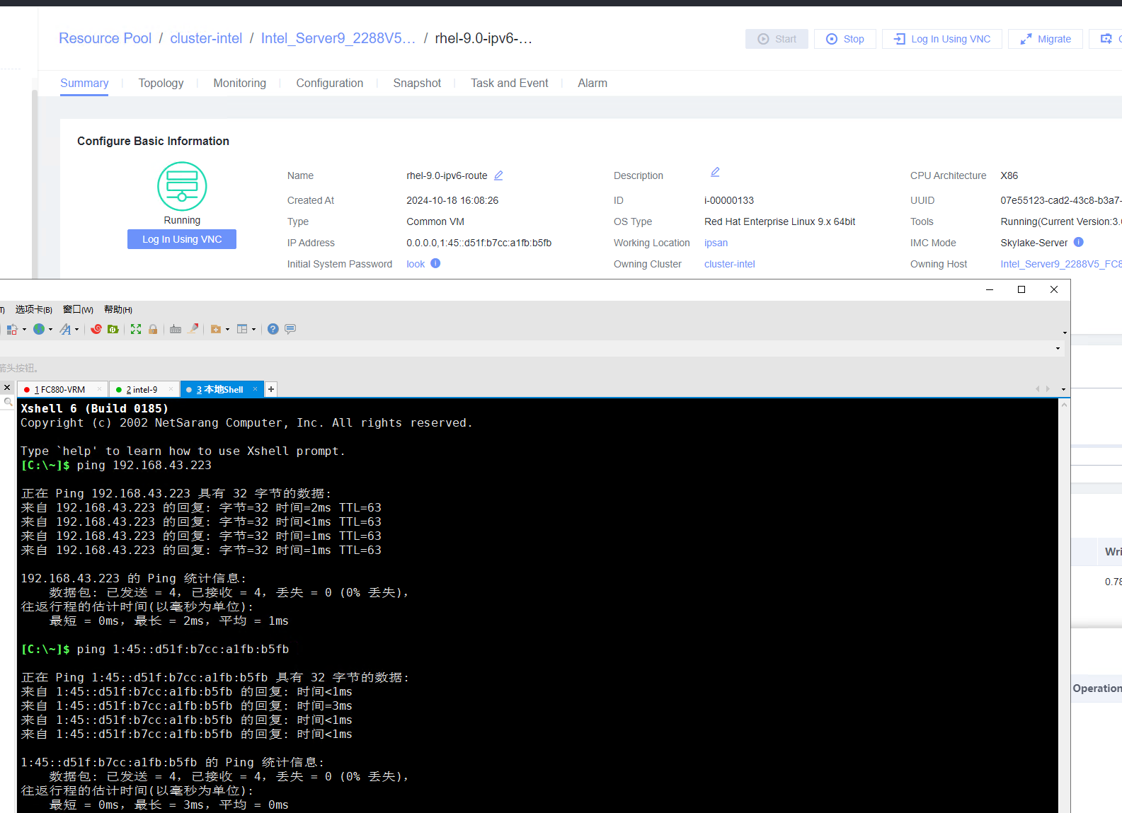

 |
Conclusion |
|
Remarks |
3.9.6 Customizing the Computer Name, Password, and NIC (with Specified IPv6 Address)
Objective | Verify that the computer name, password, and NIC (with the specified IPv6 address) can be customized. |
Networking | Networking diagram for verifying functions |
Prerequisites | 1. A guest OS VM to be tested has been created and VMTools corresponding to the SIA has been installed on the VM. 2. The VM has been converted to a template. Before converting the VM to a template, run the cat /etc/resolv.conf command to check whether the DNS address is automatically obtained. If so, delete the automatically-obtained address from the resolv.conf file. (If the DNS address is not deleted, the accuracy of the automatically-obtained DNS address during template deployment will be affected.) |
Procedure | 1. Choose Resource Pool > VM Templates. Right-click the VM template and choose Deploy VM Using Template from the shortcut menu. In the displayed box, configure parameters in Basic Information and Configure VM. Then, in the Customize OS step, select Customize using the Customization Wizard and set the computer name and administrator password in the Customize Attributes area. (Expected result 1) 2. Customize NIC settings, set IP Type to IPv6 and IP Address Obtaining Mode to Use static IPv6 address, and enter the IP address and subnet prefix length. Enable IPv6 route information, configure the IPv6 route gateway, IPv6 destination network, and IPv6 destination network prefix length, and set the primary and secondary DNS server addresses. (Expected result 2) 3. Log in to the VM using VNC and enter the existing administrator username as well as the customized password as an administrator to log in to the VM. (Expected result 3) 4. Run the hostname command to view the customized computer name. (Expected result 4) 5. View the customized NIC information in the Linux system: Run the ifconfig command to check the IPv6 address and mask of the VM. Run the route -6 command to check the gateway. Run the cat /etc/resolv.conf command to check the DNS configuration. Ping the gateway address of the destination network from the VM. (Expected result 5) 6. Restart the VM and view the customized information (configurations in steps 2 and 3). Ping the gateway address of the destination network from the VM. (Expected result 6) |
Expected Result | 1. The customized attributes are correctly configured. 2. The customized NIC configuration is normal, and the VM is successfully deployed using the template. 3. You can use the customized password to log in to the OS. 4. The computer name is the customized name. 5. The customized NIC information is the same as the customized configuration. The VM can ping the gateway address of the destination network. 6. The customized information is not lost, and the VM can ping the gateway address of the destination network. |
Test Result | 1. Choose Resource Pool > VM Templates. Right-click the VM template and choose Deploy VM Using Template from the shortcut menu. In the displayed box, configure parameters in Basic Information and Configure VM. Then, in the Customize OS step, select Customize using the Customization Wizard and set the computer name and administrator password in the Customize Attributes area. (Expected result 1) 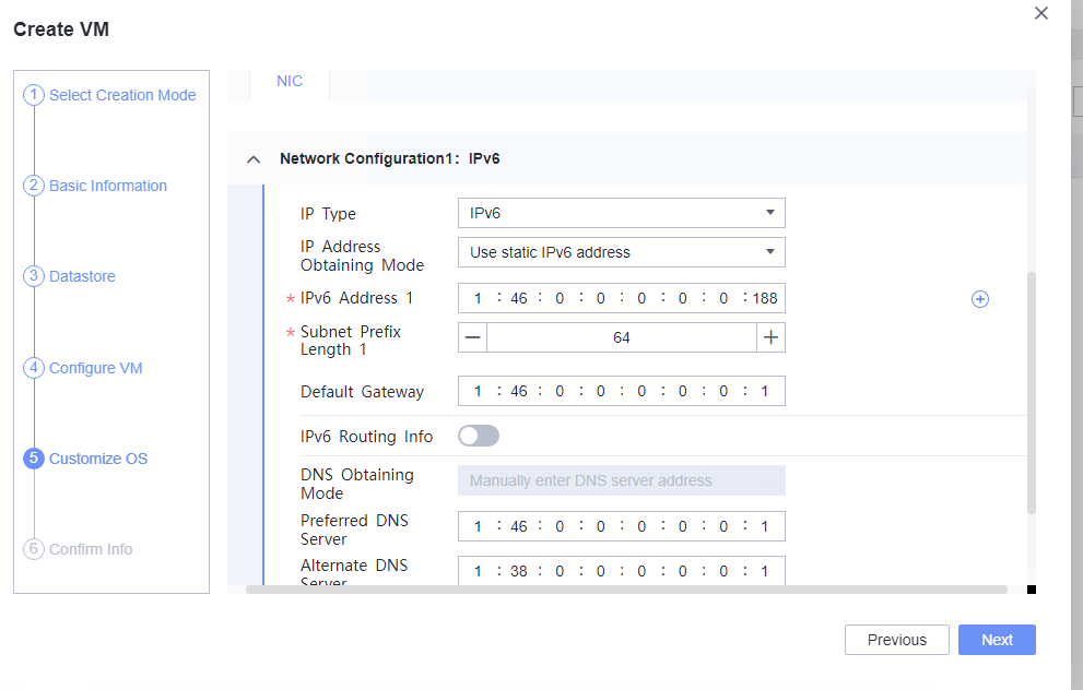 2. Customize NIC settings, set IP Type to IPv6 and IP Address Obtaining Mode to Use static IPv6 address, and enter the IP address and subnet prefix length. Enable IPv6 route information, configure the IPv6 route gateway, IPv6 destination network, and IPv6 destination network prefix length, and set the primary and secondary DNS server addresses. (Expected result 2) 
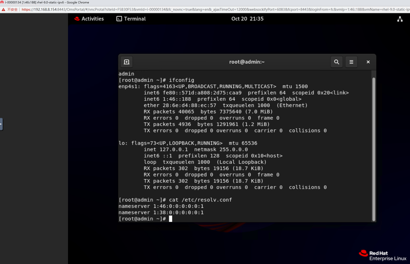
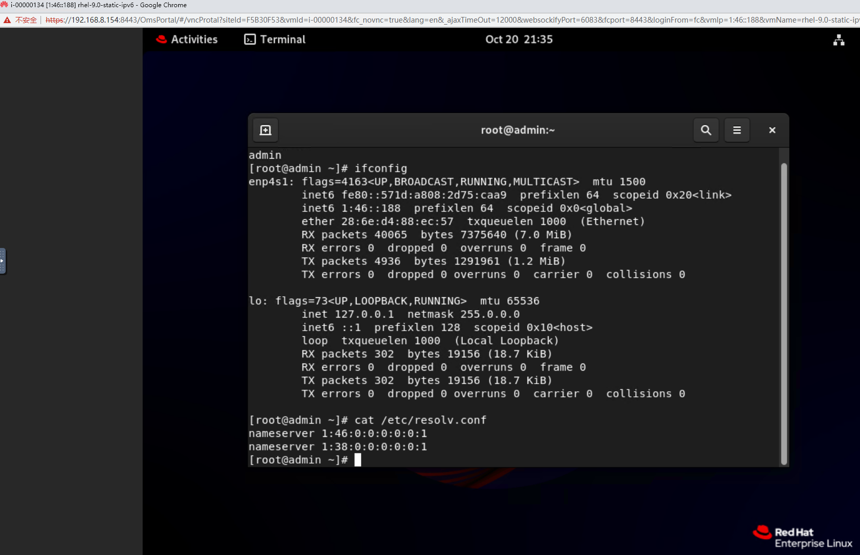 4. Run the hostname command to view the customized computer name. (Expected result 4) 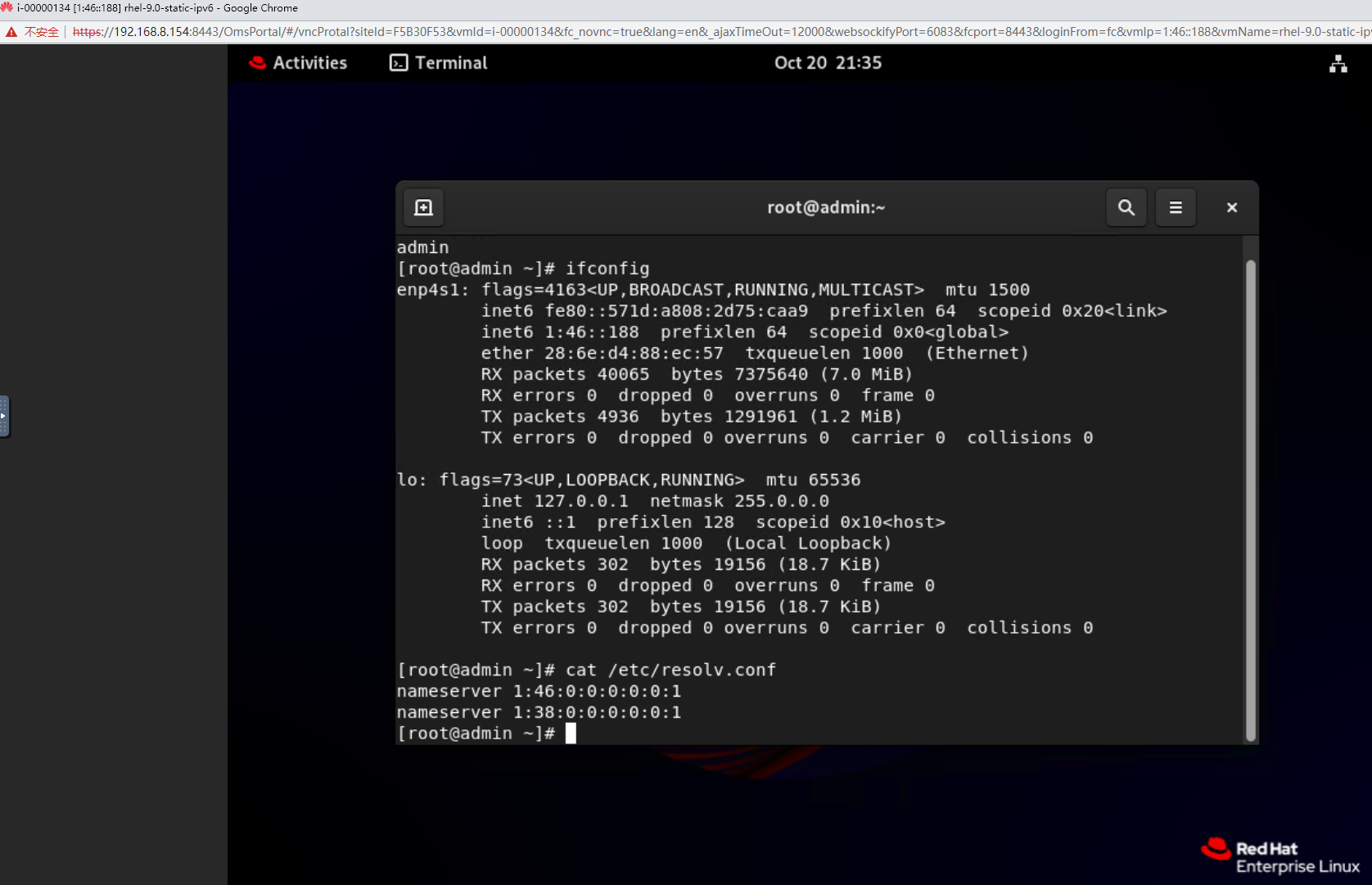 5. View the customized NIC information in the Linux system: Run the ifconfig command to check the IPv6 address and mask of the VM. Run the route -6 command to check the gateway. Run the cat /etc/resolv.conf command to check the DNS configuration. Ping the gateway address of the destination network from the VM. (Expected result 5) 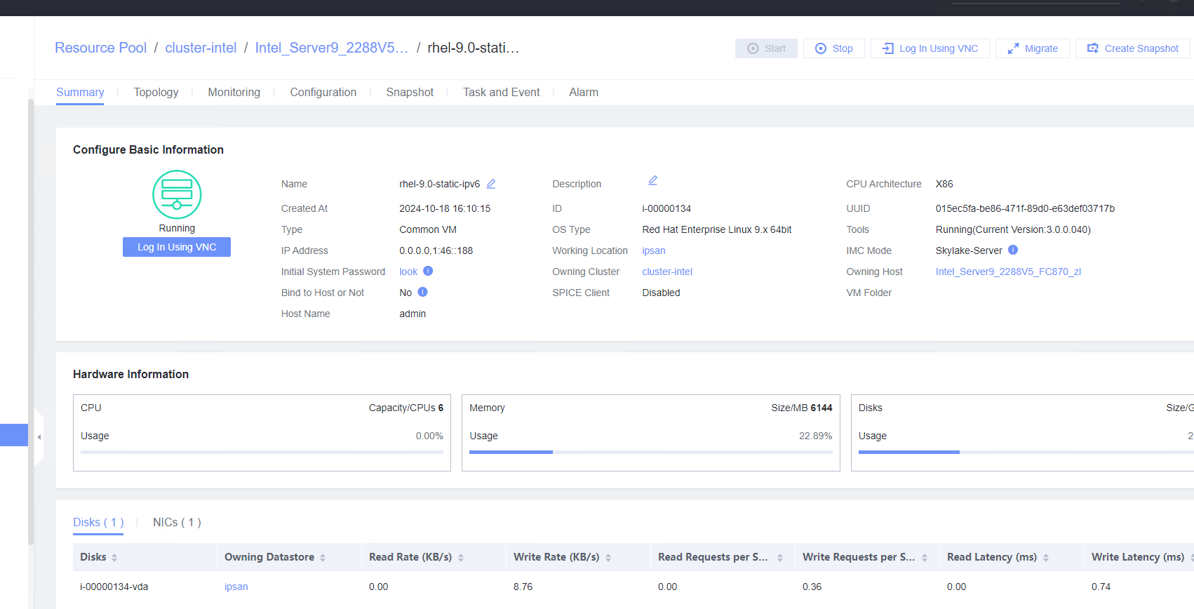
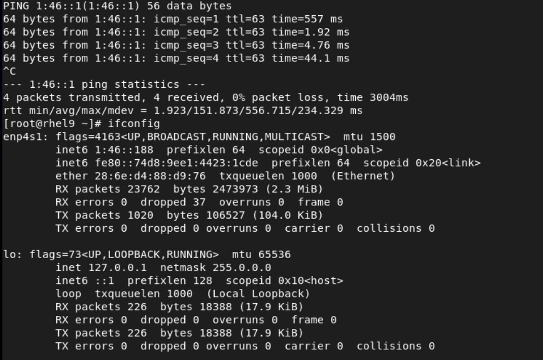
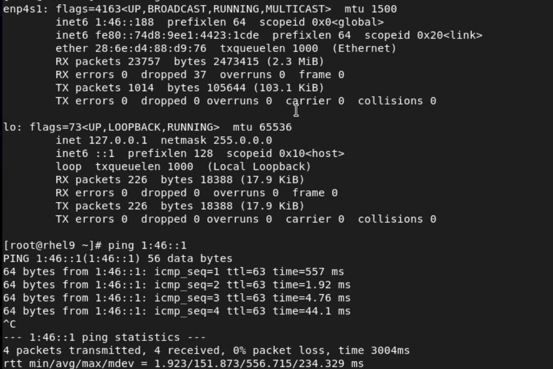 6. Restart the VM and view the customized information (configurations in steps 2 and 3). Ping the gateway address of the destination network from the VM. (Expected result 6) 
 |
Conclusion |
|
Remarks |
3.10 Snapshot
3.10.1 Creating a Storage Snapshot
Objective | Verify that a storage snapshot can be successfully created for a VM. |
Networking | Networking diagram for verifying functions |
Prerequisites | 1. FusionCompute is running properly. 2. A local image file or template is available for deploying and creating a VM or importing a VM template. 3. VMTools has been installed on a VM to be tested. |
Procedure | 1. Create a VM running the guest OS to be tested. For details, see Operation and Maintenance > Service Management > Provisioning a VM > Creating a Bare VM in the FusionCompute 8.X.X Product Documentation. (Expected result 1) 2. Right-click the VM to be tested and choose Create Snapshot from the shortcut menu to create a common snapshot (deselect Memory snapshot and Consistency snapshot). (Expected result 2) 3. Create a file on the VM, select the VM and click the Snapshot tab, select the snapshot created in step 2, and restore the VM using the snapshot. (Expected result 3) |
Expected Result | 1. The VM is created successfully. 2. The common snapshot is successfully created for the VM. 3. The VM is successfully restored using the snapshot, but the created file is lost. |
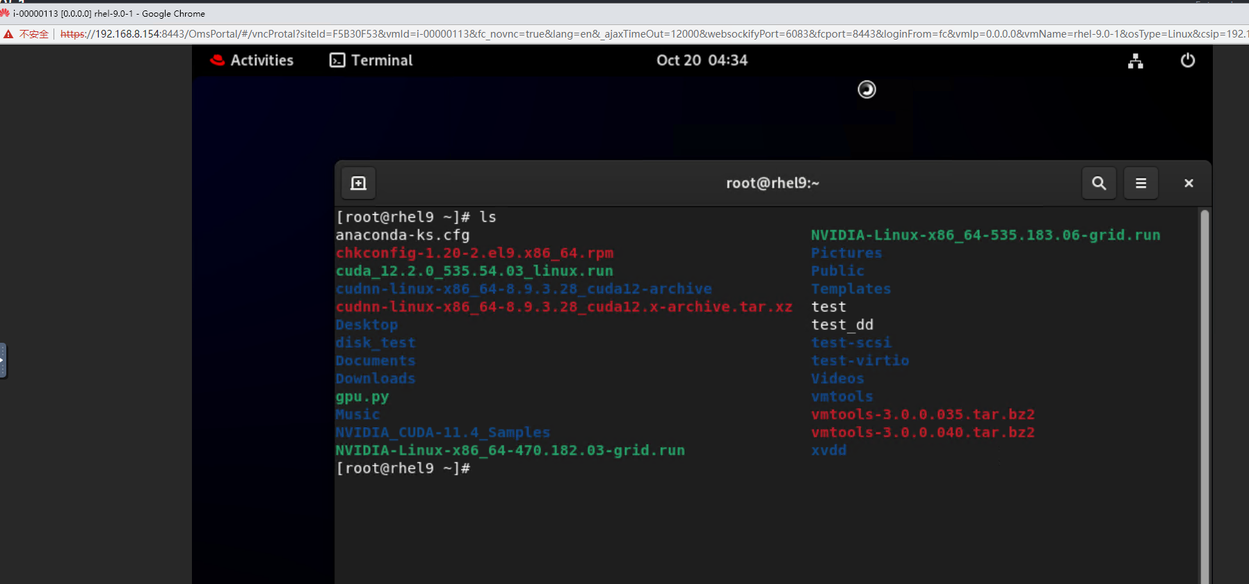
Test Result | 1. Create a VM running the guest OS to be tested. For details, see Operation and Maintenance > Service Management > Provisioning a VM > Creating a Bare VM in the FusionCompute 8.X.X Product Documentation. (Expected result 1) 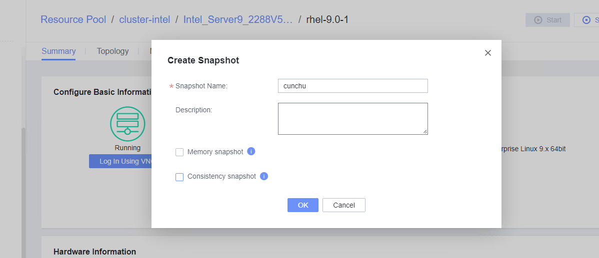 2. Right-click the VM to be tested and choose Create Snapshot from the shortcut menu to create a common snapshot (deselect Memory snapshot and Consistency snapshot). (Expected result 2) 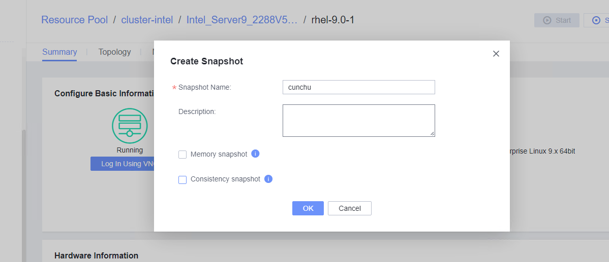
 3. Create a file on the VM, select the VM and click the Snapshot tab, select the snapshot created in step 2, and restore the VM using the snapshot. (Expected result 3) 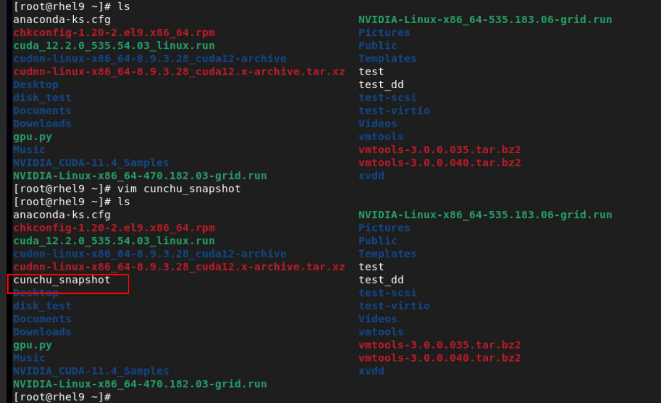 restore the VM: 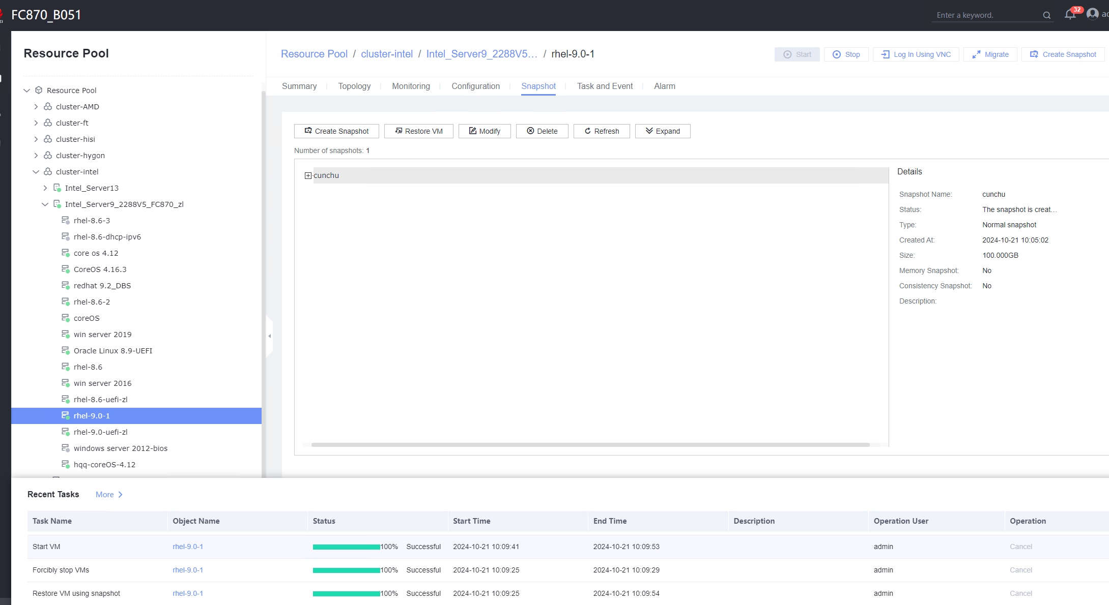
 |
Conclusion |
|
Remarks |
3.10.2 Creating a Memory Snapshot
Objective | Verify that a memory snapshot can be successfully created for a VM. |
Networking | Networking diagram for verifying functions |
Prerequisites | 1. FusionCompute is running properly. 2. A local image file or template is available for deploying and creating a VM or importing a VM template. 3. VMTools has been installed on a VM to be tested. 4. In FusionCompute 8.5.0 and later versions, Linux VMs of the Arm architecture support memory snapshots. |
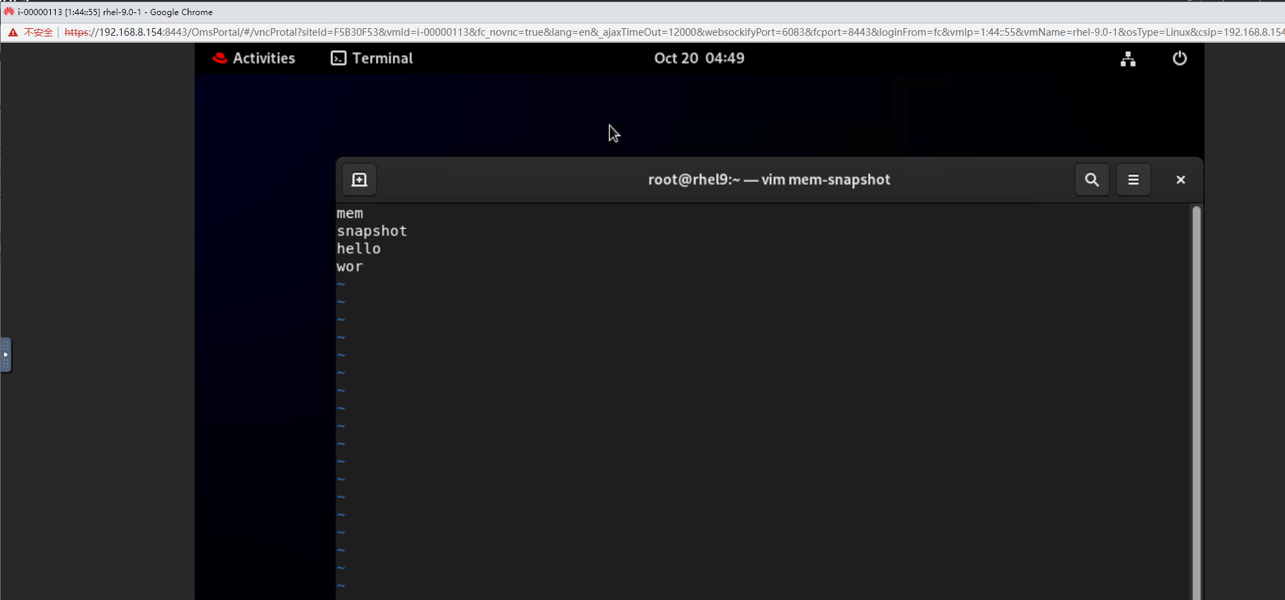
Procedure | 1. Create a VM running the guest OS to be tested. For details, see Operation and Maintenance > Service Management > Provisioning a VM > Creating a Bare VM in the FusionCompute 8.X.X Product Documentation. (Expected result 1) 2. Create a file on the VM and open the file. (Expected result 2) 3. Right-click the VM to be tested and choose Create Snapshot from the shortcut menu to create a memory snapshot (select Memory snapshot but deselect Consistency snapshot). (Expected result 3) 4. Close the file in step 2, select the VM and click the Snapshot tab, select the snapshot created in step 3, and restore the VM using the snapshot. (Expected result 4) |
Expected Result | 1. The VM is created successfully. 2. The file is opened. 3. A memory snapshot is successfully created for the VM. 4. The VM is successfully restored using the snapshot, and the file in step 2 is still open. |
Test Result | 1. Create a VM running the guest OS to be tested. For details, see Operation and Maintenance > Service Management > Provisioning a VM > Creating a Bare VM in the FusionCompute 8.X.X Product Documentation. (Expected result 1) 2. Create a file on the VM and open the file. (Expected result 2) 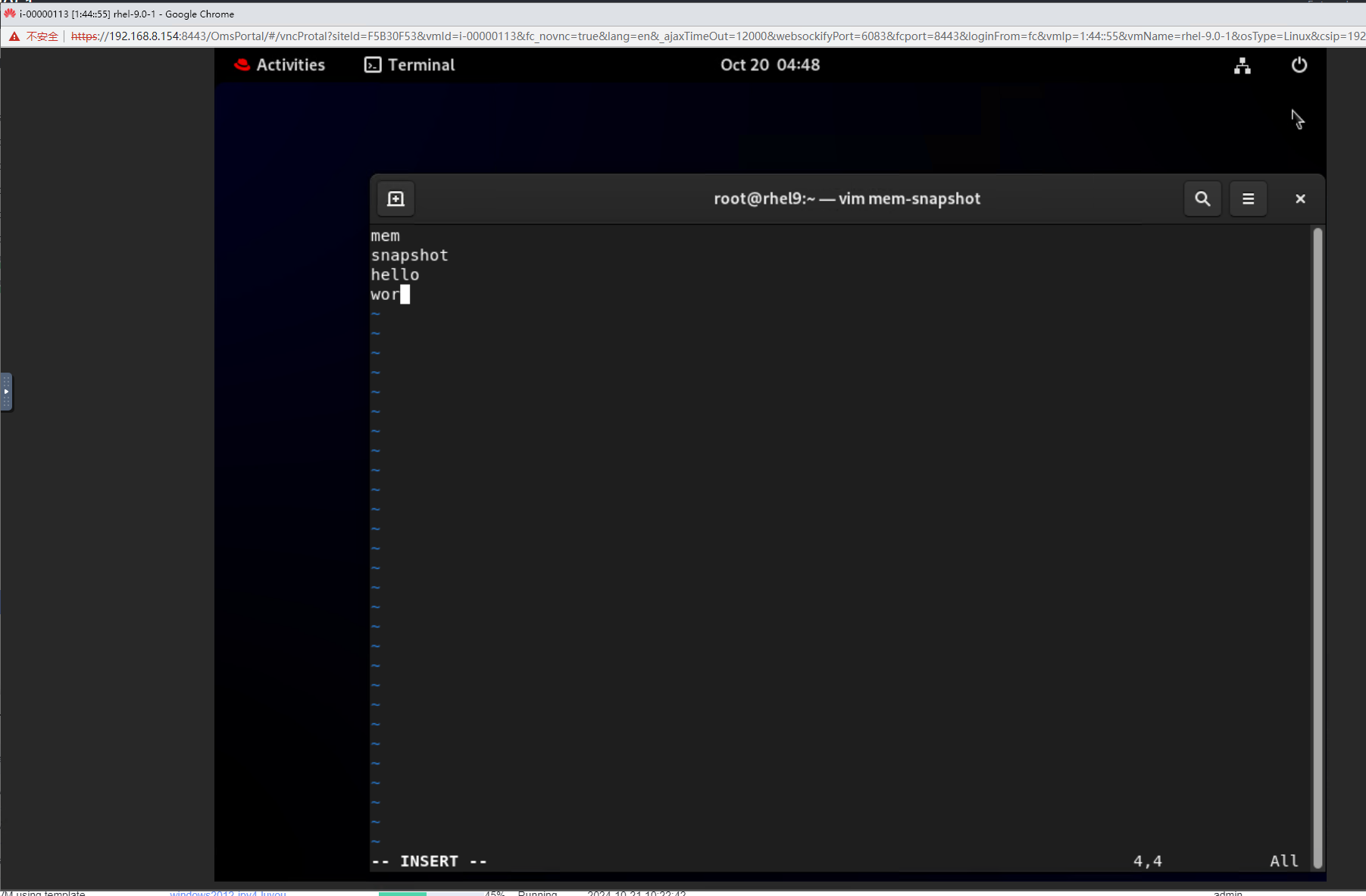 3. Right-click the VM to be tested and choose Create Snapshot from the shortcut menu to create a memory snapshot (select Memory snapshot but deselect Consistency snapshot). (Expected result 3) 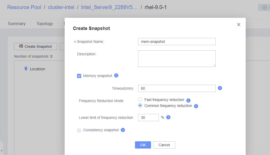 4. Close the file in step 2, select the VM and click the Snapshot tab, select the snapshot created in step 3, and restore the VM using the snapshot. (Expected result 4)
  |
Conclusion |
|
Remarks |
3.10.3 Creating a Consistency Snapshot
Objective | Verify that a consistency snapshot can be successfully created for a VM. |
Networking | Networking diagram for verifying functions |
Prerequisites | 1. FusionCompute is running properly. 2. A local image file or template is available for deploying and creating a VM or importing a VM template. 3. VMTools has been installed on a VM to be tested. 4. In FusionCompute 8.5.0 and later versions, Linux VMs of the x86 and Arm architecture support consistency snapshots. |
Procedure | 1. Log in to the VRM, provision a VM, and obtain the VM ID, for example, i-00000036. Log in to the CNA host and run the virsh qemu-agent-command i-00000036 –cmd ‘{« execute »: »guest-fsfreeze-freeze »}’ command to freeze the file system of the VM. 2. Log in to the VM background and perform a write operation, for example, run the touch test command. 3. Run the virsh qemu-agent-command i-00000036 –cmd ‘{« execute »: »guest-fsfreeze-status »}’ command to query the status on the CNA host background. The status is frozen. 4. Run the virsh qemu-agent-command i-00000036 –cmd ‘{« execute »: »guest-fsfreeze-thaw »}’ command to unfreeze the VM on the host. 5. Run the virsh qemu-agent-command i-00000036 –cmd ‘{« execute »: »guest-fsfreeze-status »}’ command to check the status on the host. 6. Log in to the VM and perform a write operation. 7. Right-click the tested VM and choose Create Snapshot from the shortcut menu to create a common snapshot (deselect Memory snapshot but select Consistency snapshot). 8. Create a file on the VM, select the VM and click the Snapshot tab, and restore the VM using the snapshot. |
Expected Result | 1. If the {« return »:3} is displayed, the VM is frozen successfully. 2. If the command execution is suspended, the VM has been frozen. 3. Return value: {« return »: « frozen »} 4. Return value: {« return »:3} 5. Return value: {« return »: thawed »} 6. The write operation is not suspended. 7. The write operation is suspended during snapshot creation. After the snapshot is successfully created, the write operation is normal. 8. The VM is successfully restored using the snapshot. |
Test Result | 1. Log in to the VRM, provision a VM, and obtain the VM ID, for example, i-00000036. Log in to the CNA host and run the virsh qemu-agent-command i-00000036 –cmd ‘{« execute »: »guest-fsfreeze-freeze »}’ command to freeze the file system of the VM.  5. Run the virsh qemu-agent-command i-00000036 –cmd ‘{« execute »: »guest-fsfreeze-status »}’ command to check the status on the host.  6. Log in to the VM and perform a write operation. 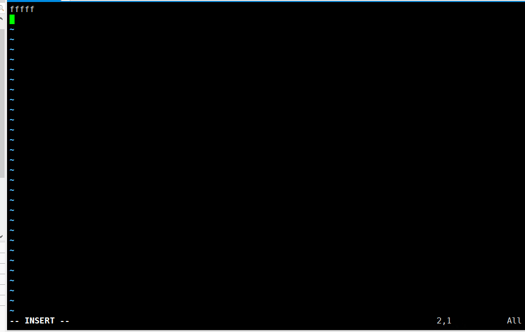 7. Right-click the tested VM and choose Create Snapshot from the shortcut menu to create a common snapshot (deselect Memory snapshot but select Consistency snapshot). 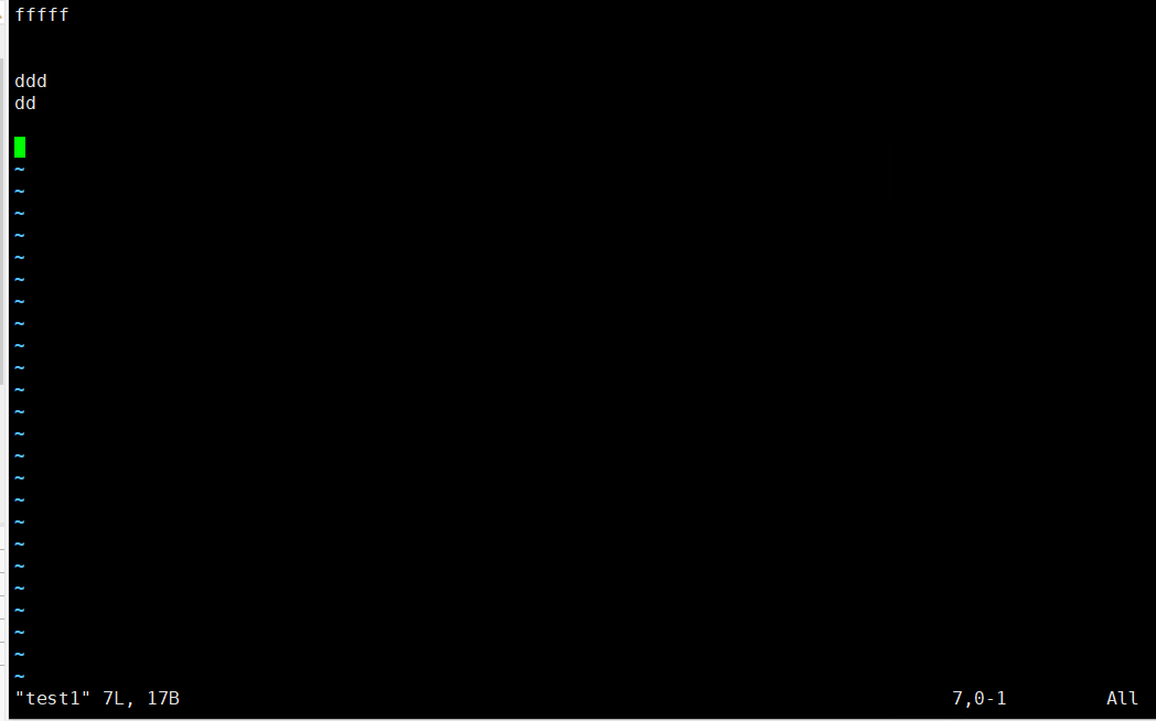 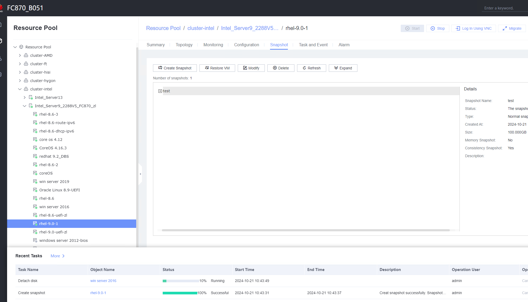 8. Create a file on the VM, select the VM and click the Snapshot tab, and restore the VM using the snapshot. restore the VM:  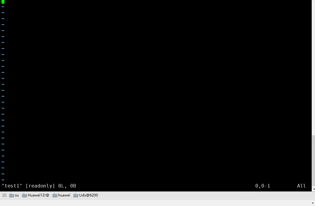 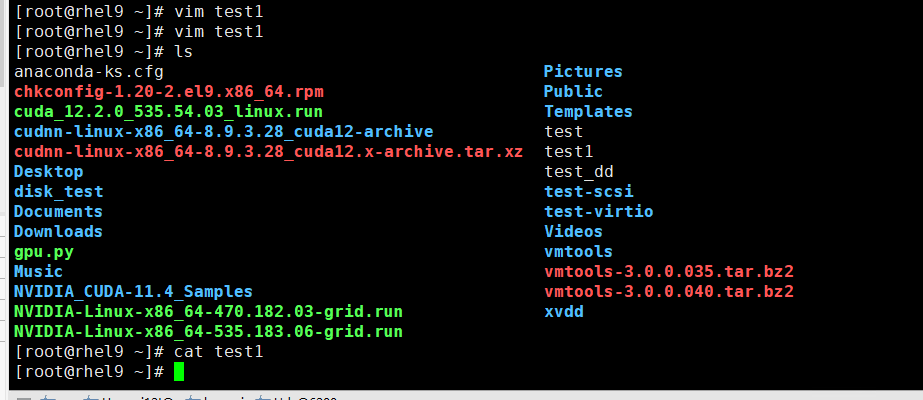 |
Conclusion | Passed |
Remarks |
3.10.4 Generating an Initial Password When Customization Is Not Used
Objective | Verify that the initial password can be generated when customization is not used. |
Networking | Networking diagram for verifying functions |
Prerequisites | 1. A guest OS VM to be tested has been created and VMTools corresponding to the SIA has been installed on the VM. 2. The VM has been converted to a template. |
Procedure | 1. Choose Resource Pool > VM Templates. Right-click the VM template and choose Deploy VM Using Template from the shortcut menu. In the displayed box, configure parameters in Basic Information and Configure VM. Then, in the Customize OS step, select Do not customize and select Generate Initial Password. (Expected result 1) 2. After the VM is started, select the VM, click the Summary tab to view the initial system password. Then, use the password to log in to the VM. (Expected result 2) 3. View the NIC configuration information (IP address, mask, gateway, and DNS server) of the VM. (Expected result 3) 4. Ping the IPv4 address of the VM from the local host. (Expected result 4) |
Expected Result | 1. The VM is successfully deployed using the template. 2. You can log in to the OS using the initial password. 3. The customized NIC information is the same as that in the original template, and the IP address can be pinged locally. 4. The IP address can be pinged locally. |
Test Result | 1. Choose Resource Pool > VM Templates. Right-click the VM template and choose Deploy VM Using Template from the shortcut menu. In the displayed box, configure parameters in Basic Information and Configure VM. Then, in the Customize OS step, select Do not customize and select Generate Initial Password. (Expected result 1) 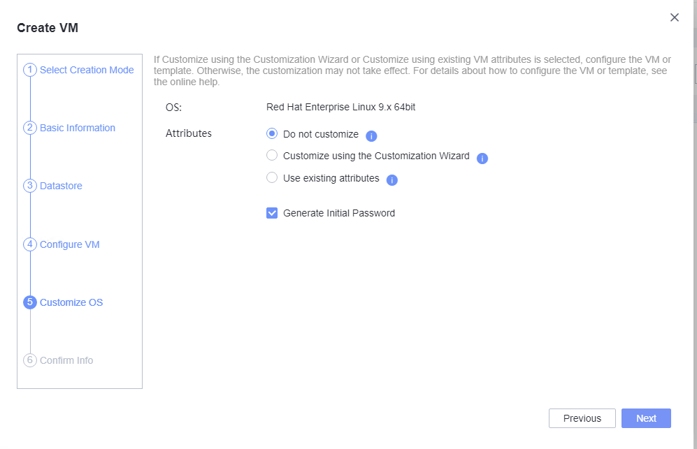 2. After the VM is started, select the VM, click the Summary tab to view the initial system password. Then, use the password to log in to the VM. (Expected result 2)  3. View the NIC configuration information (IP address, mask, gateway, and DNS server) of the VM. (Expected result 3) 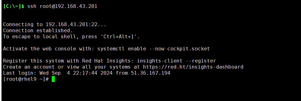 4. Ping the IPv4 address of the VM from the local host. (Expected result 4) 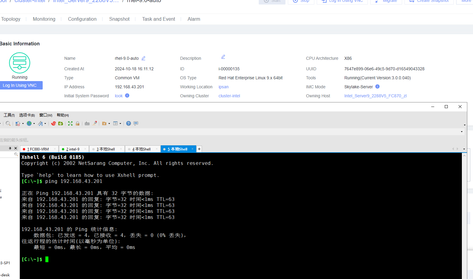

|
Conclusion |
|
Remarks |
3.11 USB Passthrough
3.11.1 Verifying the USB Passthrough Function of a VM
Objective | Verify that the USB passthrough function of a VM can be used properly. |
Networking | Networking diagram for verifying functions |
Prerequisites | 1. FusionCompute is running properly. 2. A USB device is available on the host. 3. The VM running the OS to be tested resides on the host that contains a USB device. 4. The USB device to be attached must support USB 2.0 or USB 3.0. Hygon and Phytium servers do not support USB 2.0. |
Procedure | 1. Log in to the FusionCompute portal. On the host that contains a USB device, select the CNA host and choose Configuration > Hardware > USB Device > Bind VM, set the controller type to USB 3.0, and select the corresponding VM. 2. Log in to the VM using VNC, mount the USB device to the specified directory (if the USB device does not have a file system, partition and format the USB device first), and perform read and write operations on the USB device. 3. Select the host, choose Configuration > Hardware > USB Device, and check the allocation status, device status, and owning VM. 4. Detach the USB device from the VM and log in to the VM using VNC to check whether the USB information is displayed. 5. Select the VM, choose Configuration > Hardware > USB Device, and check the USB information. 6. Log in to the FusionCompute portal. On the host that contains a USB device, select the CNA host and choose Configuration > Hardware > USB Device > Bind VM, set the controller type to USB 2.0, and select the corresponding VM. (Expected result 1) 7. Repeat steps 2 to 5. (Expected results 2 to 5) |
Expected Result | 1. The USB device is successfully attached to the VM. 2. After logging in to the system using VNC and mounting the USB device to specific directory, you can perform read and write operations on the USB device. 3. The allocation status is allocated, the device status is passthrough, and the owning VM is the VM to which the USB device is attached. 4. The USB device is detached from the VM and cannot be viewed on the VM. 5. The USB device information is empty. |
Test Result | 1. Log in to the FusionCompute portal. On the host that contains a USB device, select the CNA host and choose Configuration > Hardware > USB Device > Bind VM, set the controller type to USB 3.0, and select the corresponding VM. 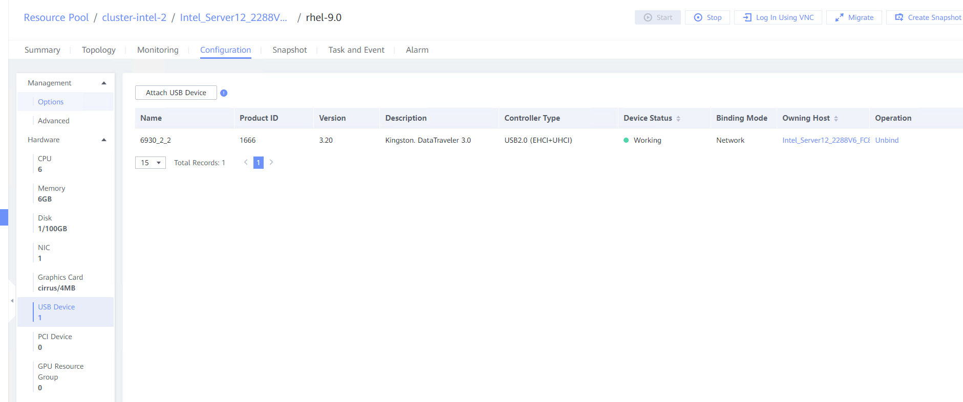 2. Log in to the VM using VNC, mount the USB device to the specified directory (if the USB device does not have a file system, partition and format the USB device first), and perform read and write operations on the USB device. 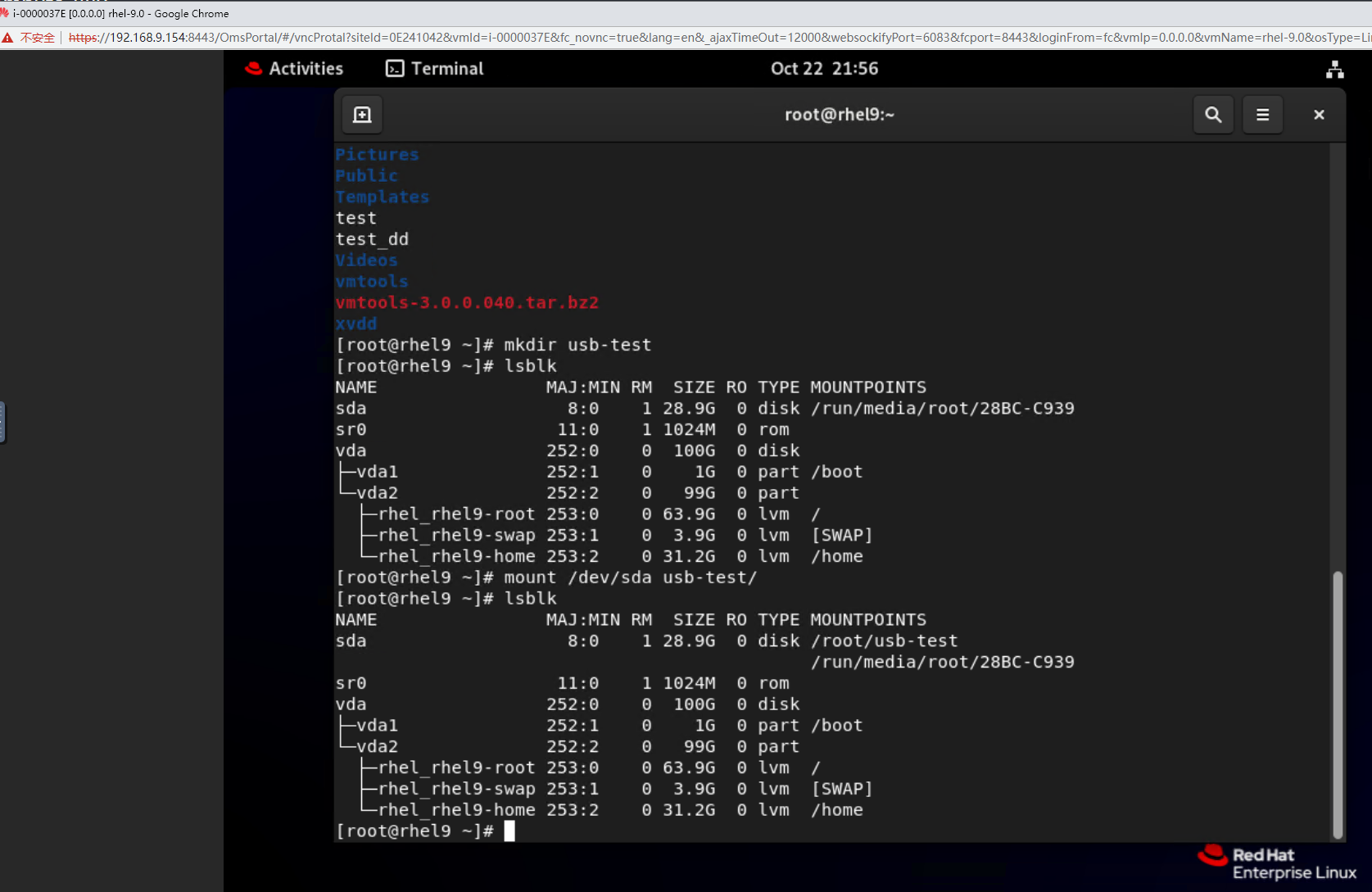 3. Select the host, choose Configuration > Hardware > USB Device, and check the allocation status, device status, and owning VM. 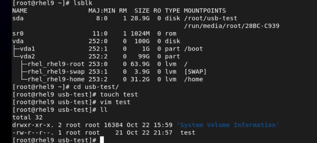 4. Detach the USB device from the VM and log in to the VM using VNC to check whether the USB information is displayed. 
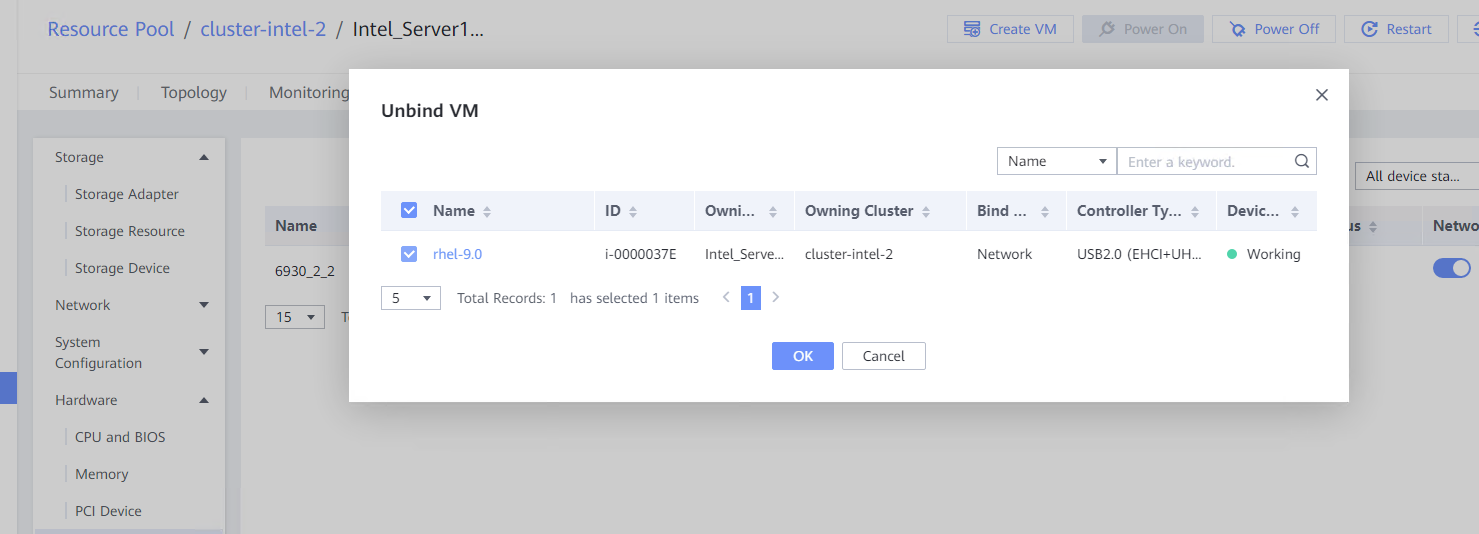 6. Log in to the FusionCompute portal. On the host that contains a USB device, select the CNA host and choose Configuration > Hardware > USB Device > Bind VM, set the controller type to USB 2.0, and select the corresponding VM. (Expected result 1) 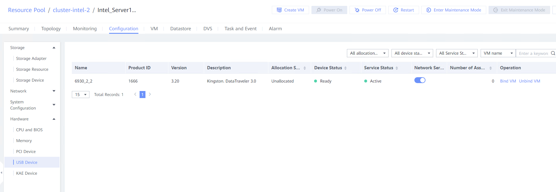 7. Repeat steps 2 to 5. (Expected results 2 to 5) 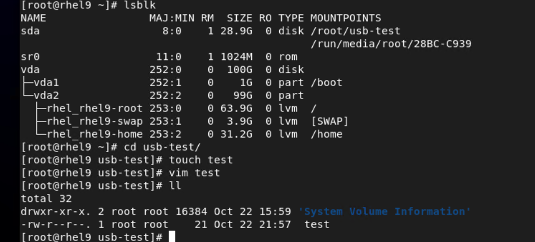
|
Conclusion |
|
Remarks |
3.12 SSD
3.12.1 Binding or Unbinding an SSD from a VM
Objective | Verify that a Solid State Disk (SSD) can be bound to or unbound from a VM. |
Networking | Networking diagram for verifying functions |
Prerequisites | 1. FusionCompute has been installed and deployed, and is running properly. You can log in to FusionCompute successfully. 2. An SSD card exists on the CNA host. |
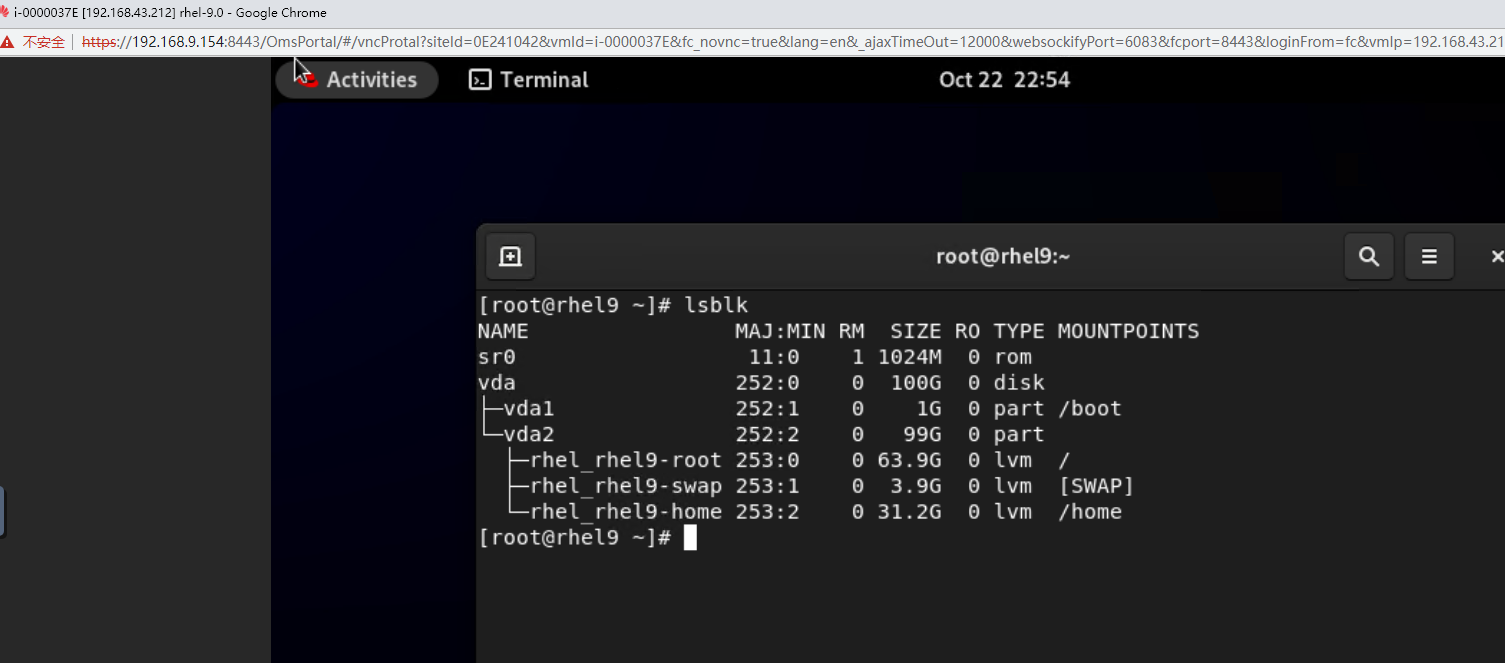
Procedure | 1. Choose VM > Configuration > Management > Advanced > Bind to Host, enable Bind to Host, and select the host corresponding to the VM. 2. Choose VM > Configuration > Hardware > Memory, and set Reserved (MB) to 6144. Set Memory to 6 GB, Quota to Medium, and Hugepage Memory to Disabled. 3. Power off the VM. 4. Choose VM > Configuration > Hardware > PCI Device > Bind PCI Device to bind an SSD. 5. Start the VM to which the SSD is bound. 6. Log in to the VM using VNC, mount the SSD, and run the lsblk command to query the SSD. The SSD name is nvme0n1. After the SSD is formatted, create a file on the SSD and reset the VM. (Expected result 6) 7. Choose VM > Configuration > Hardware > PCI Device to unbind the SSD. |
Expected Result | 1. The VM is successfully bound to the host. 2. The VM memory is configured successfully. 3. The VM is powered off successfully. 4. The PCI device is bound successfully. 5. The VM is powered on, and the corresponding record is displayed in the task list. 6. Choose VM > Configuration > Hardware > PCI Device to view the bound SSD. The device type is SSD. After the VM is restarted, the file created on the SSD is not lost. 7. The SSD is unbound from the VM. The lsblk command output in the VNC background shows that the SSD is unbound from the VM. |
Test Result | 3. Power off the VM. 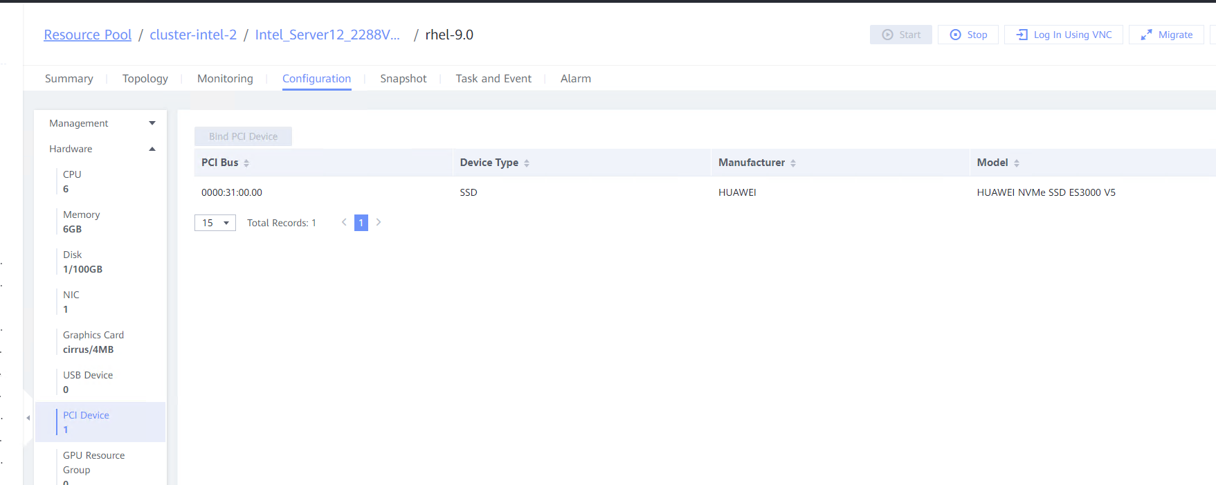 4. Choose VM > Configuration > Hardware > PCI Device > Bind PCI Device to bind an SSD. 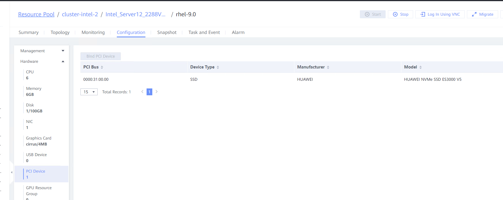
 5. Start the VM to which the SSD is bound. 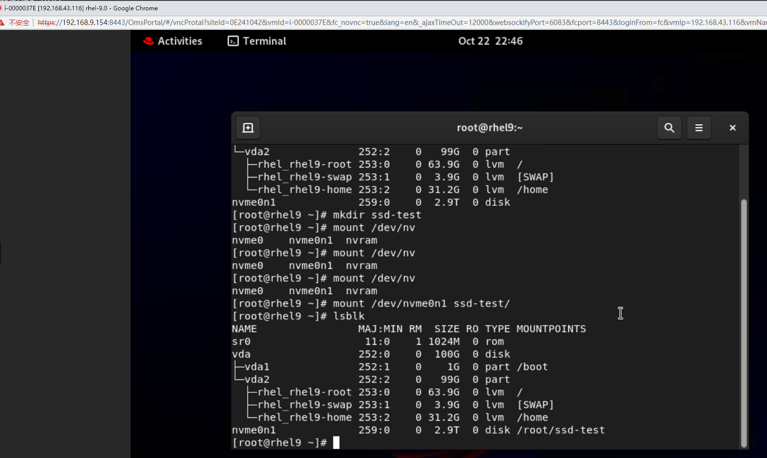 6. Log in to the VM using VNC, mount the SSD, and run the lsblk command to query the SSD. The SSD name is nvme0n1. After the SSD is formatted, create a file on the SSD and reset the VM. (Expected result 6) 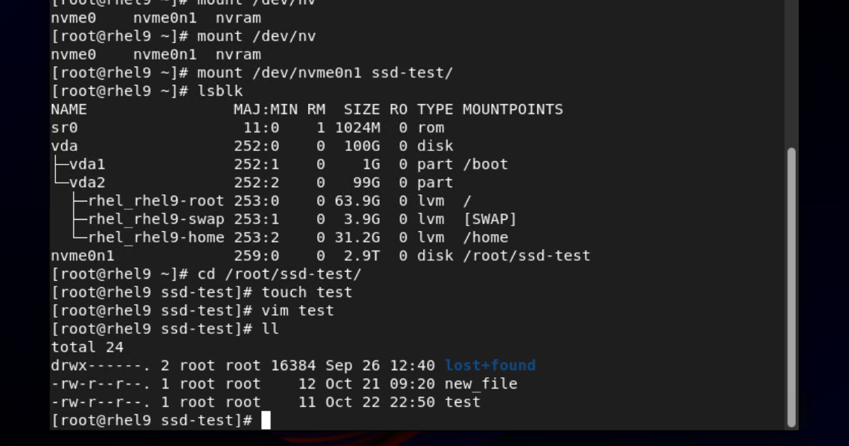

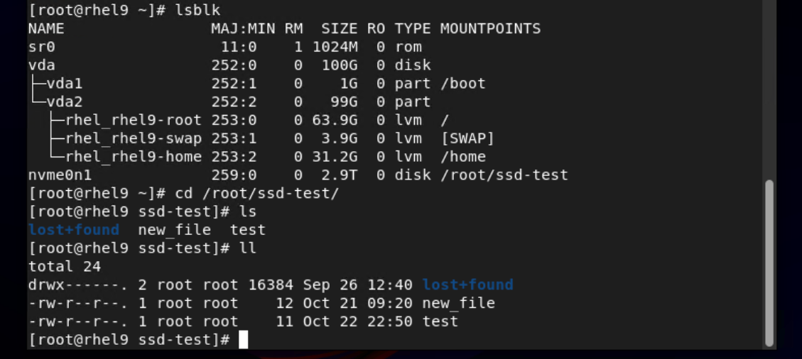 7. Choose VM > Configuration > Hardware > PCI Device to unbind the SSD. 
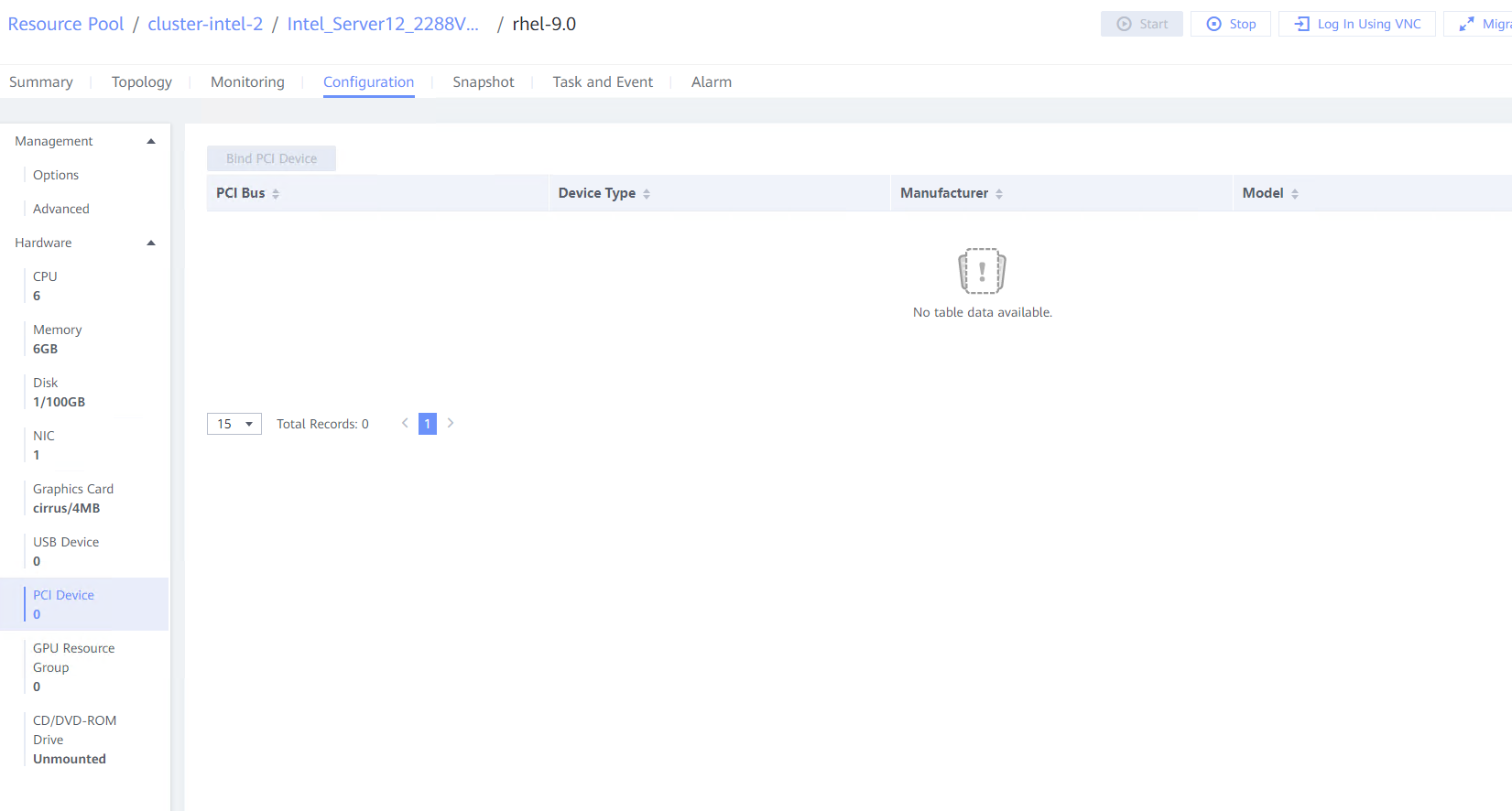
|
Conclusion |
|
Remarks |
3.13 GPU
3.13.1 Testing Basic GPU Functions of the Guest OS Passthrough GPU Device in the Linux System
Objective | Verify that the basic GPU functions are normal in the guest OS passthrough GPU device of the Linux system. |
Networking | Networking diagram for verifying functions |
Prerequisites | 1. GPUs (such as NVIDIA and Huawei GPUs) have been installed on the server. 2. Driver requirements: NVIDIA GPUs use the GRID 13.7 driver, Atlas GPUs use the Ascend HDK 22.0.0.2 driver, and other GPUs use the driver versions recommended by vendors. 3. For NVIDIA GPUs, CUDA, cuDNN, and TensorFlow have been installed on the VM, where computing scripts can be executed. 4. You have selected the VM to which the GPUs are to be bound and chosen Configuration > Hardware > Memory to set the maximum value for the reserved memory. The VM has been bound to the host. 5. Note: The Arm architecture (Kunpeng server) does not support GPU virtualization and supports only GPU passthrough. |
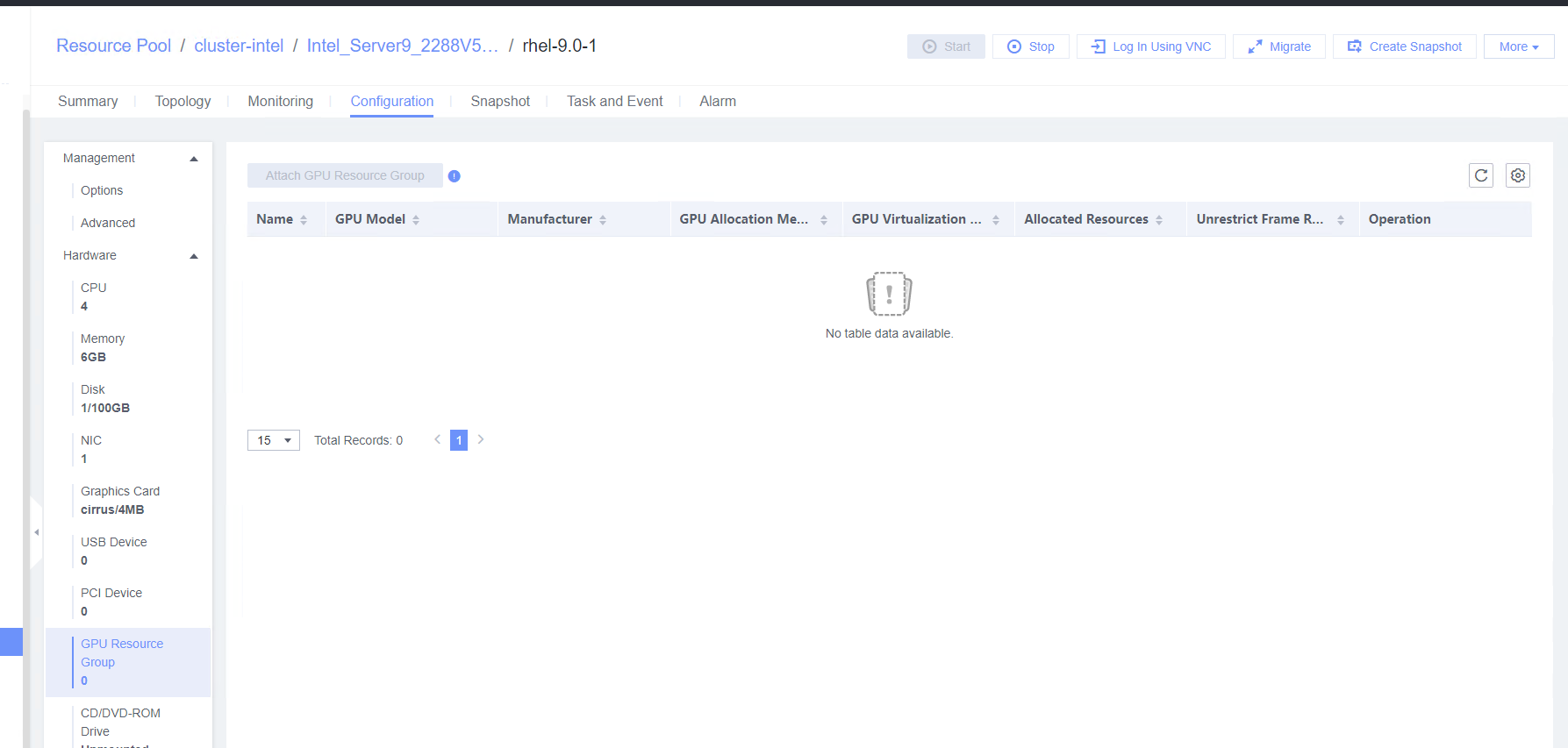
Procedure | 1. In the address box of a local browser, enter http://VRM floating IP address to log in to FusionCompute. (Expected result 1) 2. Choose Resource Pool > GPU Resource Groups > Create GPU Resource Group, set GPU Model to the GPU corresponding to the device and GPU Allocation Method to Passthrough, and click OK. (Expected result 2) 3. Choose GPU Resource Groups > GPUs > Attach GPU and select the GPU device. (Expected result 3) 4. Power off the VM, select the VM to be tested, choose Configuration > Hardware > GPU Resource Group > Attach GPU Resource Group, and select the corresponding GPU. (Expected result 4) 5. Log in to the VM and view the GPU information. (Expected result 5) (1) Run the lspci | grep -i nvidia and nvidia-smi commands to view NVIDIA GPU information. (2) Run the lspci | grep -i huawei and npu-smi info commands to view the Huawei GPU information. 6. Run the computing script on the VM with NVIDIA GPUs. (Expected result 6) 7. Unbind a GPU: Select the VM and choose Configuration > Hardware > GPU Resource Group > Detach. (Expected result 7) |
Expected Result | 1. The login to FusionCompute is successful. 2. The GPU resource group is created successfully. 3. The GPU device is successfully bound to the GPU resource group. 4. The GPU is successfully attached to the VM. 5. The GPU mode and version queried in the background are the same as the actual ones. 6. The computing script is executed successfully, and the GPU usage increases significantly. 7. The GPU is unbound successfully, and the query result of the nvidia-smi command is empty. |
Test Result | 2. Choose Resource Pool > GPU Resource Groups > Create GPU Resource Group, set GPU Model to the GPU corresponding to the device and GPU Allocation Method to Passthrough, and click OK. (Expected result 2) 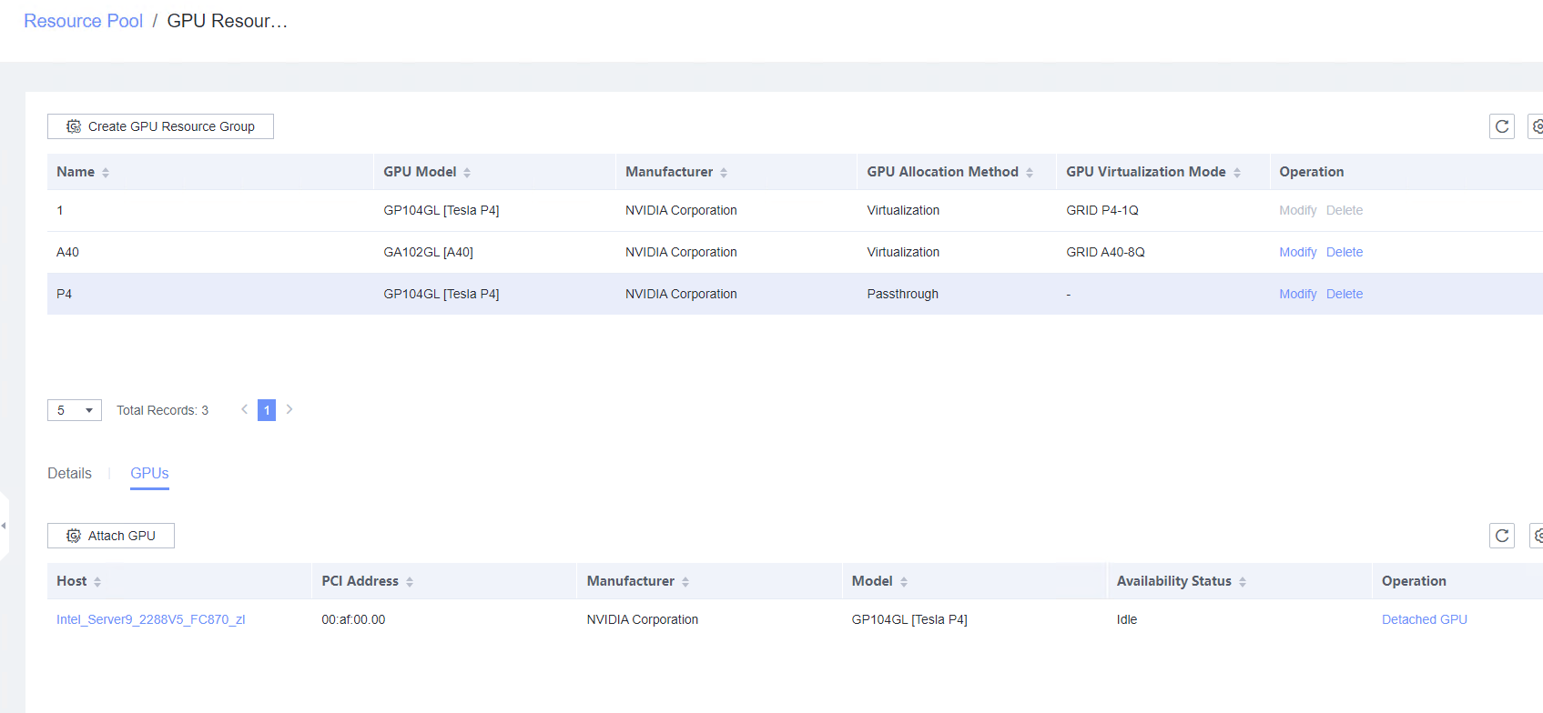 3. Choose GPU Resource Groups > GPUs > Attach GPU and select the GPU device. (Expected result 3) 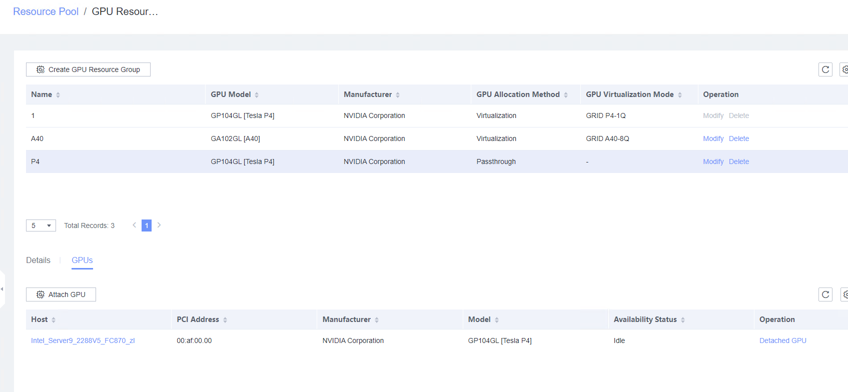 4. Power off the VM, select the VM to be tested, choose Configuration > Hardware > GPU Resource Group > Attach GPU Resource Group, and select the corresponding GPU. (Expected result 4) 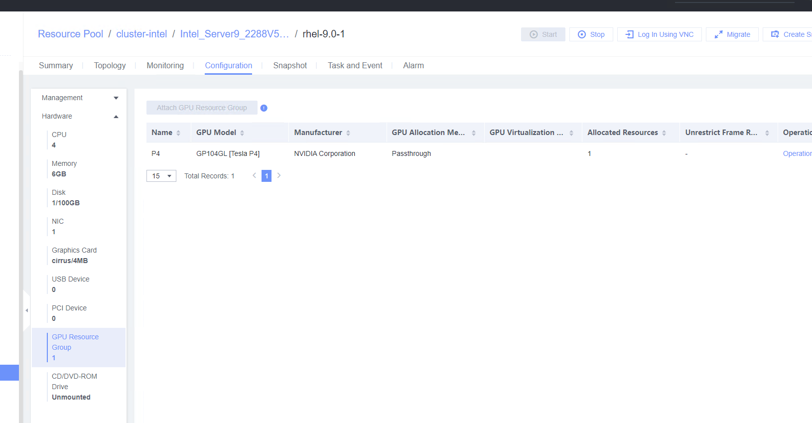 5. Log in to the VM and view the GPU information. (Expected result 5) (1) Run the lspci | grep -i nvidia and nvidia-smi commands to view NVIDIA GPU information. (2) Run the lspci | grep -i huawei and npu-smi info commands to view the Huawei GPU information. 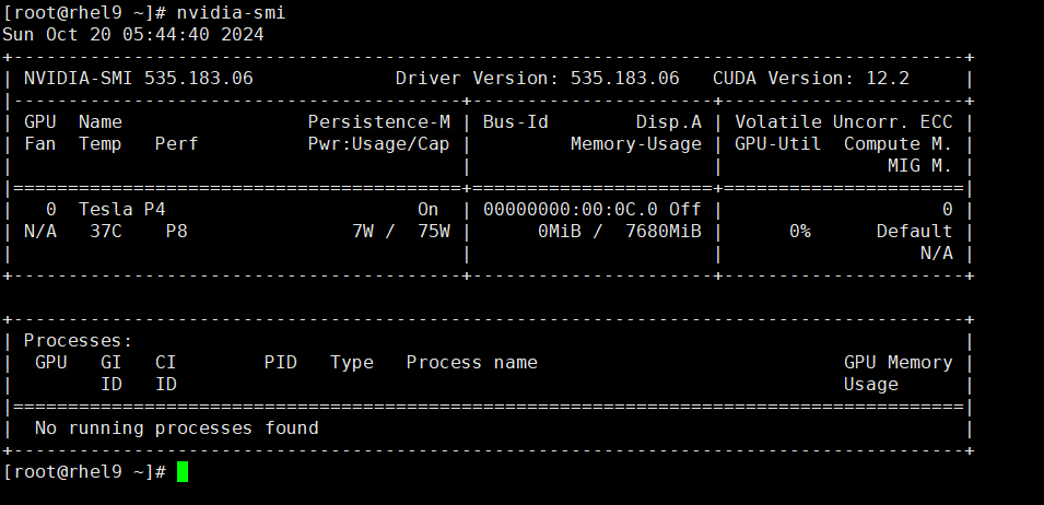 6. Run the computing script on the VM with NVIDIA GPUs. (Expected result 6) 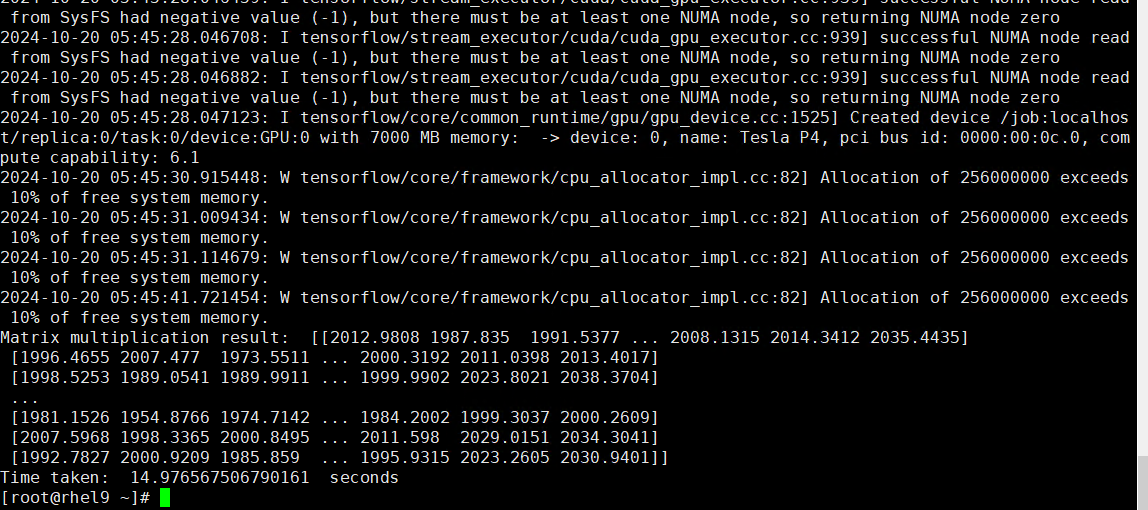 7. Unbind a GPU: Select the VM and choose Configuration > Hardware > GPU Resource Group > Detach. (Expected result 7) 

|
Conclusion |
|
Remarks |
3.12.2 Testing the Basic vGPU Functions of the Guest OS vGPU Device in the Linux System
Objective | Verify that basic vGPU functions are normal in the guest OS vGPU device in the Linux system. |
Networking | Networking diagram for verifying functions |
Prerequisites | 1. GPUs (such as NVIDIA and Huawei GPUs) have been installed on the server. 2. Driver requirements: NVIDIA GPUs use the GRID 13.7 driver, Atlas GPUs use the Ascend HDK 22.0.0.2 driver, and other GPUs use the driver versions recommended by vendors. 3. For NVIDIA GPUs, CUDA, cuDNN, and TensorFlow have been installed on the VM, and computing scripts can be executed. 4. You have selected the VM to which the GPUs are to be bound and chosen Configuration > Hardware > Memory to set the maximum value for the reserved memory. The VM has been bound to the host. 5. Note: The Arm architecture (Kunpeng server) does not support GPU virtualization and supports only GPU passthrough. |
Procedure | 1. In the address box of a local browser, enter http://VRM floating IP address to log in to FusionCompute. (Expected result 1) 2. Choose Resource Pool > GPU Resource Groups > Create GPU Resource Group, set GPU Model to the GPU corresponding to the device and GPU Allocation Method to Virtualization, and click OK. (Expected result 2) 3. Choose GPU Resource Groups > GPUs > Attach GPU and select the GPU device. (Expected result 3) 4. Power off the VM, select the VM to be tested, choose Configuration > Hardware > GPU Resource Group > Attach GPU Resource Group, and select the corresponding GPU. (Expected result 4) 5. Log in to the VM and check the vGPU information. For NVIDIA GPU cards, run the lspci | grep -i nvidia and nvidia-smi commands. (Expected result 5) 6. Run the computing script on the VM with NVIDIA vGPUs. (Expected result 6) 7. Unbind a GPU: Select the VM and choose Configuration > Hardware > GPU Resource Group > Detach. (Expected result 7) |
Expected Result | 1. The login to FusionCompute is successful. 2. The GPU resource group is created successfully. 3. The GPU device is successfully bound to the GPU resource group. 4. The GPU is successfully attached to the VM. 5. The NVIDIA GPU mode and version queried in the background are the same as the actual ones. 6. The computing script is executed successfully, and the vGPU usage increases significantly. 7. The GPU is unbound successfully, and the query result of the nvidia-smi command is empty. |
Test Result | 1. In the address box of a local browser, enter http://VRM floating IP address to log in to FusionCompute. (Expected result 1) 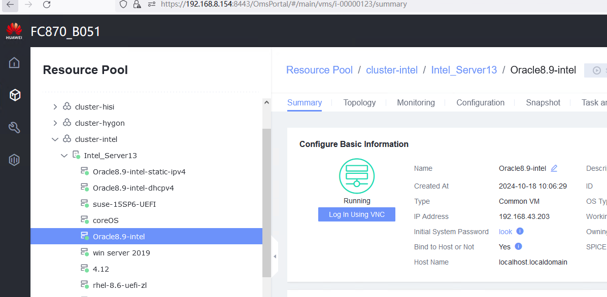 2. Choose Resource Pool > GPU Resource Groups > Create GPU Resource Group, set GPU Model to the GPU corresponding to the device and GPU Allocation Method to Virtualization, and click OK. (Expected result 2) 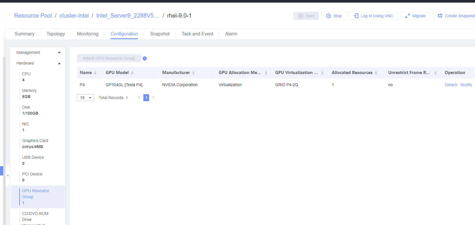 3. Choose GPU Resource Groups > GPUs > Attach GPU and select the GPU device. (Expected result 3) 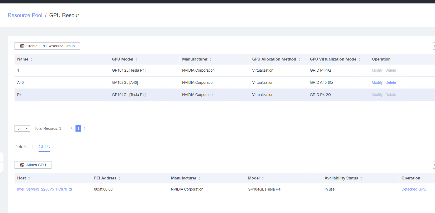 4. Power off the VM, select the VM to be tested, choose Configuration > Hardware > GPU Resource Group > Attach GPU Resource Group, and select the corresponding GPU. (Expected result 4) 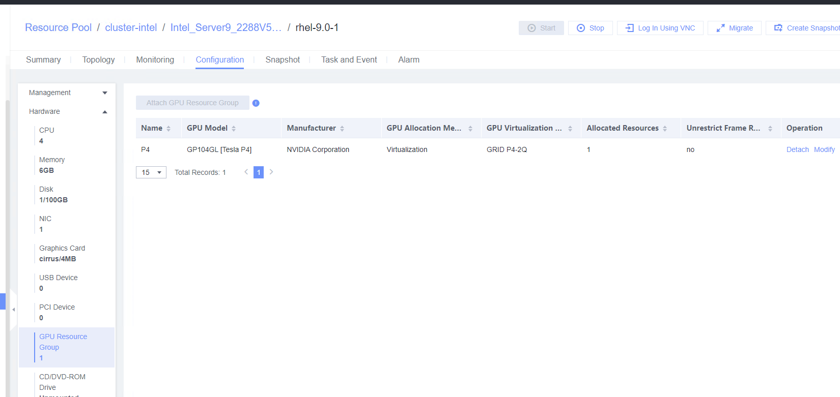 5. Log in to the VM and check the vGPU information. For NVIDIA GPU cards, run the lspci | grep -i nvidia and nvidia-smi commands. (Expected result 5) 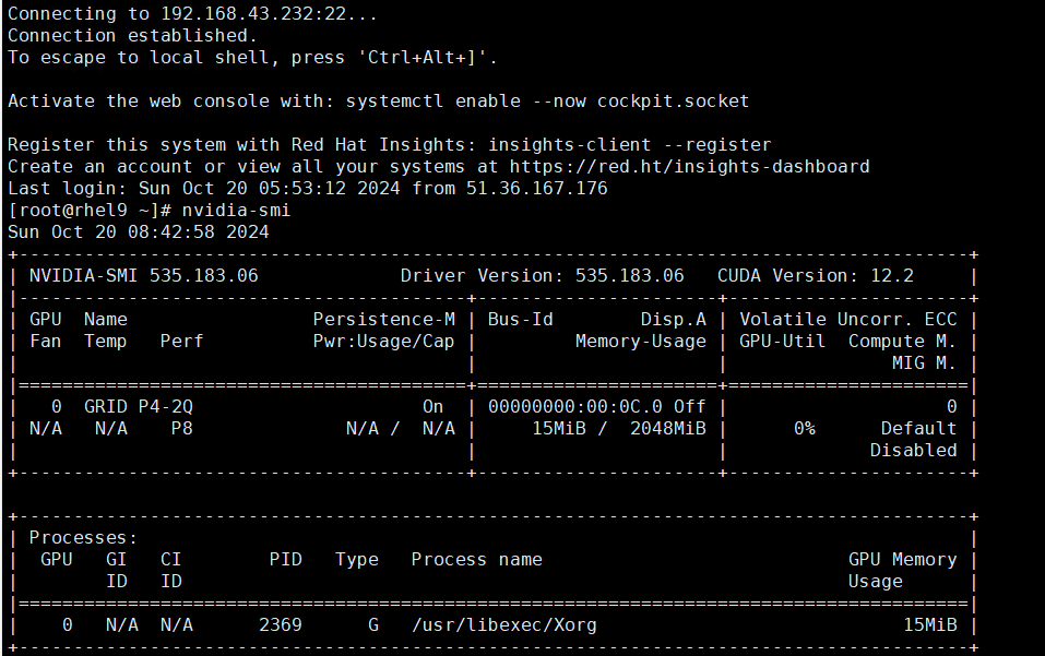 6. Run the computing script on the VM with NVIDIA vGPUs. (Expected result 6) 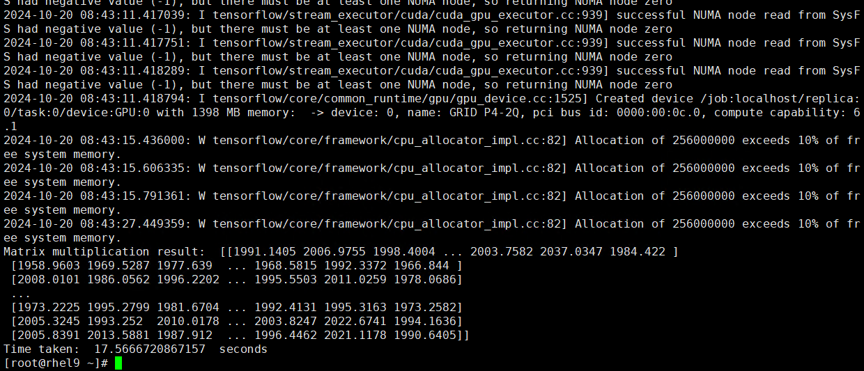 7. Unbind a GPU: Select the VM and choose Configuration > Hardware > GPU Resource Group > Detach. (Expected result 7) 

|
Conclusion |
|
Remarks |
3.14 Other Value-added Functions of the Guest OS
3.14.1 Testing NUMA Topology Adjustment
Objective | Verify that the NUMA topology adjustment is normal. |
Networking | Networking diagram for verifying functions |
Prerequisites | 1. FusionCompute has been installed and deployed and the system is running properly. You can log in to FusionCompute successfully. 2. A guest OS VM to be tested has been created and VMTools corresponding to the SIA has been installed on the VM. |
Procedure | 1. Select the VM to be tested, which is in the stopped state, choose Configuration > Management > Options > NUMA Topology Adjustment > Settings, enable NUMA topology adjustment, and set the adjustment mode to Auto Adjustment. (Expected result 1) 2. Select the VM, choose Configuration > Management > Advanced > NUMA Topology Adjustment > Settings, enable Generate on First Startup, and set the maximum number of CPUs per NUMA node to 2 and the minimum number of CPUs for NUMA node splitting to 1. Choose Hardware > CPU, set and the number of CPU cores to 4. (Expected result 2) 3. Start the VM and run the lscpu command to check the number of NUMA nodes on the VM. (Expected result 3) |
Expected Result | 1. NUMA topology adjustment is enabled successfully. 2. The advanced NUMA configuration is successful. 3. Two NUMA nodes are displayed. |
Test Result | 1. Select the VM to be tested, which is in the stopped state, choose Configuration > Management > Options > NUMA Topology Adjustment > Settings, enable NUMA topology adjustment, and set the adjustment mode to Auto Adjustment. (Expected result 1)  2. Select the VM, choose Configuration > Management > Advanced > NUMA Topology Adjustment > Settings, enable Generate on First Startup, and set the maximum number of CPUs per NUMA node to 2 and the minimum number of CPUs for NUMA node splitting to 1. Choose Hardware > CPU, set and the number of CPU cores to 4. (Expected result 2) 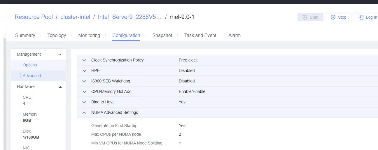 4. Start the VM and run the lscpu command to check the number of NUMA nodes on the VM. (Expected result 3) 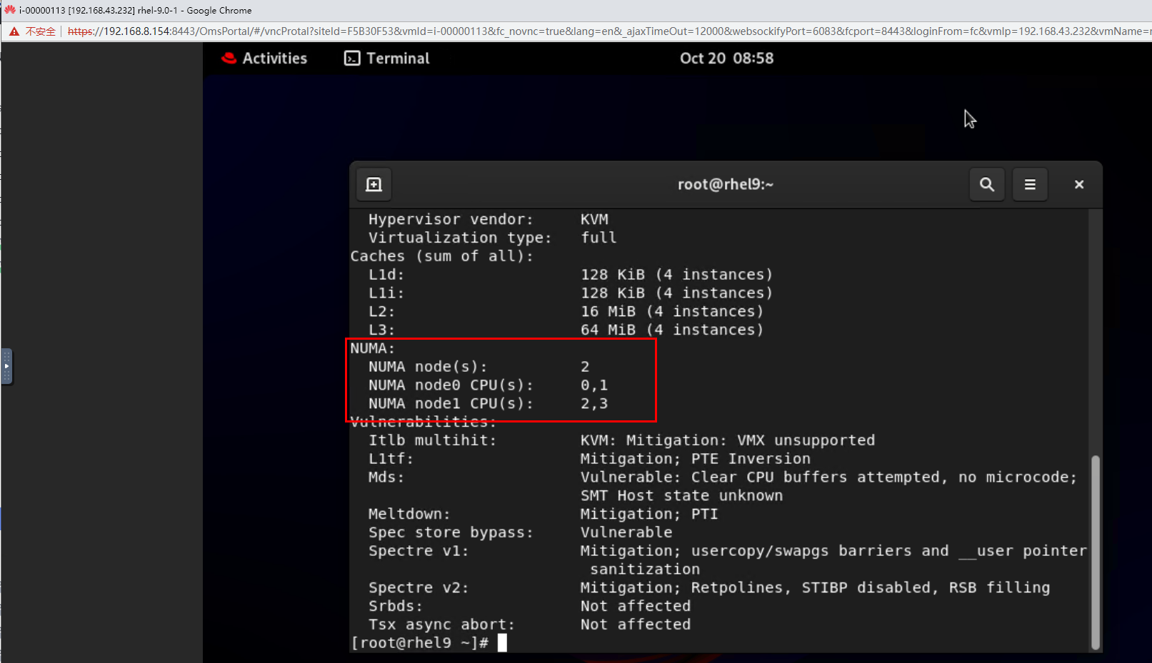 |
Conclusion |
|
Remarks |
3.14.2 Testing the I/O Suspension Function
Objective | Verify that the I/O suspension function is normal. |
Networking | Networking diagram for verifying functions |
Prerequisites | 1. FusionCompute has been connected to SAN storage, and the VM to be tested has been deployed on SAN storage. 2. A guest OS VM to be tested has been created and VMTools corresponding to the SIA has been installed on the VM. |
Procedure | 1. Select a VM, which is in the stopped state, choose Configuration > Management > Advanced > Policy Delay > Settings and set the customized delay time to 14400 minutes. (Expected result 1) 2. Add a SAN storage disk to the VM, format the disk and mount it to the specified directory, and create a test file test.txt. Run the dd command to write data to the file, for example, dd if=/dev/vdb of=./test.txt bs=8k count=300000. (Expected result 2) 3. Simulate a scenario where the storage link is disconnected. For example, log in to the storage device, delete the initiator (iSCSI) from the host corresponding to the VM, and check the VM status. (Expected result 3) 4. Restore the storage link: Add the initiator in step 3 and choose Resource Pool > Storage > Storage Devices > Scan on the FusionCompute page. (Expected result 4) |
Expected Result | 1. The policy delay is configured successfully. 2. Data is written properly. 3. The dd command is suspended, the VM status is normal, and no reset occurs. 4. After the storage link is restored, the datastore status of the host where the VM resides is associated, and the dd command is successfully executed. |
Test Result | 1. Select a VM, which is in the stopped state, choose Configuration > Management > Advanced > Policy Delay > Settings and set the customized delay time to 14400 minutes. (Expected result 1) 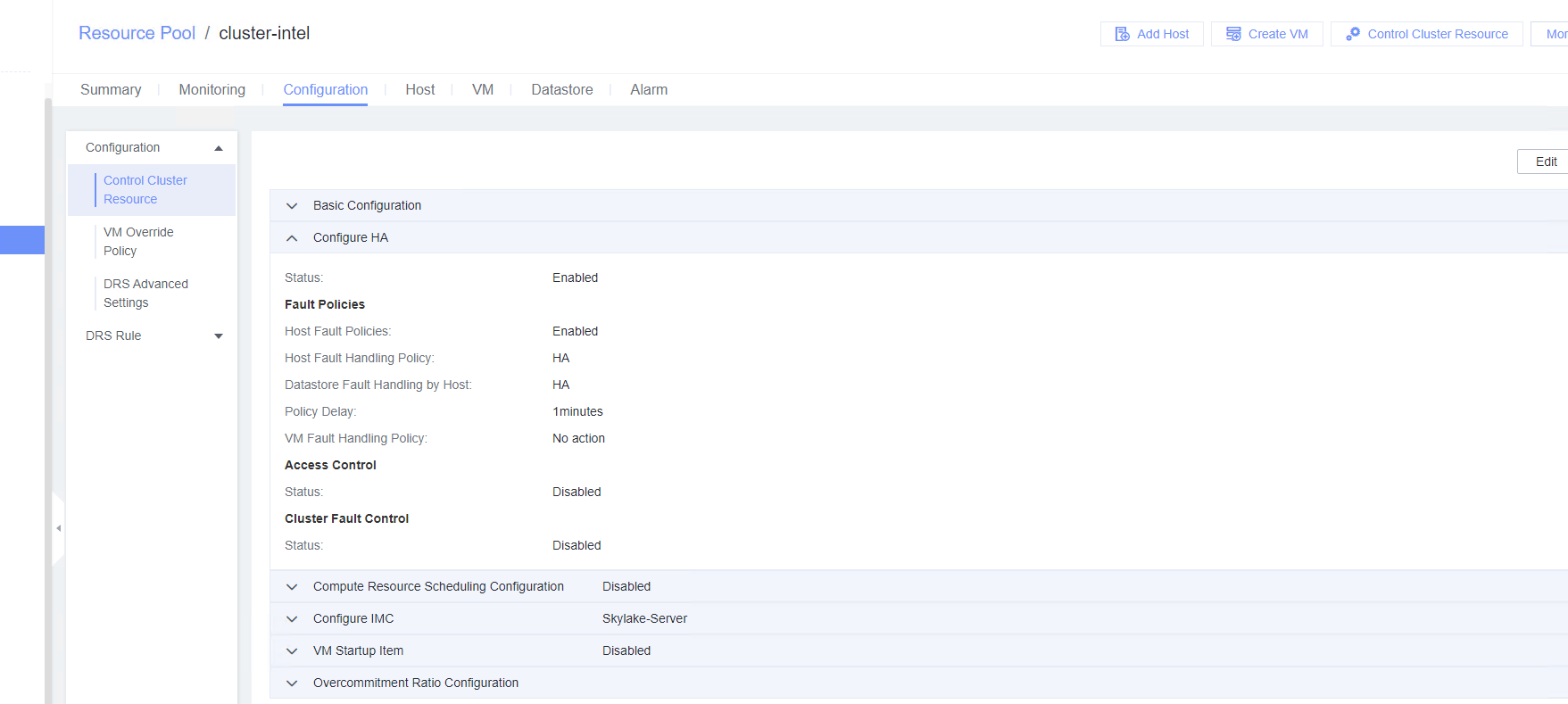 2. Add a SAN storage disk to the VM, format the disk and mount it to the specified directory, and create a test file test.txt. Run the dd command to write data to the file, for example, dd if=/dev/vdb of=./test.txt bs=8k count=300000. (Expected result 2) 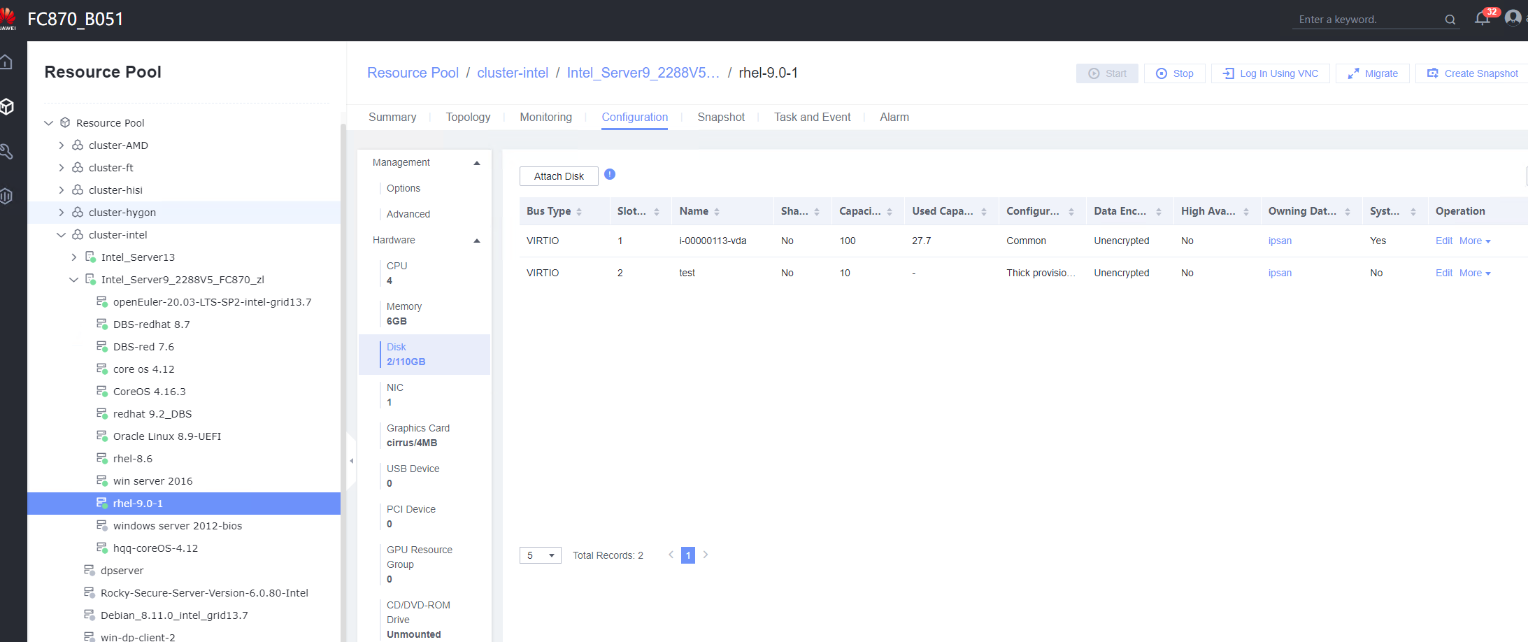 3. Simulate a scenario where the storage link is disconnected. For example, log in to the storage device, delete the initiator (iSCSI) from the host corresponding to the VM, and check the VM status. (Expected result 3) 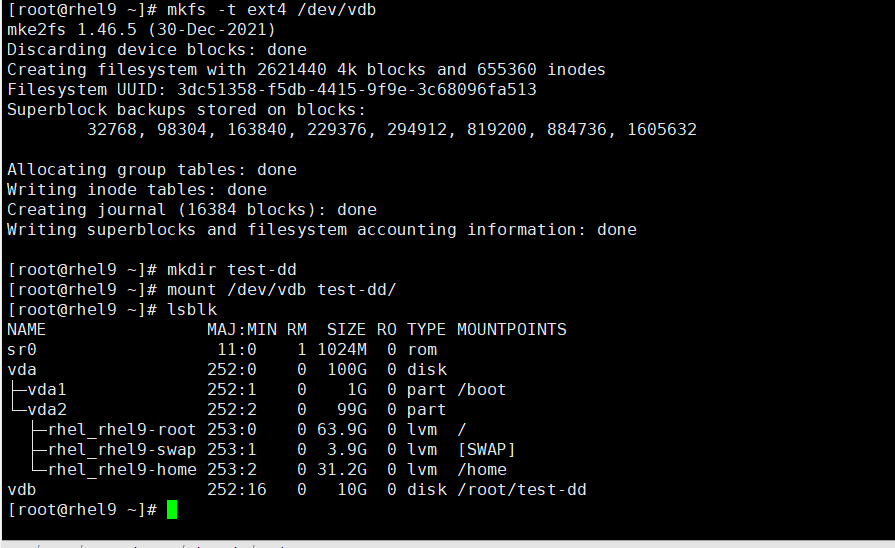
 4. Restore the storage link: Add the initiator in step 3 and choose Resource Pool > Storage > Storage Devices > Scan on the FusionCompute page. (Expected result 4) 


|
Conclusion |
|
Remarks |
3.14.3 Testing the CPU Cache Consistency Between the VM and the Host
Objective | Verify that the CPU cache of the VM is consistent with that of the host. |
Networking | Networking diagram for verifying functions |
Prerequisites | 1. FusionCompute has been installed and deployed, and is running properly. You can log in to FusionCompute successfully. 2. A guest OS VM to be tested has been created and VMTools corresponding to the SIA has been installed on the VM. 3. Note: The VM cache size at each level meets following requirements: for the Arm 64 version, L1d cache: 64 KB, L1i cache: 64 KB, L2 cache: 512 KB, and L3 cache: 32768 KB; for Intel, L1d cache: 32 KB, L1i cache: 32 KB, L2 cache: 4096 KB, and L3 cache: 16384 KB; for AMD and Hygon, L1d cache: 64 KB, L1i cache: 64K, L2 cache: 512 KB, and L3 cache: 16384 KB. |
Procedure | 1. Log in to the VM and run the lscpu command to query the cache size of each level. Divide the total cache size of each level by the number of threads. (Expected result 1) |
Expected Result | 1. The value of the cache size of each level divided by the number of threads of each level is equal to the value of the cache size of each level of the VM in prerequisite 3. |
Test Result | 1. Log in to the VM and run the lscpu command to query the cache size of each level. Divide the total cache size of each level by the number of threads. (Expected result 1) 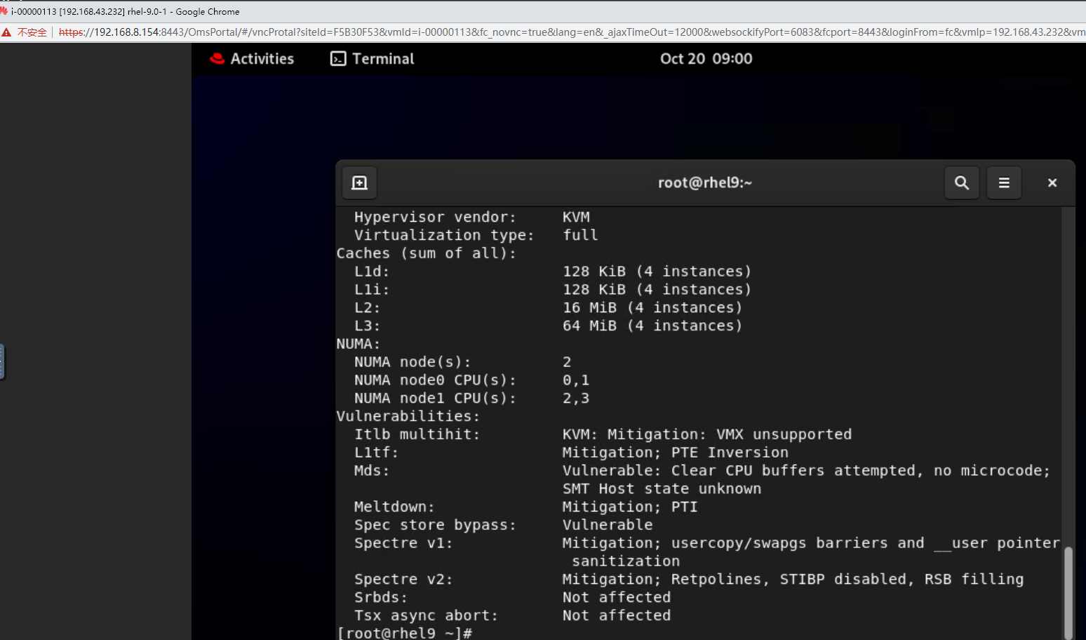
|
Conclusion |
|
Remarks |
3.15 Guest OS Basic Reliability Test
3.15.1 Testing the Customized IPv4 Configuration After the VM Is Repeatedly Reset
Objective | Verify that the customized IPv4 configuration is normal after the VM is repeatedly reset. |
Networking | Networking diagram for verifying functions |
Prerequisites | 1. A guest OS VM to be tested has been created and VMTools corresponding to the SIA has been installed on the VM. 2. The VM has been converted to a template. Before converting the VM to a template, run the cat /etc/resolv.conf command to check whether the DNS address is automatically obtained. If so, delete the automatically-obtained address from the resolv.conf file. (If the DNS address is not deleted, the accuracy of the automatically-obtained DNS address will be affected during template deployment.) 3. An IPv4 DHCP server has been configured on the network where the VM resides. |
Procedure | 1. Choose Resource Pool > VM Templates. Right-click the VM template and choose Deploy VM Using Template. In the displayed box, configure parameters in Basic Information and Configure VM. Then, in the Customize OS tab page, select Customize using the Customization Wizard, configure Computer Name and Administrator Password, and set the Network resource management type to Workgroup and Network resource management name to workgroup name. (Expected result 1) 2. Customize NIC settings, set IP type to IPv4, configure the IP address and subnet mask, enable IPv4 route information, and configure the IPv4 route gateway, IPv4 destination network, IPv4 destination network mask, primary DNS server address (for example, 8.8.8.8), and secondary DNS server address (for example, 114.114.114.114). (Expected result 2) 3. Forcibly reset the VM for three times. After each VM startup, check whether the customized information in steps 1 and 2 is lost or changed. (Expected result 3) |
Expected Result | 1. The customized attributes are correctly configured. 2. The customized NIC configuration is normal, and the VM is successfully deployed using the template. 3. The customized information in steps 1 and 2 is not lost or changed. The login to the VM using SSH (Linux OS) or remote desktop (Windows) is successful. |
Test Result | 1. Choose Resource Pool > VM Templates. Right-click the VM template and choose Deploy VM Using Template. In the displayed box, configure parameters in Basic Information and Configure VM. Then, in the Customize OS tab page, select Customize using the Customization Wizard, configure Computer Name and Administrator Password, and set the Network resource management type to Workgroup and Network resource management name to workgroup name. (Expected result 1) 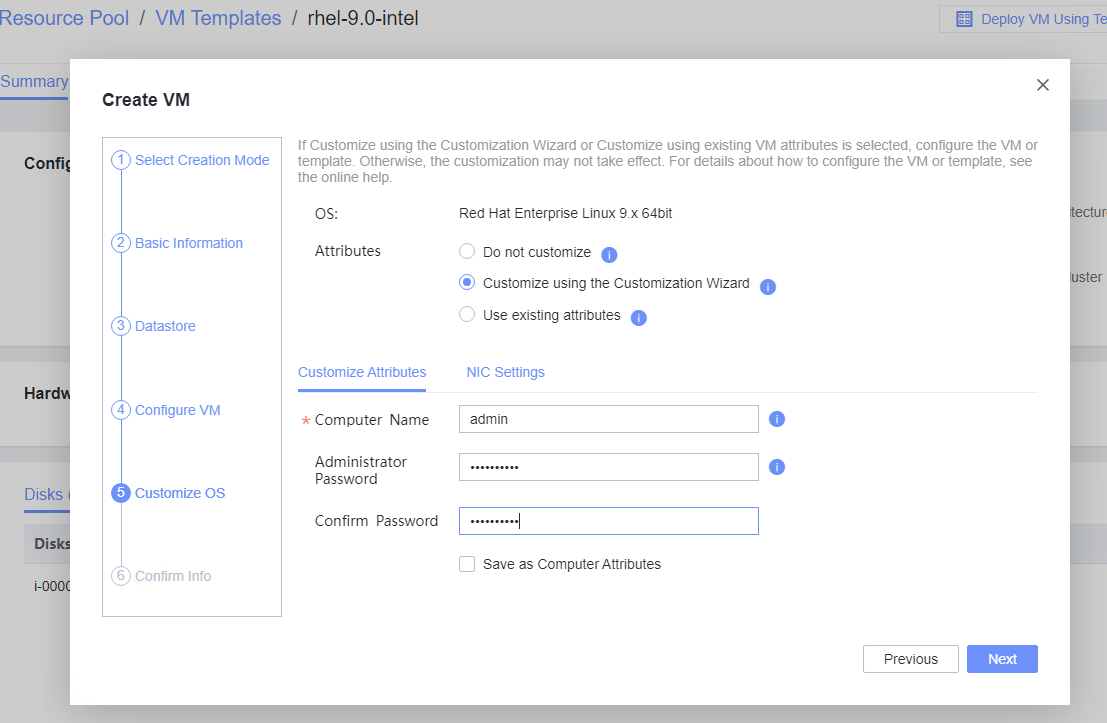
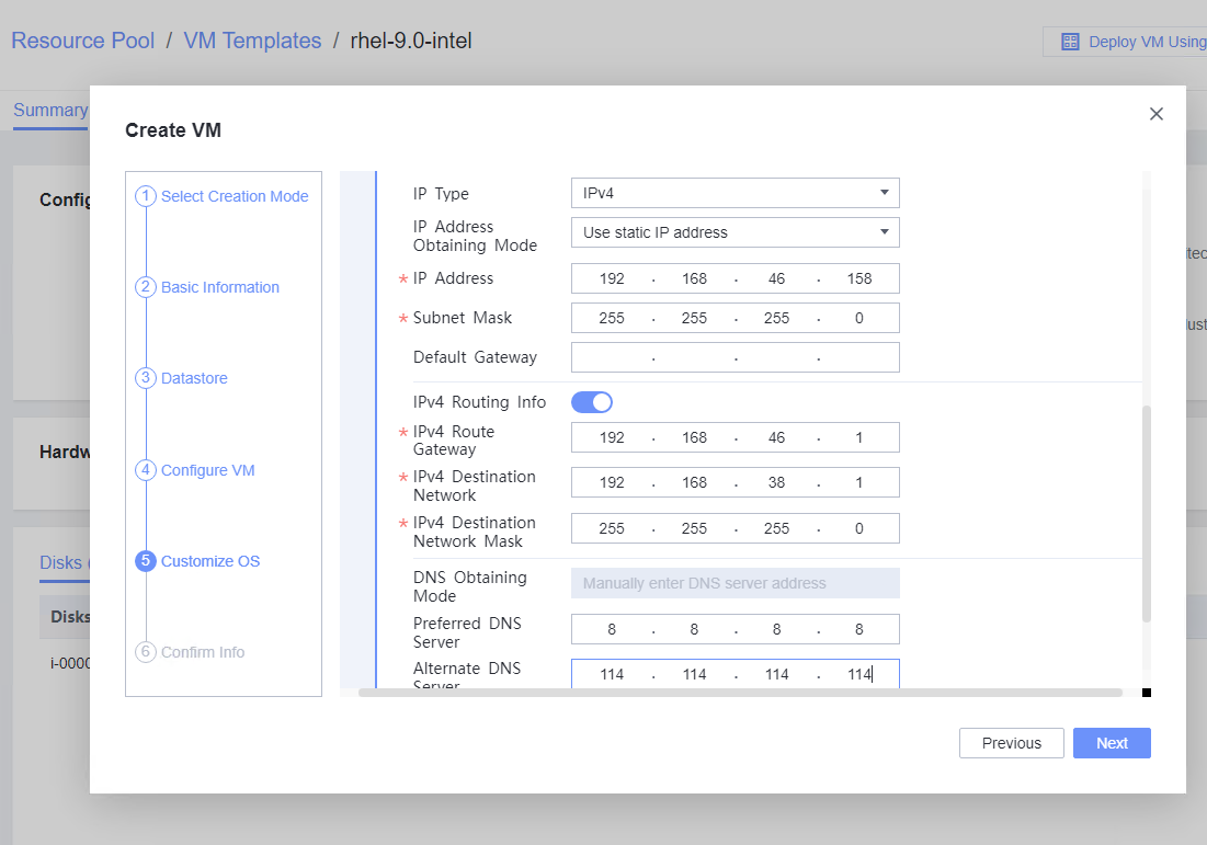 2. Customize NIC settings, set IP type to IPv4, configure the IP address and subnet mask, enable IPv4 route information, and configure the IPv4 route gateway, IPv4 destination network, IPv4 destination network mask, primary DNS server address (for example, 8.8.8.8), and secondary DNS server address (for example, 114.114.114.114). (Expected result 2) 
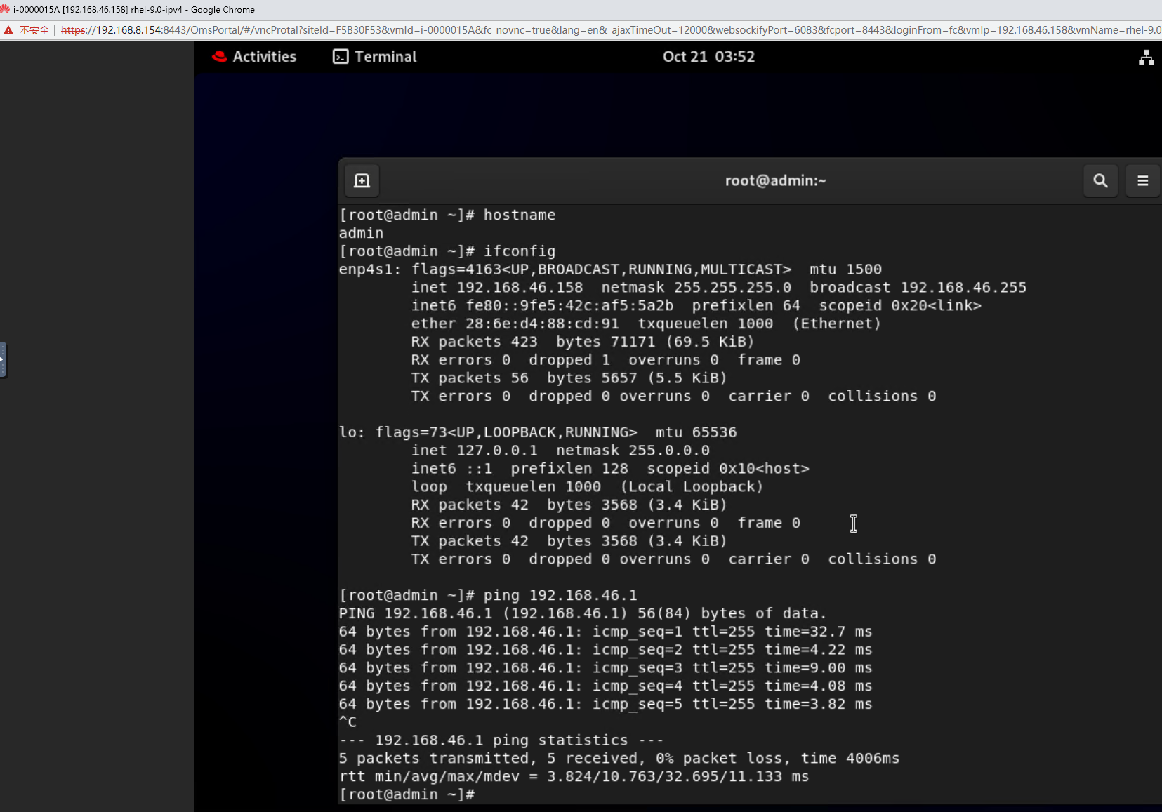 3. Forcibly reset the VM for three times. After each VM startup, check whether the customized information in steps 1 and 2 is lost or changed. (Expected result 3) 

|
Conclusion |
|
Remarks |
3.15.2 Testing the Customized IPv6 Configuration After the VM Is Repeatedly Reset
Objective | Verify that the customized IPv6 configuration is normal after the VM is repeatedly reset. |
Networking | Networking diagram for verifying functions |
Prerequisites | 1. A guest OS VM to be tested has been created and VMTools corresponding to the SIA has been installed on the VM. 2. The VM has been converted to a template. Before converting the VM to a template, run the cat /etc/resolv.conf command to check whether the DNS address is automatically-obtained. If so, delete the automatically-obtained address from the resolv.conf file. (If the DNS address is not deleted, the accuracy of the automatically-obtained DNS address during template deployment will be affected.) |
Procedure | 1. Choose Resource Pool > VM Templates. Right-click the VM and choose Deploy VM Using Template > Basic Information > Configure VM. In the Customize OS tab page, select Customize using the Customization Wizard and set the computer name and administrator password, and set the VM attribute specification name. (Expected result 1) 2. Customize NIC settings, set IP Type to IPv6 and IP Address Obtaining Mode to Use static IPv6 address, and enter the IP address and subnet prefix length. Enable IPv6 route information, configure the IPv6 route gateway, IPv6 destination network, and IPv6 destination network prefix length, and set the primary and secondary DNS server addresses. (Expected result 2) 3. Forcibly reset the VM for three times. After each VM startup, check whether the customized information in steps 1 and 2 is lost or changed. (Expected result 3) |
Expected Result | 1. The customized attributes are correctly configured. 2. The customized NIC configuration is normal, and the VM is successfully deployed using the template. 3. The customized information in steps 1 and 2 is not lost or changed. The login to the VM using SSH (Linux OS) or remote desktop (Windows) is successful. |
Test Result | 1. Choose Resource Pool > VM Templates. Right-click the VM and choose Deploy VM Using Template > Basic Information > Configure VM. In the Customize OS tab page, select Customize using the Customization Wizard and set the computer name and administrator password, and set the VM attribute specification name. (Expected result 1) 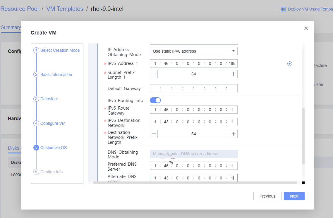 2. Customize NIC settings, set IP Type to IPv6 and IP Address Obtaining Mode to Use static IPv6 address, and enter the IP address and subnet prefix length. Enable IPv6 route information, configure the IPv6 route gateway, IPv6 destination network, and IPv6 destination network prefix length, and set the primary and secondary DNS server addresses. (Expected result 2) 
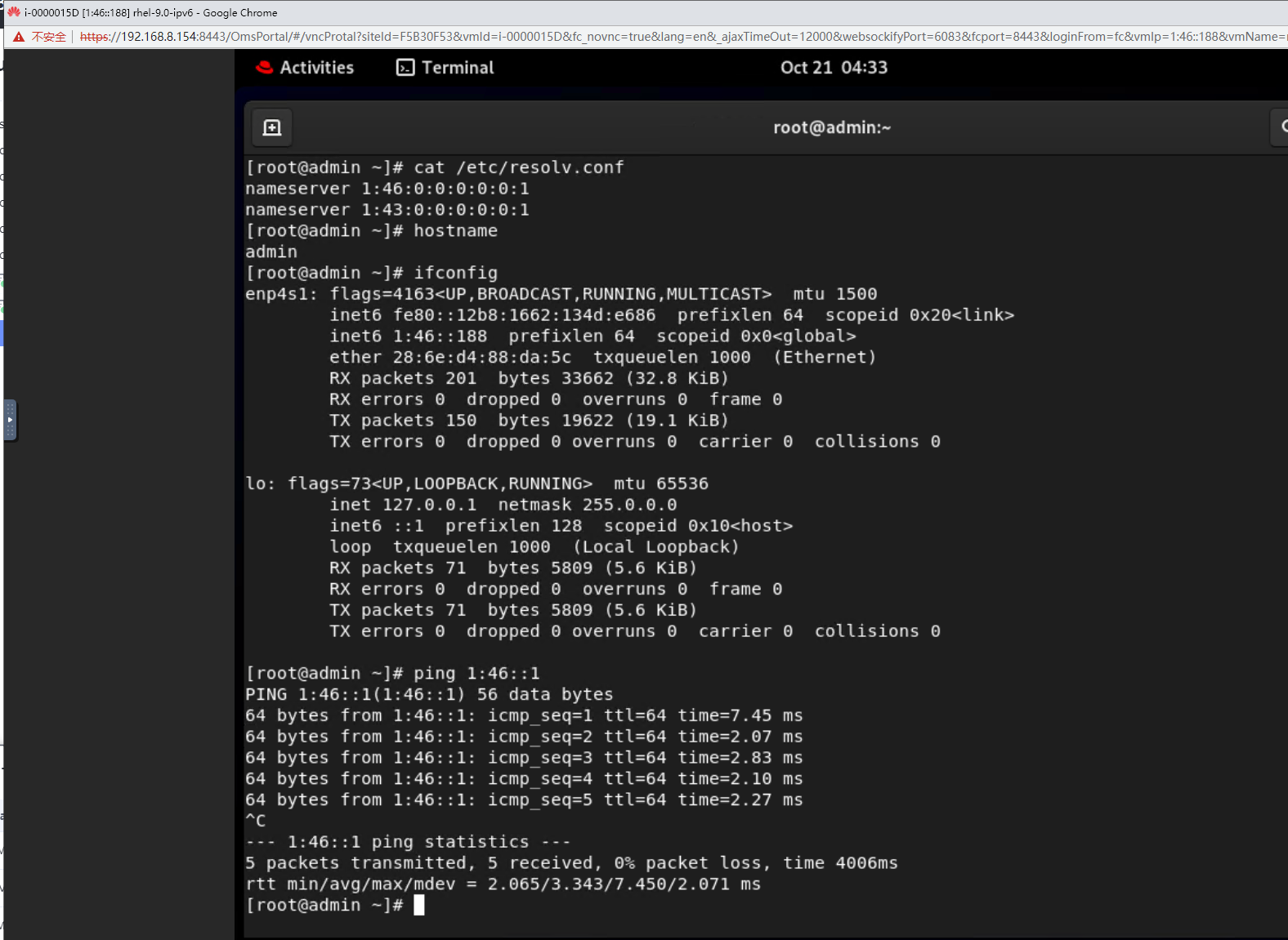 3. Forcibly reset the VM for three times. After each VM startup, check whether the customized information in steps 1 and 2 is lost or changed. (Expected result 3) 
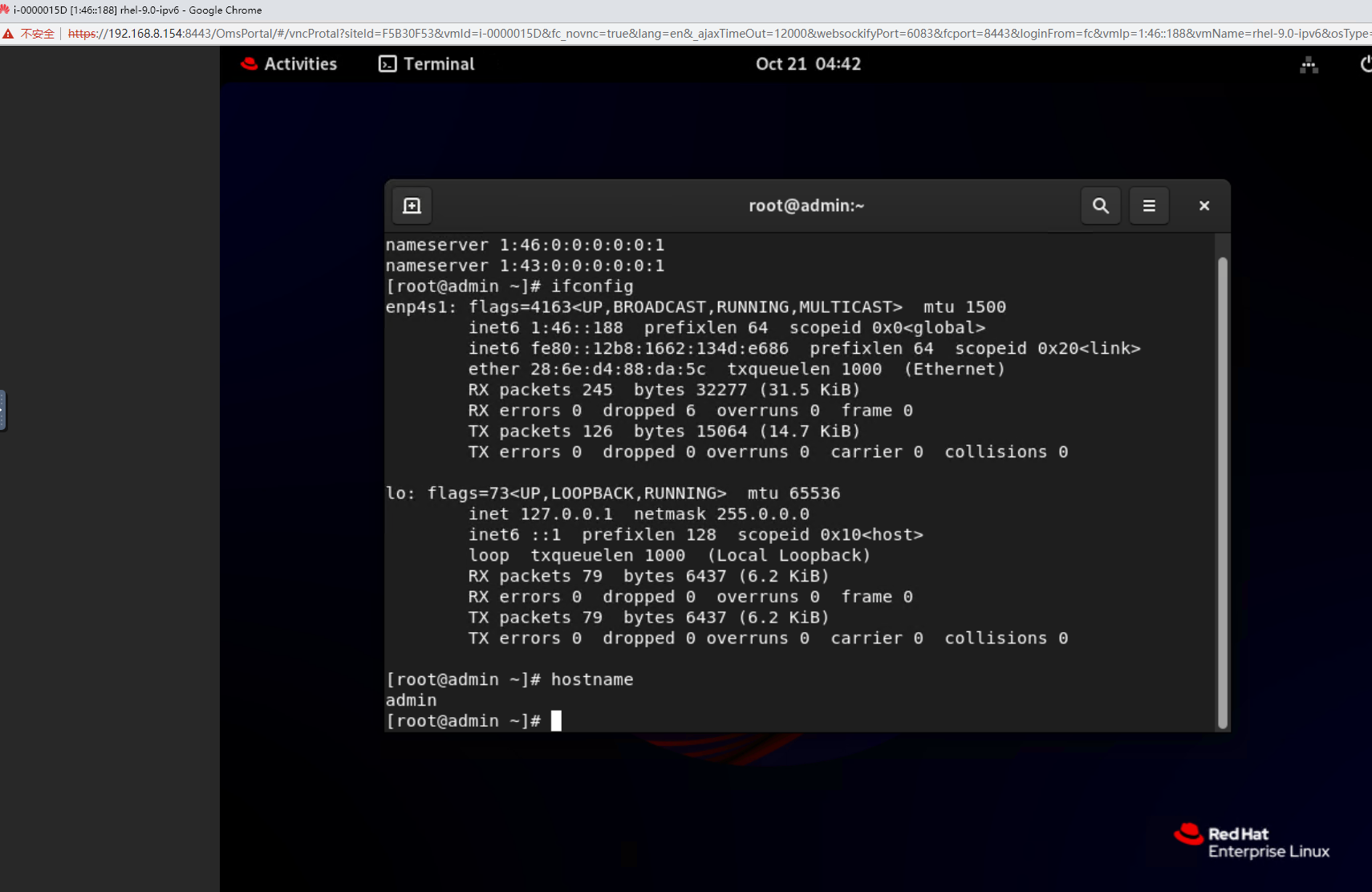

|
Conclusion |
|
Remarks |
3.15.3 Testing the Customized Configuration When the VRM Active/Standby Switchover Is Performed During IPv4 Address Customization
Objective | Verify that the customization configuration is normal when the VRM active/standby switchover is performed during IPv4 address customization. |
Networking | Networking diagram for verifying functions |
Prerequisites | 1. A guest OS VM to be tested has been created and VMTools corresponding to the SIA has been installed on the VM. 2. The VM is successfully converted to a template. Before converting the VM to a template, run the cat /etc/resolv.conf command to check whether the DNS address is automatically-obtained. If so, delete the automatically-obtained address from the resolv.conf file. (If the DNS address is not deleted, the accuracy of the automatically-obtained DNS address will be affected during template deployment.) 3. An IPv4 DHCP server has been configured on the network where the VM resides. 4. FusionCompute has been deployed in active/standby mode. |
Procedure | 1. Choose Resource Pool > VM Templates. Right-click the VM template and choose Deploy VM Using Template. In the displayed box, configure parameters in Basic Information and Configure VM. Then, in the Customize OS tab page, select Customize using the Customization Wizard, configure the computer name and administrator password, and set the network resource management type to workgroup and the network resource management name to workgroup name. 2. Customize NIC settings, set IP type to IPv4, configure the IP address and subnet mask, enable IPv4 route information, and configure the IPv4 route gateway, IPv4 destination network, IPv4 destination network mask, primary DNS server address (for example, 8.8.8.8), and secondary DNS server address (for example, 114.114.114.114). 3. Trigger an active/standby VRM switchover during VM customization. For details, see section « How Do I Perform Switchover Between Active and Standby VRM Nodes? » in FusionCompute Product Documentation. After the switchover is complete, expected result 1 is obtained. |
Expected Result | 1. After the VRM switchover, the customized IPv4 configuration is normal. |
Test Result | 1. Choose Resource Pool > VM Templates. Right-click the VM template and choose Deploy VM Using Template. In the displayed box, configure parameters in Basic Information and Configure VM. Then, in the Customize OS tab page, select Customize using the Customization Wizard, configure the computer name and administrator password, and set the network resource management type to workgroup and the network resource management name to workgroup name. 
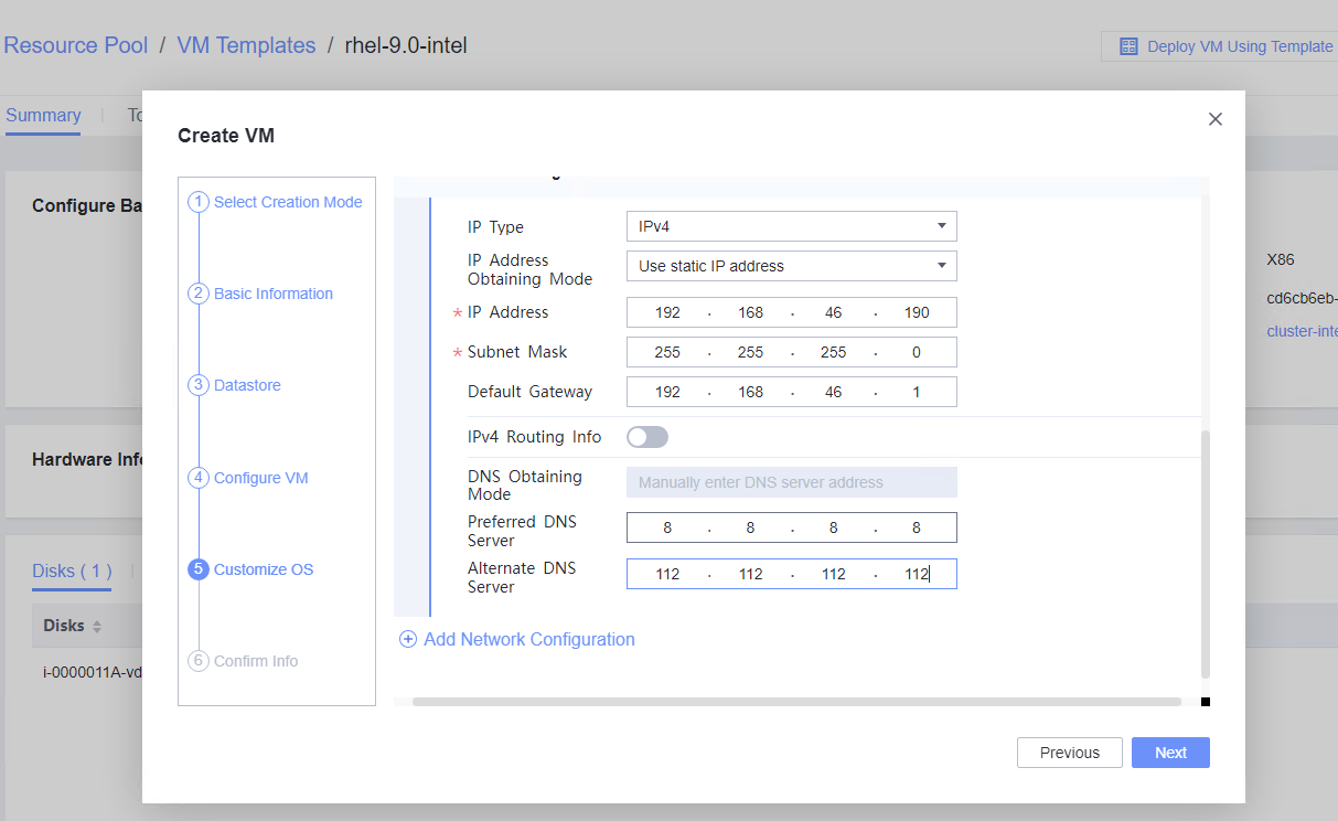
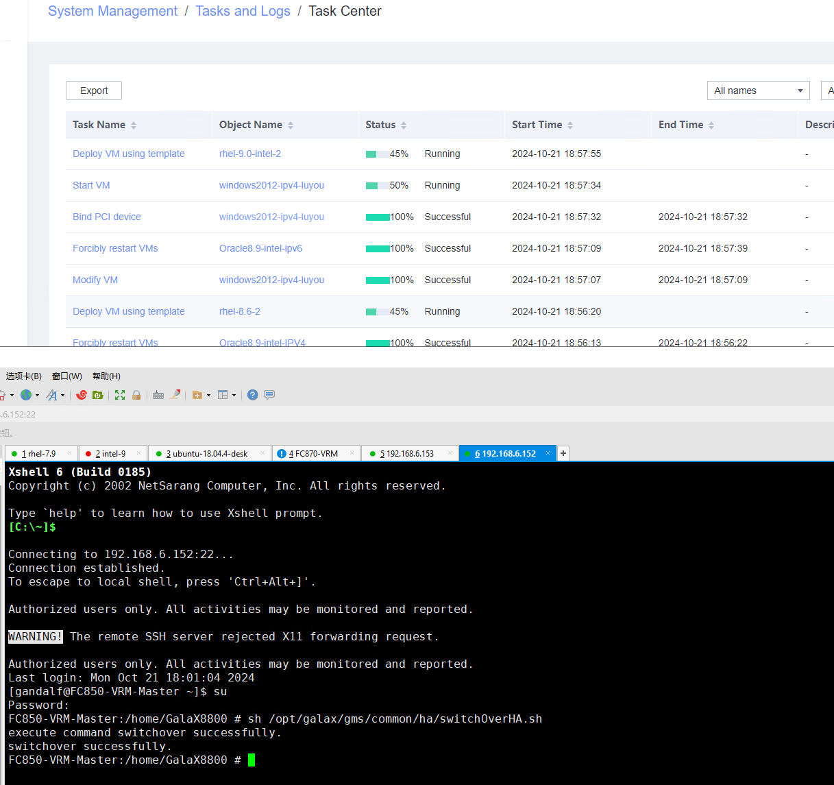
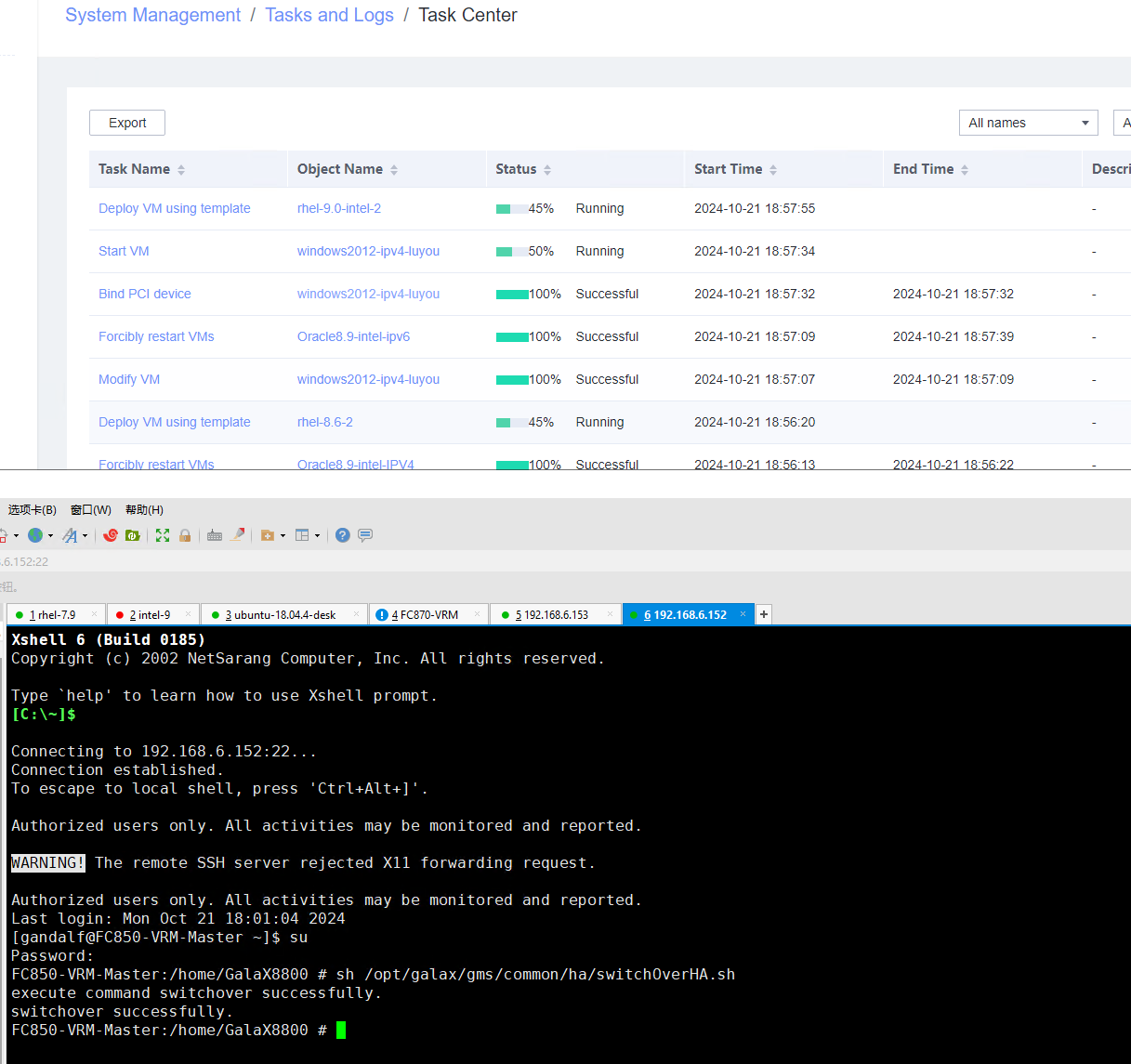

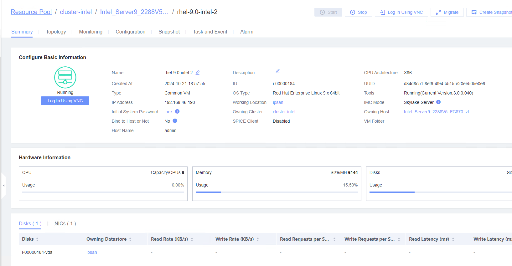 2. Customize NIC settings, set IP type to IPv4, configure the IP address and subnet mask, enable IPv4 route information, and configure the IPv4 route gateway, IPv4 destination network, IPv4 destination network mask, primary DNS server address (for example, 8.8.8.8), and secondary DNS server address (for example, 114.114.114.114). 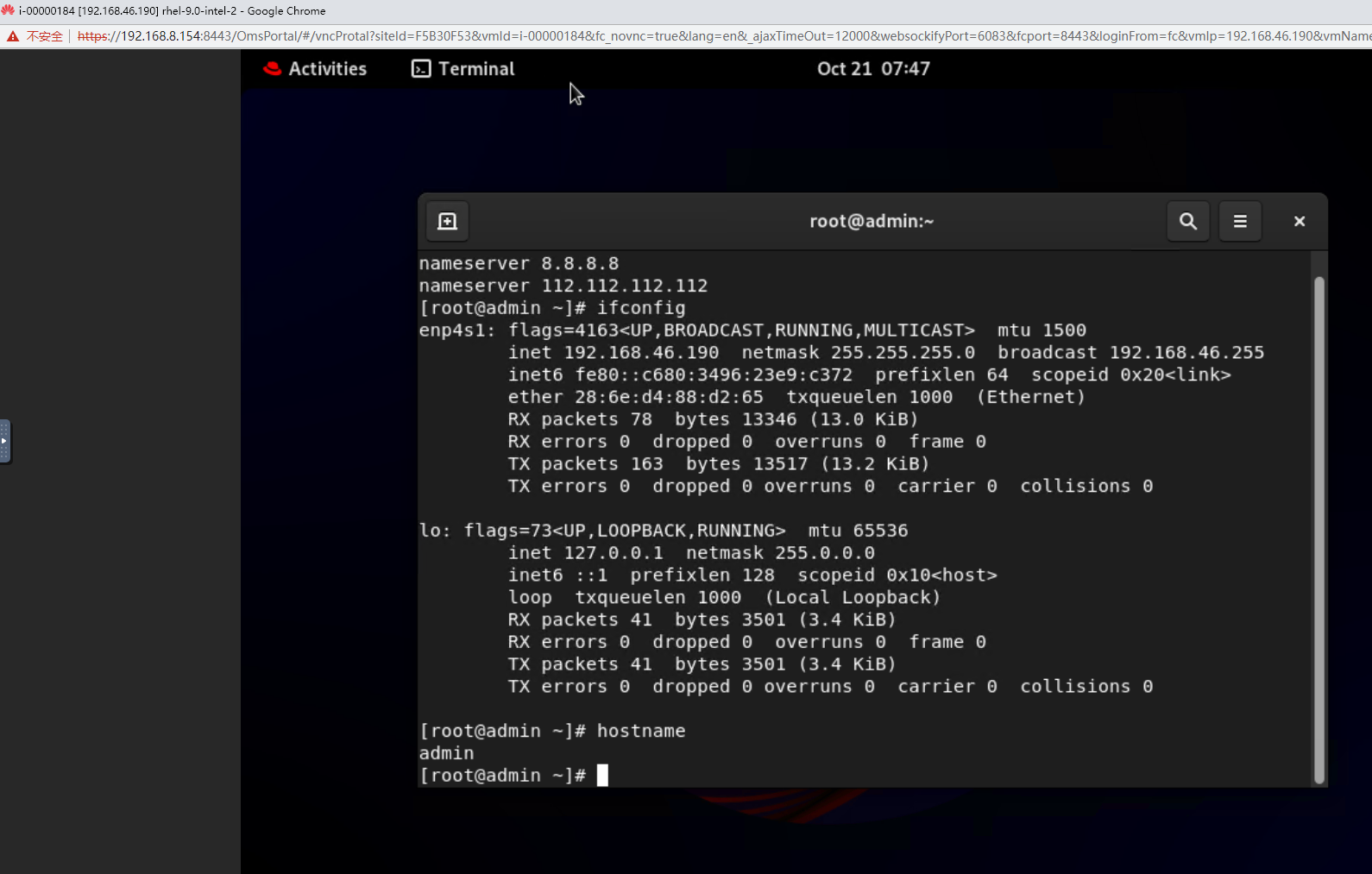 3. Trigger an active/standby VRM switchover during VM customization. For details, see section « How Do I Perform Switchover Between Active and Standby VRM Nodes? » in FusionCompute Product Documentation. After the switchover is complete, expected result 1 is obtained. 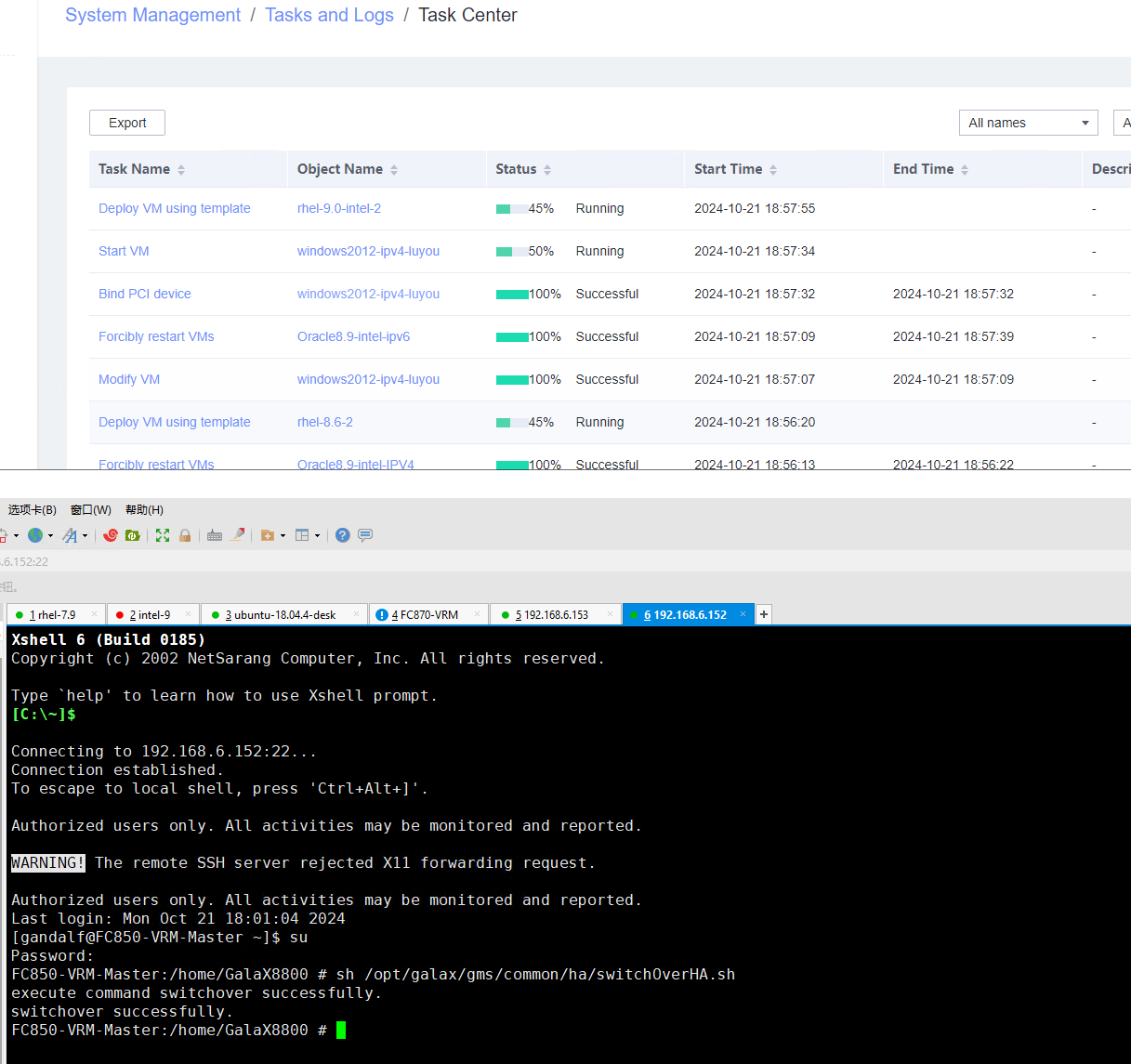
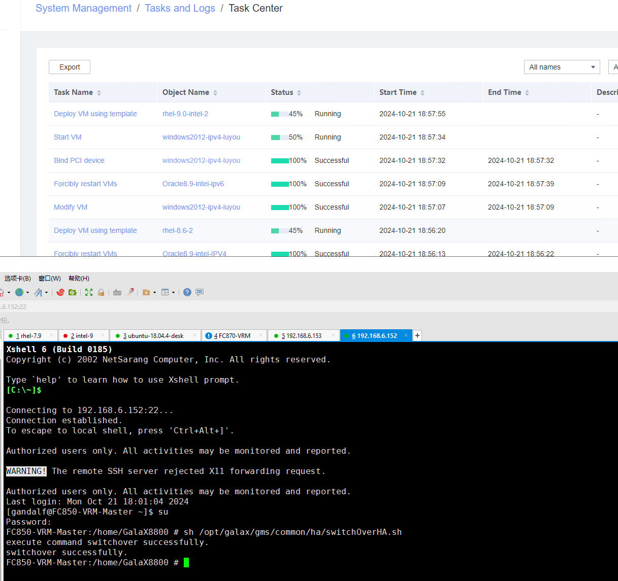
|
Conclusion |
|
Remarks |
3.15.4 Verifying that IPv4 Addresses Can Be Customized for the Three VMs at the Same Time
Objective | Verify that IPv4 addresses can be customized for the three VMs at the same time. |
Networking | Networking diagram for verifying functions |
Prerequisites | 1. A guest OS VM to be tested has been created and VMTools corresponding to the SIA has been installed on the VM. 2. The VM has been converted to a template. Before converting the VM to a template, run the cat /etc/resolv.conf command to check whether the DNS address is automatically obtained. If so, delete the automatically-obtained address from the resolv.conf file. (If the DNS address is not deleted, the accuracy of the automatically-obtained DNS address will be affected during template deployment.) 3. An IPv4 DHCP server has been configured on the network where the VM resides. 4. FusionCompute has been deployed in active/standby mode. |
Procedure | 1. Deploy VM 1 using a template: Choose Resource Pool > VM Templates. Right-click the VM template and choose Deploy VM Using Template. In the displayed box, configure parameters in Basic Information and Configure VM. Then, in the Customize OS tab page, select Customize using the Customization Wizard, configure the computer name and administrator password, and set the network resource management type to workgroup and the network resource management name to workgroup name. Customize NIC settings, set IP Type to IPv4, configure the IP address and subnet mask, enable IPv4 route information, and configure the IPv4 route gateway, IPv4 destination network, IPv4 destination network mask, primary DNS server address (for example, 8.8.8.8), and secondary DNS server address (for example, 114.114.114.114). (Expected result 1) 2. Use the template in step 1 to deploy VM 2. The configuration is the same as that in step 1. (Expected result 1) 3. Use the template in step 1 to deploy VM 3. The configuration is the same as that in step 1. (Expected result 1) |
Expected Result | 1. The customized IPv4 configuration is normal. |
Test Result | 1. Deploy VM 1 using a template: Choose Resource Pool > VM Templates. Right-click the VM template and choose Deploy VM Using Template. In the displayed box, configure parameters in Basic Information and Configure VM. Then, in the Customize OS tab page, select Customize using the Customization Wizard, configure the computer name and administrator password, and set the network resource management type to workgroup and the network resource management name to workgroup name. Customize NIC settings, set IP Type to IPv4, configure the IP address and subnet mask, enable IPv4 route information, and configure the IPv4 route gateway, IPv4 destination network, IPv4 destination network mask, primary DNS server address (for example, 8.8.8.8), and secondary DNS server address (for example, 114.114.114.114). (Expected result 1) 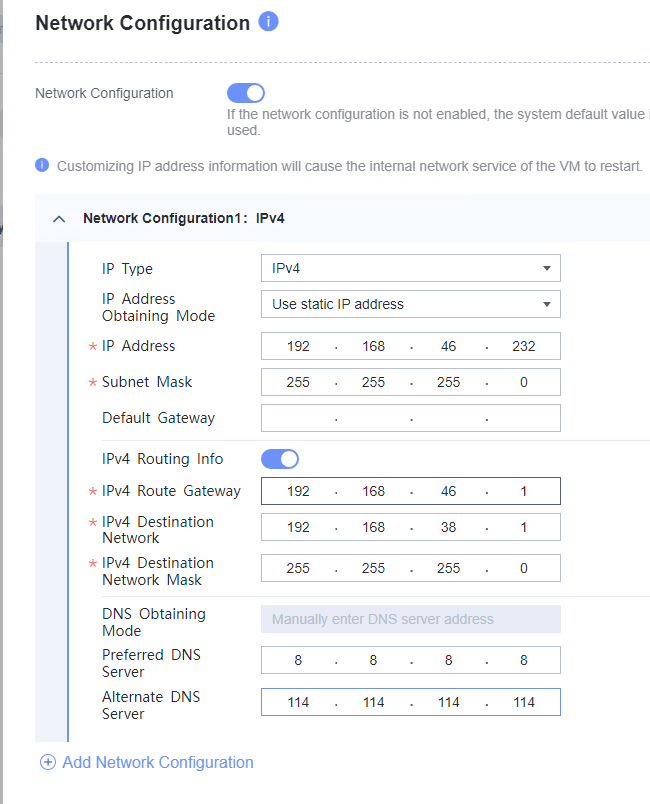
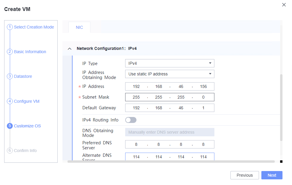
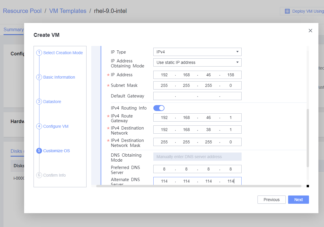 2. Use the template in step 1 to deploy VM 2. The configuration is the same as that in step 1. (Expected result 1) 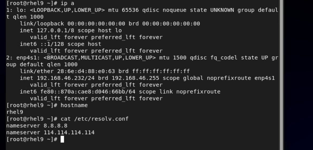
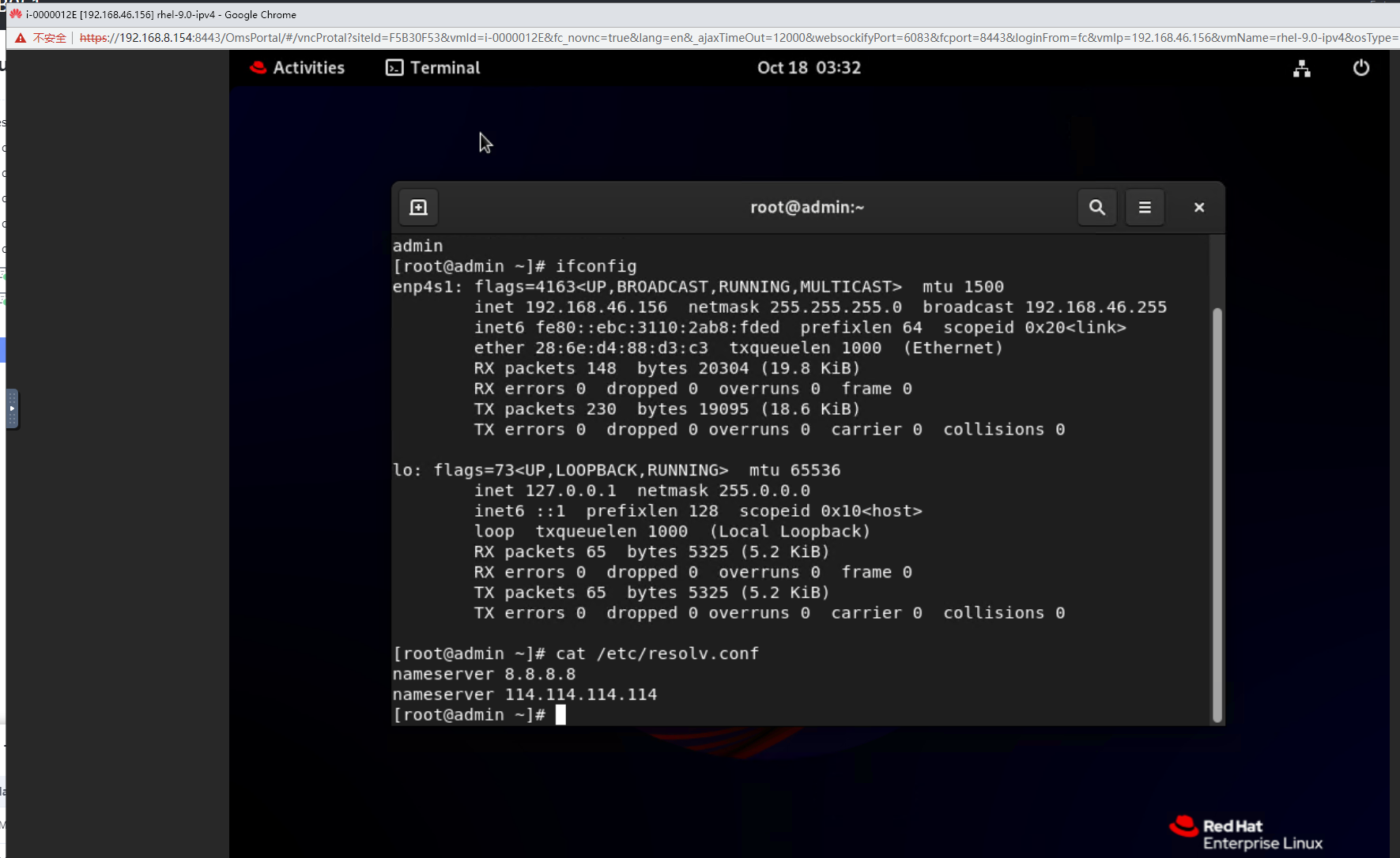 3. Use the template in step 1 to deploy VM 3. The configuration is the same as that in step 1. (Expected result 1) 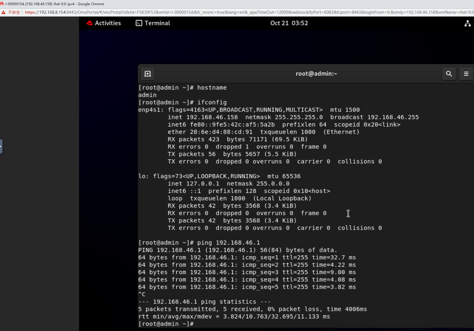
|
Conclusion |
|
Remarks |
3.15.5 Testing the Reliability of Restarting the VRM Service
Objective | Verify that restarting the VRM service is reliable. |
Networking | Networking diagram for verifying functions |
Prerequisites | 1. The VMTools package corresponding to the SIA has been prepared. |
Procedure | 1. After the SIA is upgraded in the FusionCompute environment, restart the VRM services (service vrmd restart and service portal restart) for three times. (Expected result 1) |
Expected Result | 1. Each time after the VRM is reset, the login to the FusionCompute page is normal, and the login using VNC is normal. |
Test Result | 1. After the SIA is upgraded in the FusionCompute environment, restart the VRM services (service vrmd restart and service portal restart) for three times. (Expected result
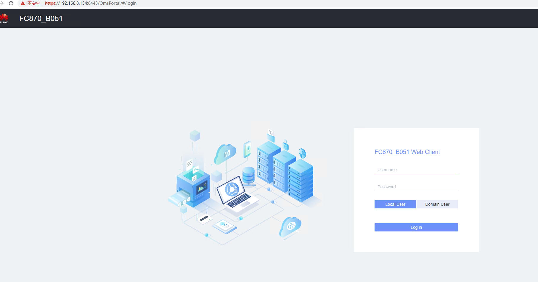
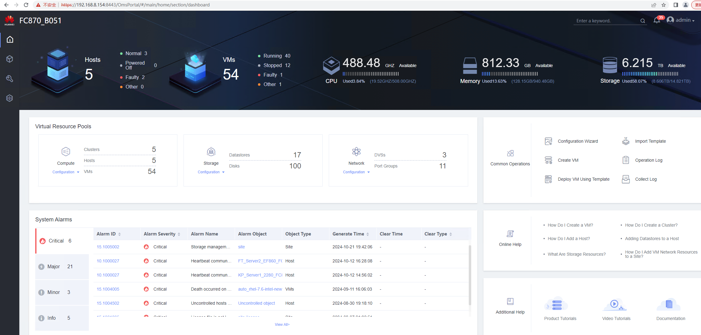
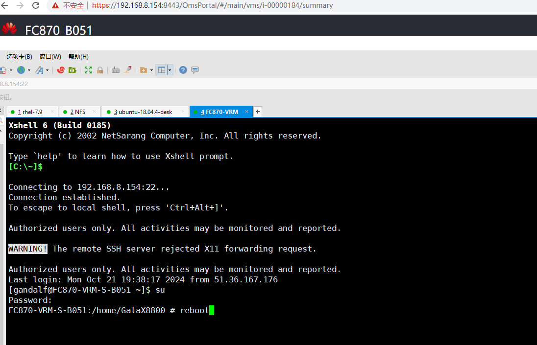
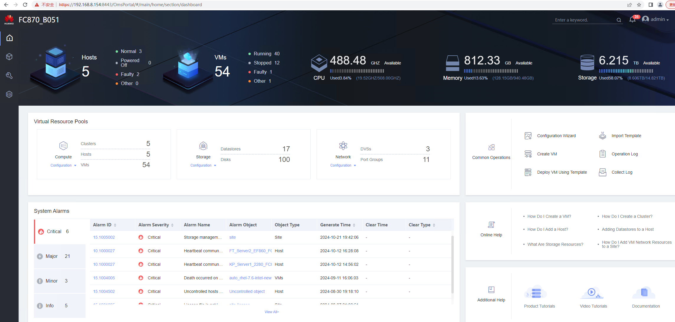

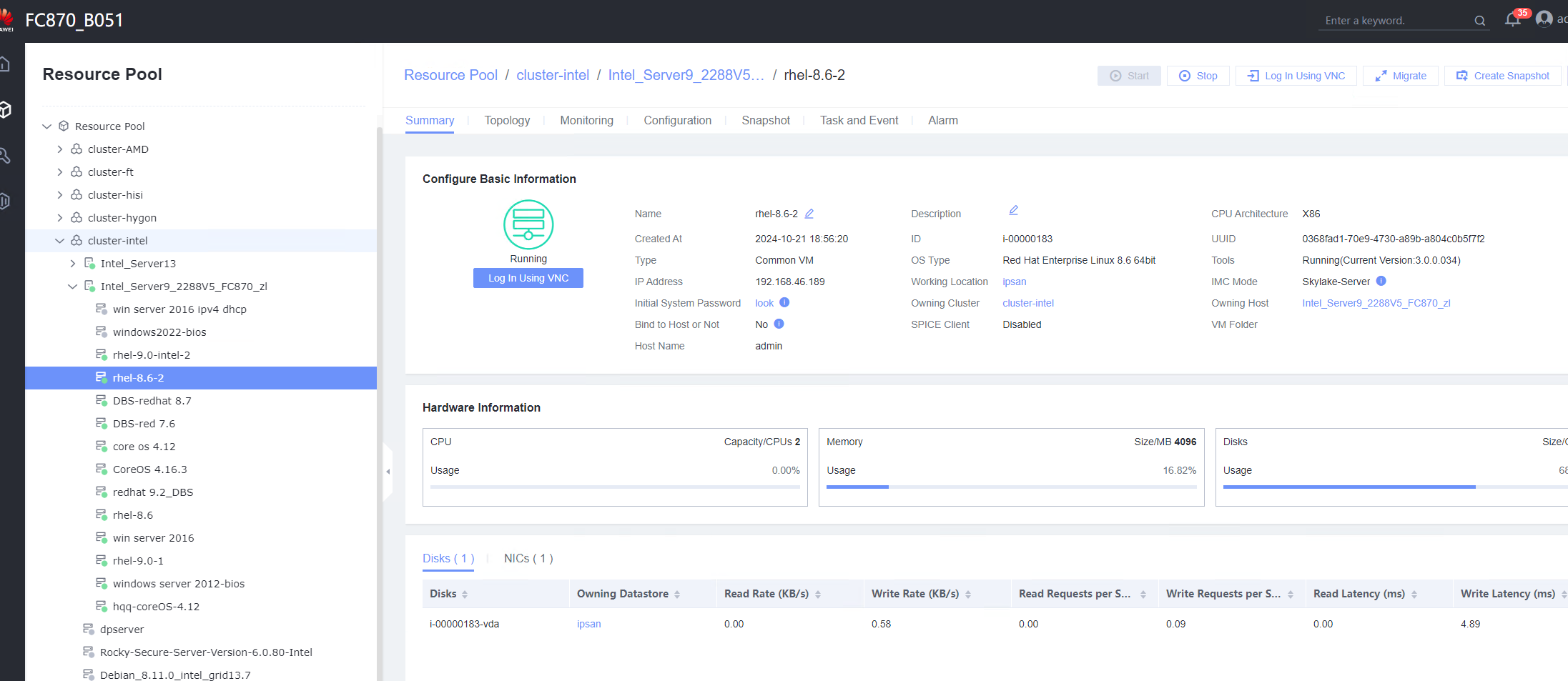
|
Conclusion |
|
Remarks |
3.15.6 Testing the Reliability Upon a Host Power Failure
Objective | Verify the reliability upon a host power failure. |
Networking | Networking diagram for verifying functions |
Prerequisites | The guest OS VMs to be tested have been created and VMTools corresponding to the SIA has been installed on the VMs. |
Procedure | 1. Deploy VMs whose IPv4 and IPv6 addresses are customized. Set the computer name, administrator password, network resource management type to workgroup and the network resource management name to the workgroup name. Customize the NIC settings, set the IP address type to IPv4 and IPv6, enter the IP address and subnet mask, enable IPv4 route information, enter the IP route gateway, IP destination network, IP destination network mask, primary DNS server address, and secondary DNS server address. 2. The VMs to be tested are running properly. Log in to the iBMC page of the host, power off and then power on the host, and repeat this step for three times. 3. Each time the host is powered off and then powered on, check the customized IPv4 and IPv6 information of the VMs. (Expected result 1) 4. Each time the host is powered off and then powered on, check the network connectivity. (Expected result 2) 5. Each time the host is powered off and then powered on, check the VM monitoring information. (Expected result 3) |
Expected Result | 1. Customized IPv4 and IPv6 information is not lost. 2. The login to the host using SSH (Linux OS) or remote desktop (Windows) is successful. 3. The monitoring information about the CPU usage, memory usage, disk usage, disk I/O, and network throughput is displayed properly. |
Test Result | 1. Deploy VMs whose IPv4 and IPv6 addresses are customized. Set the computer name, administrator password, network resource management type to workgroup and the network resource management name to the workgroup name. Customize the NIC settings, set the IP address type to IPv4 and IPv6, enter the IP address and subnet mask, enable IPv4 route information, enter the IP route gateway, IP destination network, IP destination network mask, primary DNS server address, and secondary DNS server address. 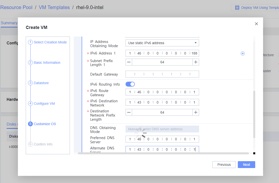  2. The VMs to be tested are running properly. Log in to the iBMC page of the host, power off and then power on the host, and repeat this step for three times. 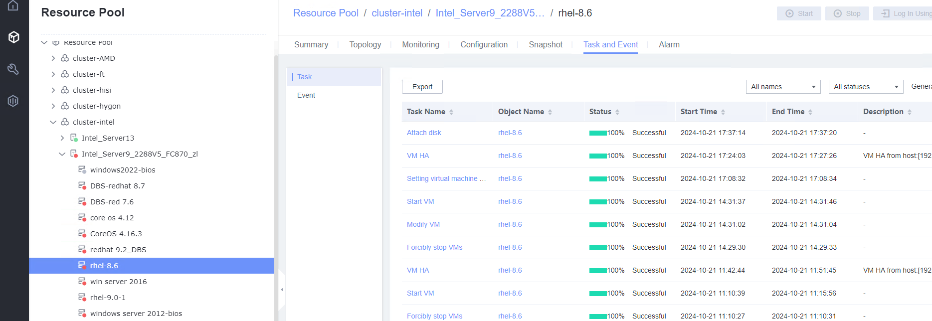 Second time: 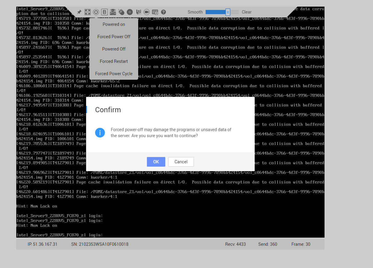 Third time: 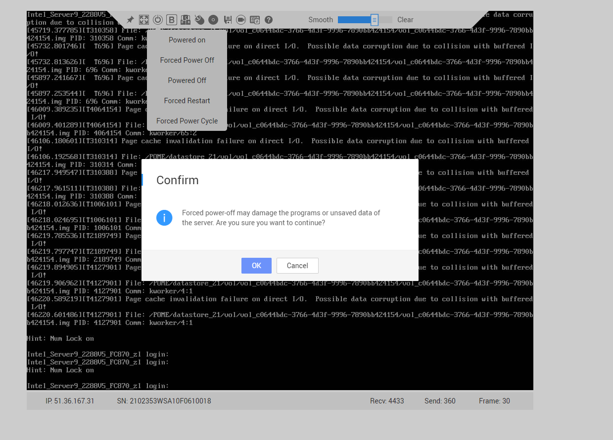 3. Each time the host is powered off and then powered on, check the customized IPv4 and IPv6 information of the VMs. (Expected result 1)

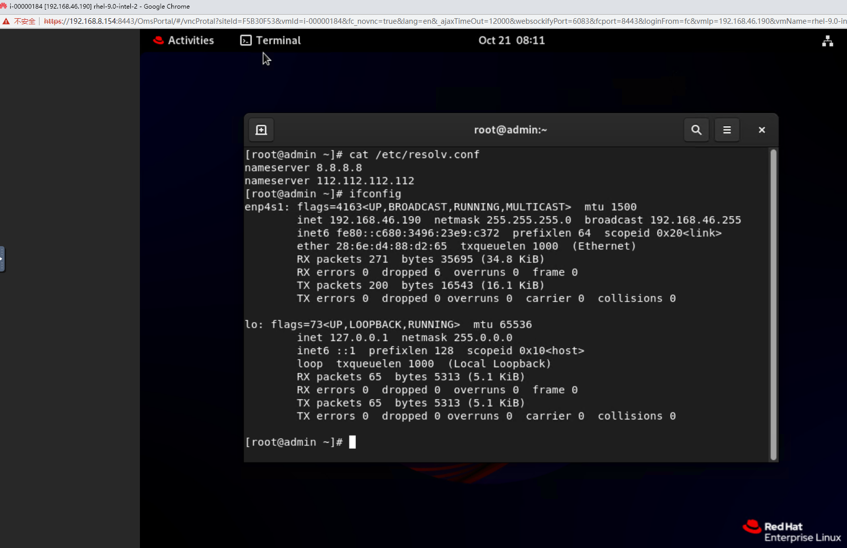 Third time: 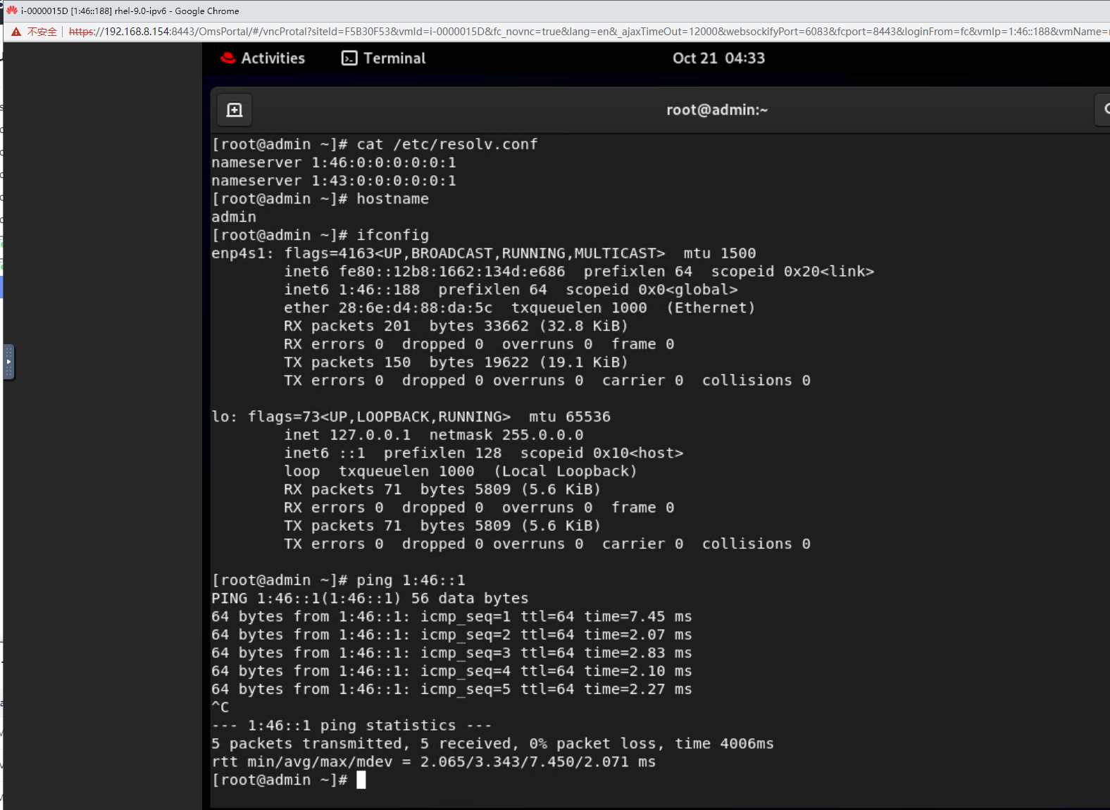 4. Each time the host is powered off and then powered on, check the network connectivity. (Expected result 2) 
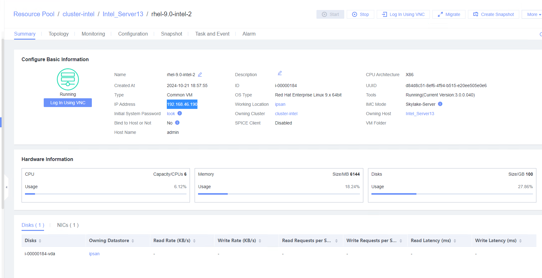
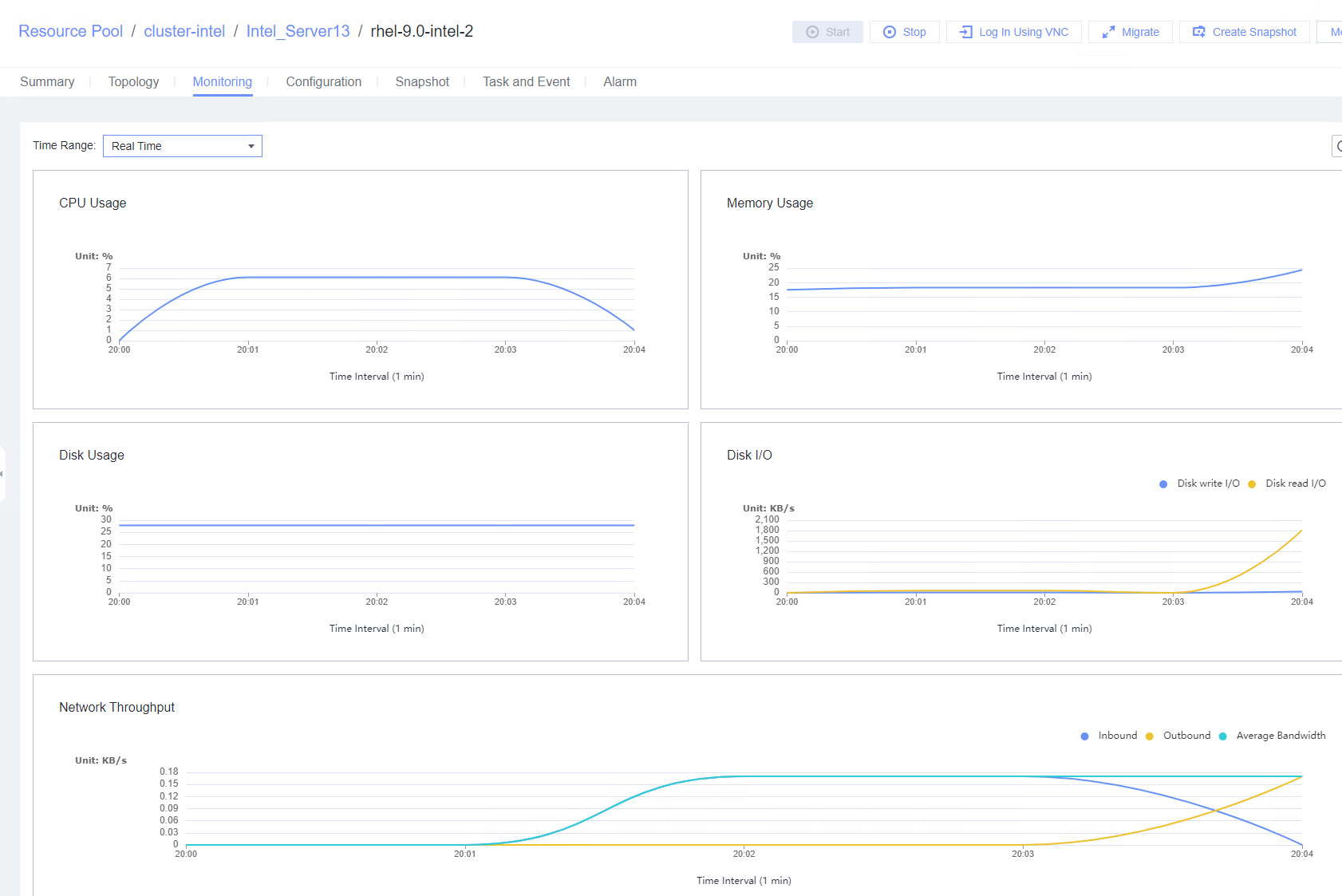
|
Conclusion |
|
Remarks |
4. Verification Result
4.1 Test Result
Table 4-1 The following table lists the result of each test case.
Category | Case No. | Case Name | Test Result |
|---|---|---|---|
Guest OS Installation | 3.1.1 | Installing a Guest OS Image in BIOS Mode | Pass |
3.1.2 | Installing a Guest OS Image in UEFI Mode | Pass | |
VMTools Installation, Upgrade, and Uninstallation | 3.2.1 | Installing VMTools | Pass |
3.2.2 | Upgrading and Uninstalling VMTools | Pass | |
VM Lifecycle Management | 3.3.1 | Importing or Exporting a VM Template, Converting a VM to a Template, and Cloning a VM | Pass |
3.3.2 | Testing the VM Power Supply | Pass | |
3.3.3 | Testing the VM Live Migration Function | Pass | |
3.3.4 | Deleting a VM | Pass | |
Disk Hot Swap | 3.4.1 | Attaching a Disk Whose Bus Type Is SCSI to or Detaching It from a Running VM | Pass |
3.4.2 | Attaching a Disk Whose Bus Type Is VIRTIO to or Detaching It from a Running VM | Pass | |
VM NIC Operations | 3.5.1 | Adding a NIC to or Deleting It from a Running VM | Pass |
3.5.2 | Testing the PCI Passthrough NIC of a VM | Pass | |
3.5.3 | Testing the VM NIC in SR-IOV Passthrough Mode | Pass | |
3.5.4 | Testing the Network Configuration of the VM NICs | Pass | |
Adding CPU and Memory to a VM | 3.6.1 | Adjusting the CPU and Memory Specifications of a Running VM | Pass |
3.6.2 | Configuring the CPU and Memory and Restarting a VM for the Configuration to Take Effect | Pass | |
VM Clock Policy | 3.7.1 | Testing the VM Clock Synchronization | Pass |
3.7.2 | Testing the Free Clock Function of the VM | Pass | |
Maintainability Function | 3.8.1 | Testing the Serial Port Log Record Function on the Host | Pass |
OS Customization | 3.9.1 | Customizing the Computer Name, Password, and NIC (Automatically Obtaining an IPv4 Address) | Pass |
3.9.2 | Customizing the Computer Name, Password, and NIC (with the Specified IPv4 Address and Default Gateway) | Pass | |
3.9.3 | Customizing the Computer Name, Password, and NIC (with Specified IPv4 Address and IPv4 Route Information) | Pass | |
3.9.4 | Customizing the Computer Name, Password, and NIC (Automatically Obtaining an IPv6 Address Through DHCP) | Pass | |
3.9.5 | Customizing the Computer Name, Password, and NIC (Automatically Obtaining an IPv6 Address by Router Advertisement) | Pass | |
3.9.6 | Customizing the Computer Name, Password, and NIC (with Specified IPv6 Address) | Pass | |
3.9.7 | Generating an Initial Password When Customization Is Not Used | Pass | |
Snapshot | 3.10.1 | Creating a Storage Snapshot | Pass |
3.10.2 | Creating a Memory Snapshot | Pass | |
3.10.3 | Creating a Consistency Snapshot | Pass | |
USB Passthrough | 3.11.1 | Verifying the USB Passthrough Function of a VM | Pass |
SSD | 3.12.1 | Binding or Unbinding an SSD from a VM | Pass |
GPU | 3.13.1 | Testing Basic GPU Functions of the Guest OS Passthrough GPU Device in the Linux System | Pass |
3.13.2 | Testing the Basic vGPU Functions of the Guest OS vGPU Device in the Linux System | Pass | |
3.13.3 | Testing Basic GPU Functions of the Guest OS Passthrough GPU Device in the Windows System | Pass | |
3.13.4 | Testing the Basic vGPU Functions of the Guest OS vGPU Device in the Windows System | Pass | |
Other Value-added Functions of the Guest OS | 3.14.1 | Testing NUMA Topology Adjustment | Pass |
3.14.2 | Testing the I/O Suspension Function | Pass | |
3.14.3 | Testing the CPU Cache Consistency Between the VM and the Host | Pass | |
Guest OS Basic Reliability Test | 3.15.1 | Testing the Customized IPv4 Configuration After the VM Is Repeatedly Reset | Pass |
3.15.2 | Testing the Customized IPv6 Configuration After the VM Is Repeatedly Reset | Pass | |
3.15.3 | Testing the Customized Configuration When the VRM Active/Standby Switchover Is Performed During IPv4 Address Customization | Pass | |
3.15.4 | Verifying that IPv4 Addresses Can Be Customized for the Three VMs at the Same Time | Pass | |
3.15.5 | Testing the Reliability of Restarting the VRM Service | Pass | |
3.15.6 | Testing the Reliability Upon a Host Power Failure | Pass |
4.2 Conclusion
According to the test result, FusionCompute is compatible with guest OS (Red Hat Enterprise Linux 9.0).

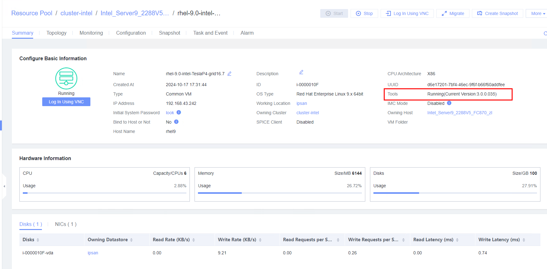 2. Upload the target vmtools-xxx.tar.bz2 installation package to the root directory of the VM, run the tar -xjvf vmtools-xxx.tar.bz2 command to decompress the package, go to the vmtools directory, and run the ./install upgrade command to upgrade VMTools to the target version. (Expected result 2)
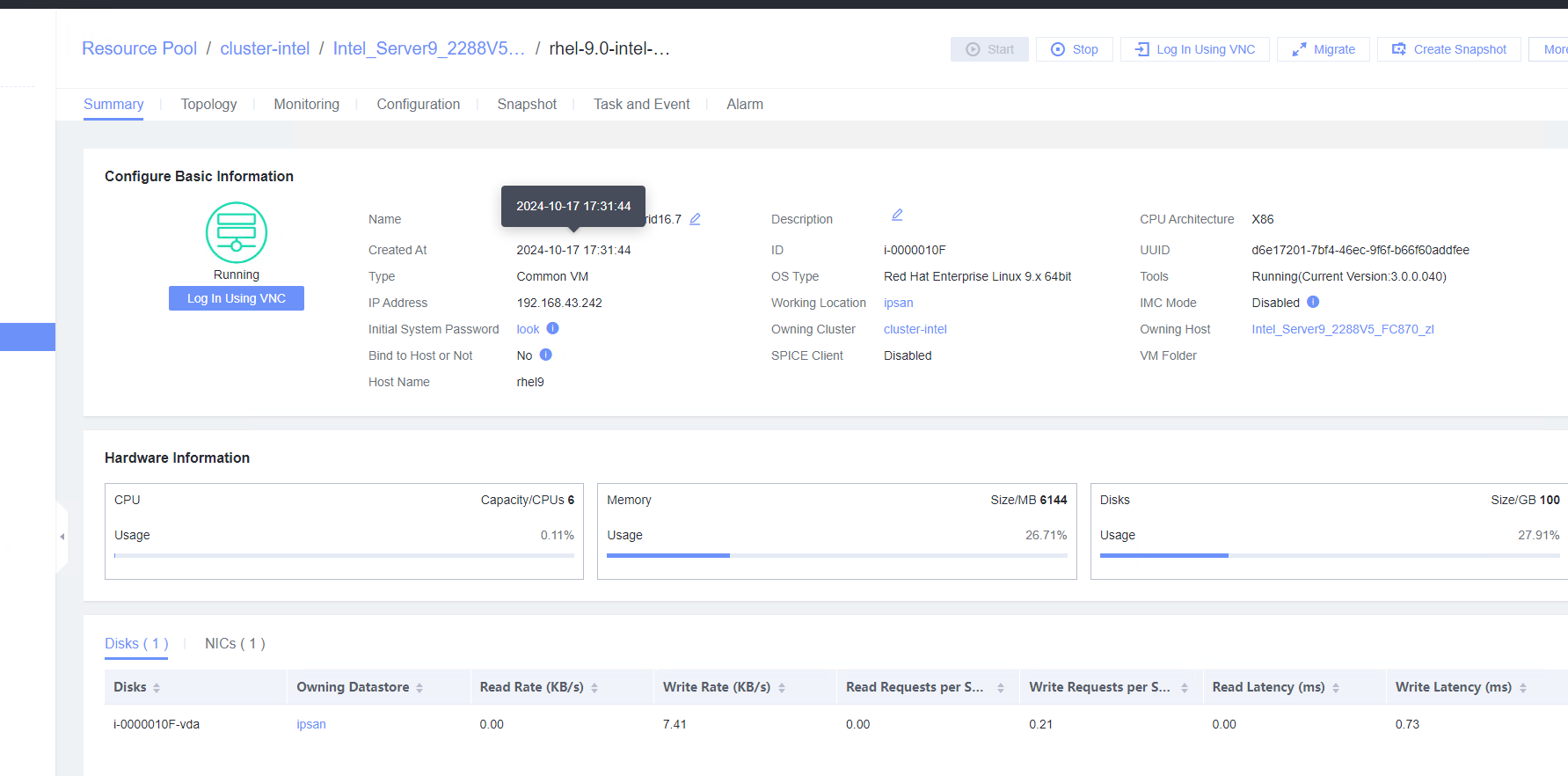 3. View the VM information on the Monitoring tab page. (Expected result 3)
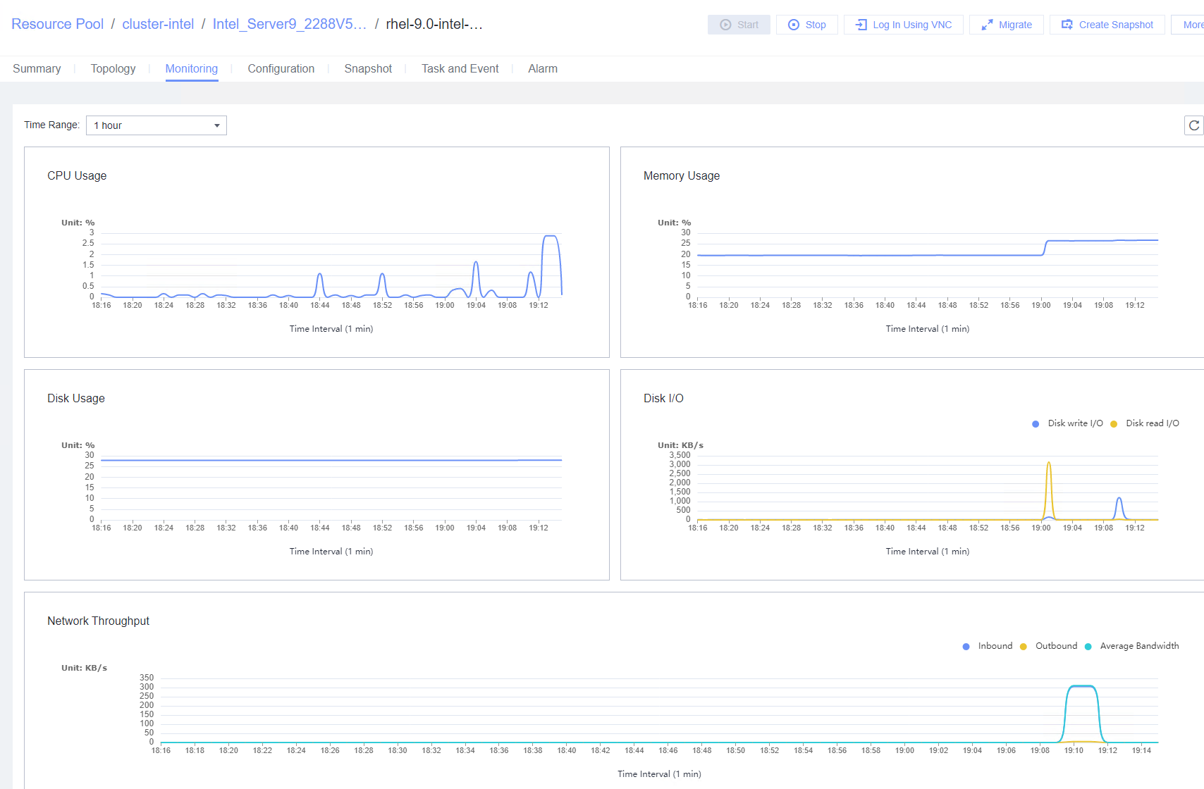
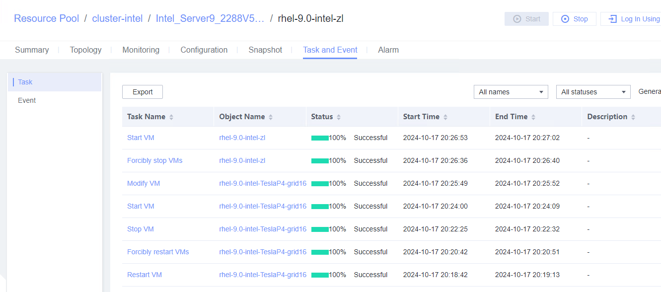 2. Log in to the VM using VNC. (Expected result 2)
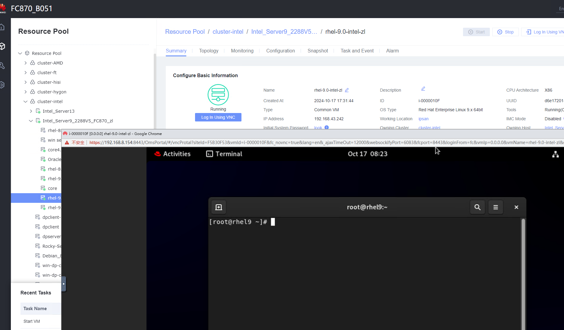 3. After the VM is started, open a test file, enter any character string, right-click the VM without exiting the editor, and choose Power > Hibernate. (Expected result 3)

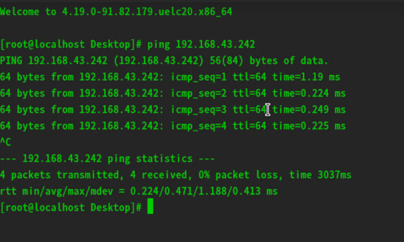


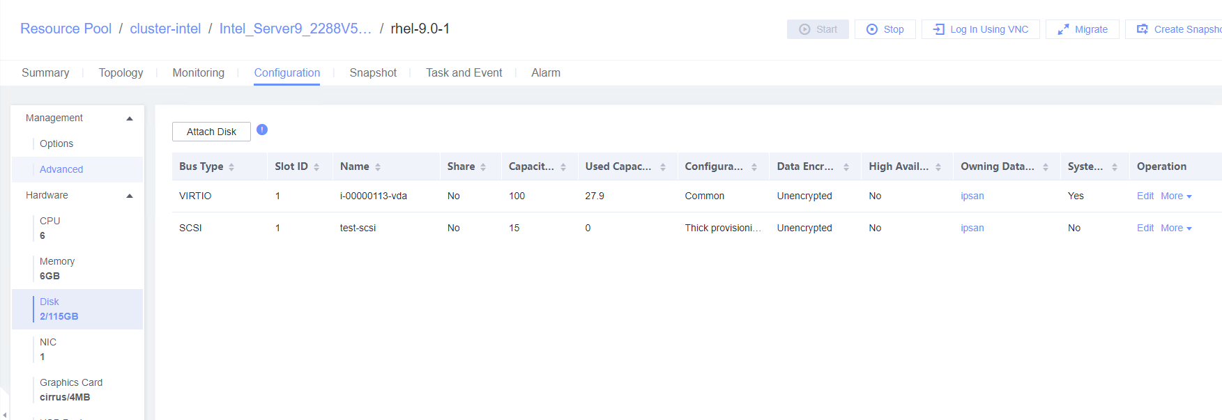
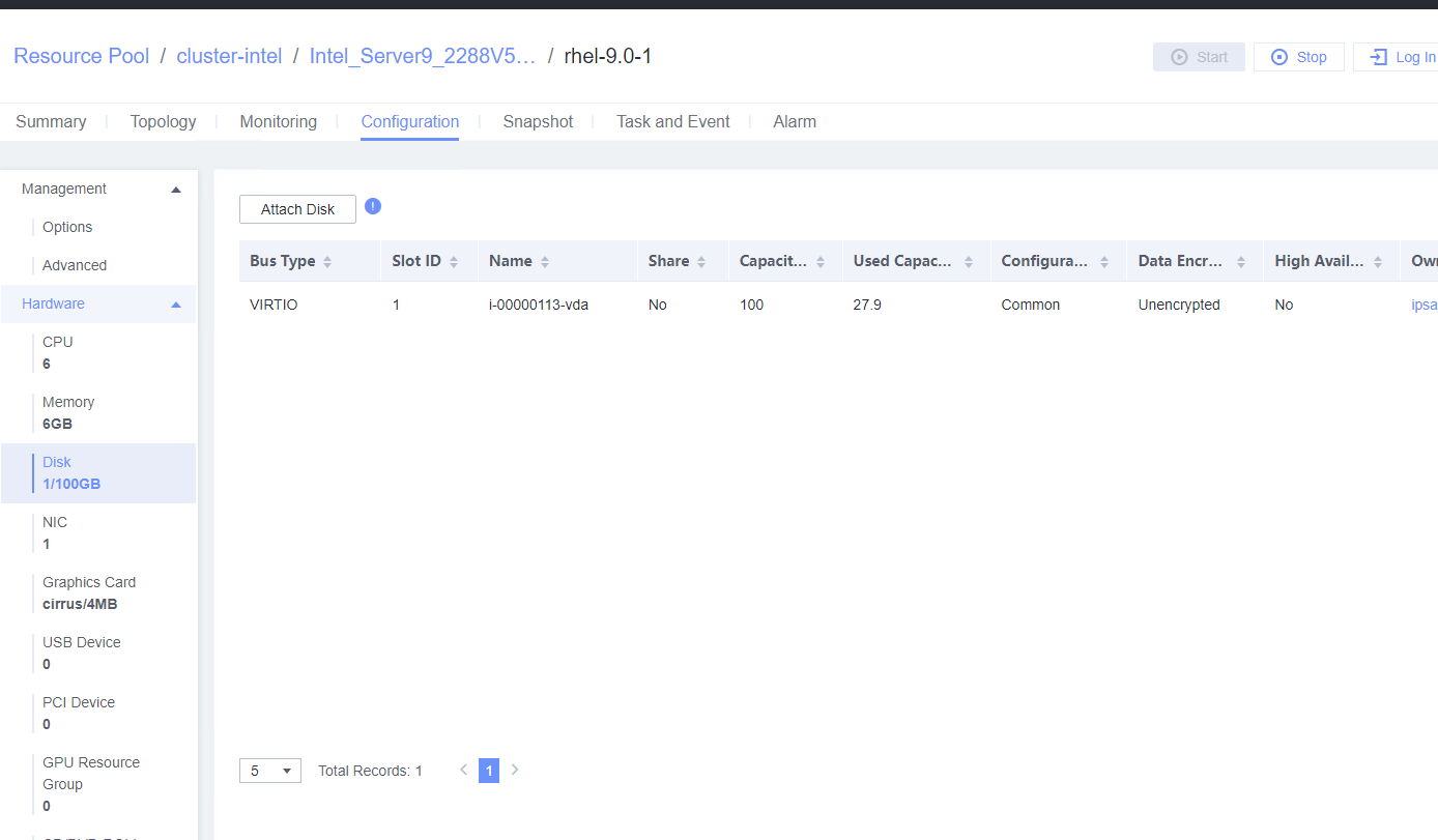
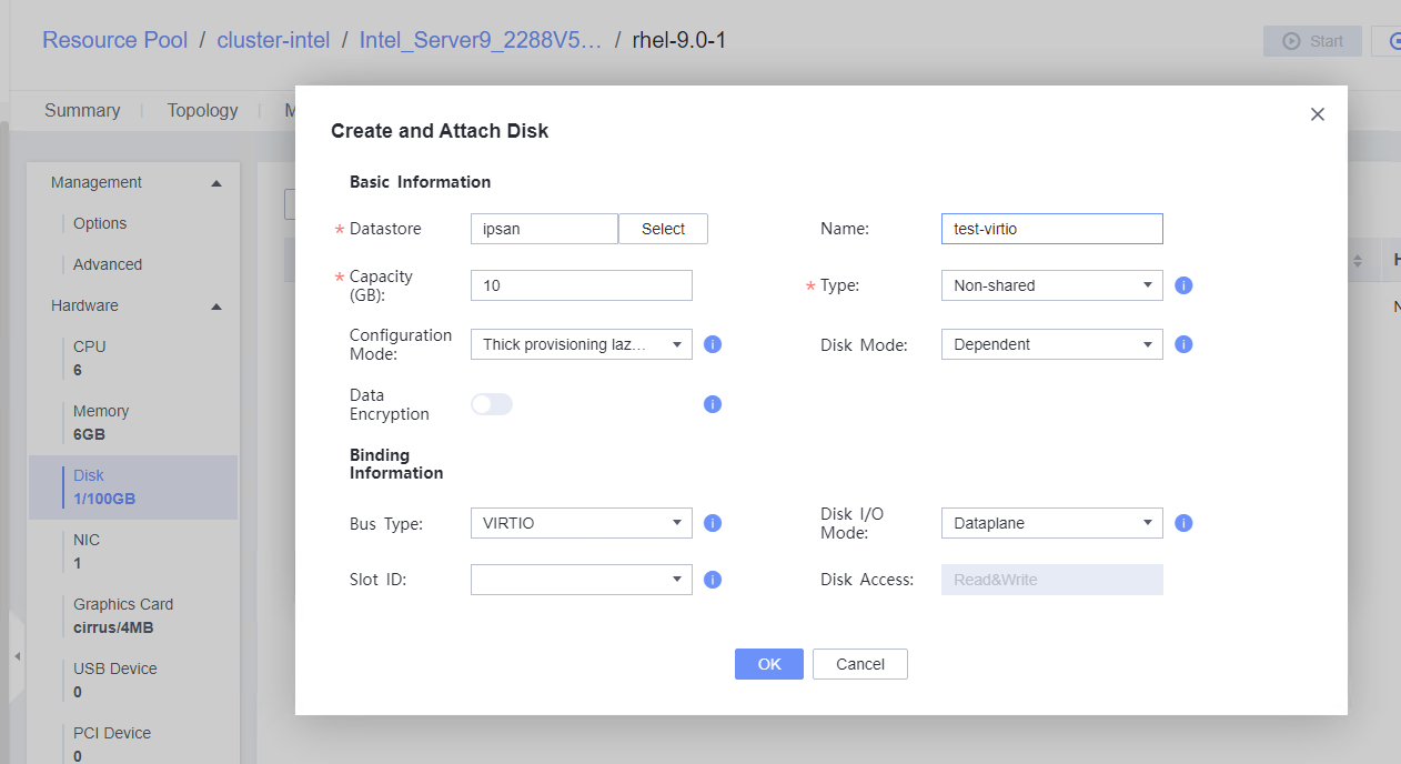 2. Select the VM and choose Configuration > Disk to view the disk information. (Expected result 2)
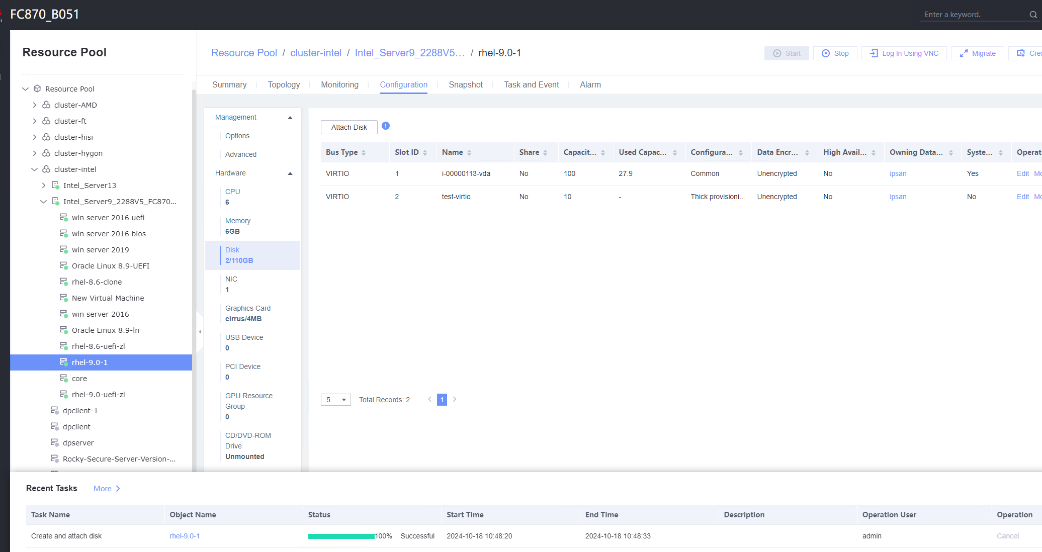 3. Log in to the VM, run the lsblk command to query the newly added disk, format the disk, and mount the disk to the specified directory. Then, create, modify, and delete files on the new disk. (Expected result 3)
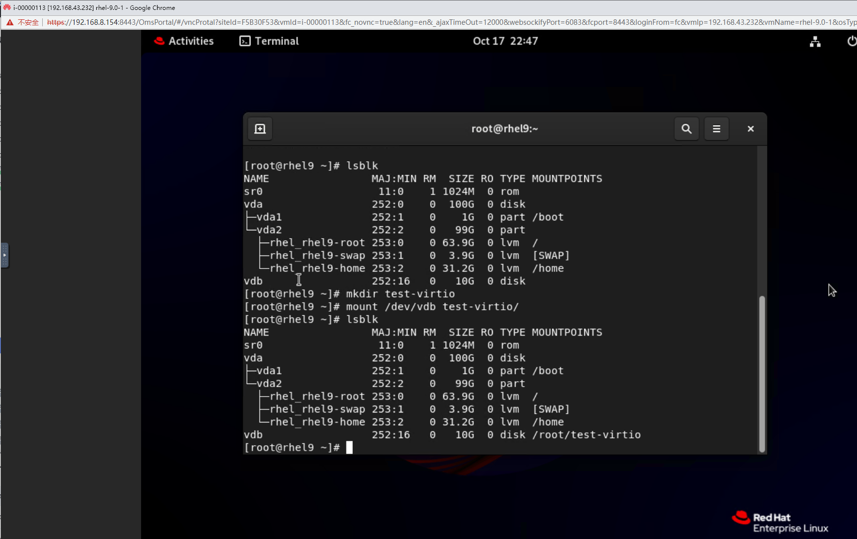

 4. Select the VM, which is in the running state, choose Configuration > Hardware > Disk, select the disk created in step 1, and choose More > Detach. Note: For some OSs, you may need to shut down the VM before detaching the disk. (Expected result 4)
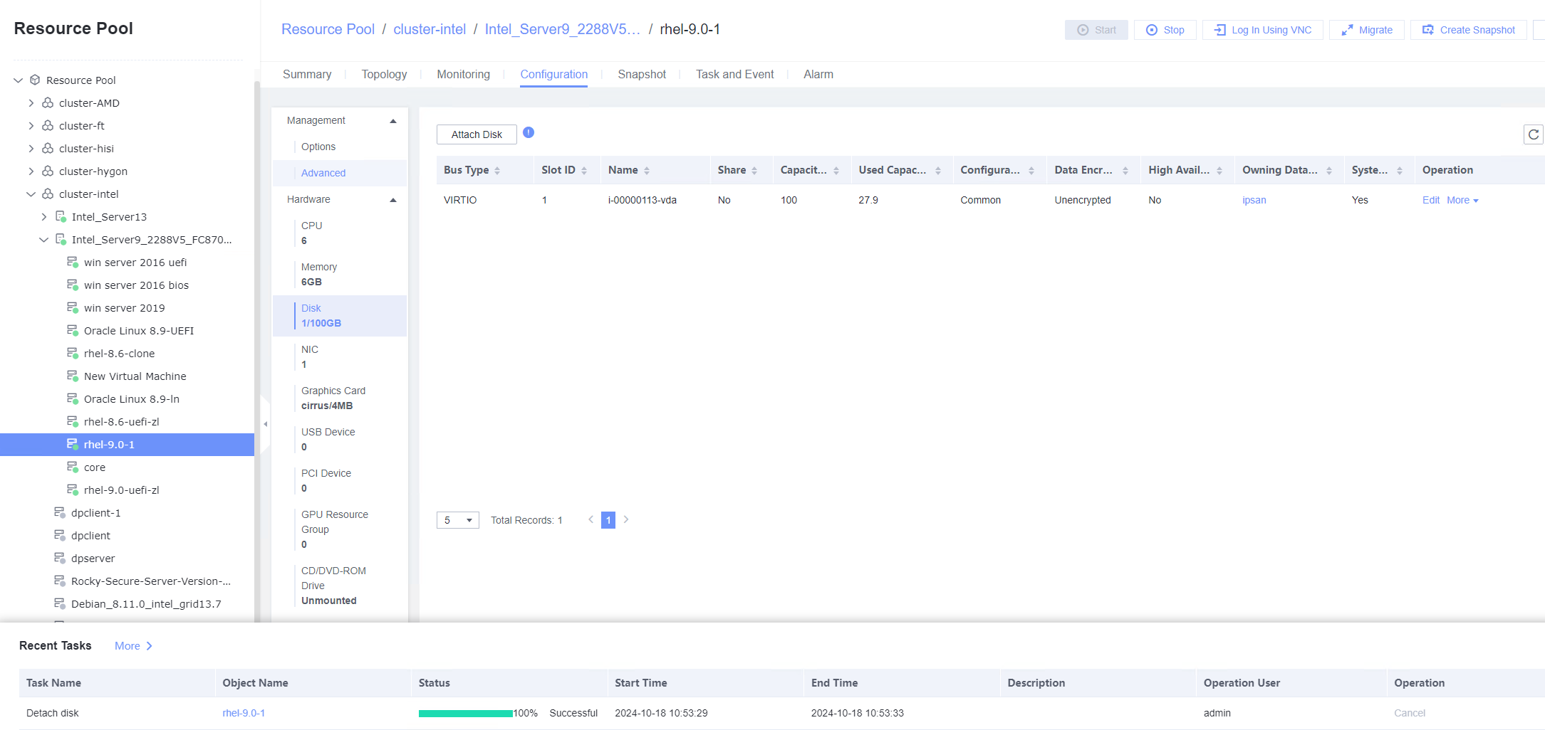
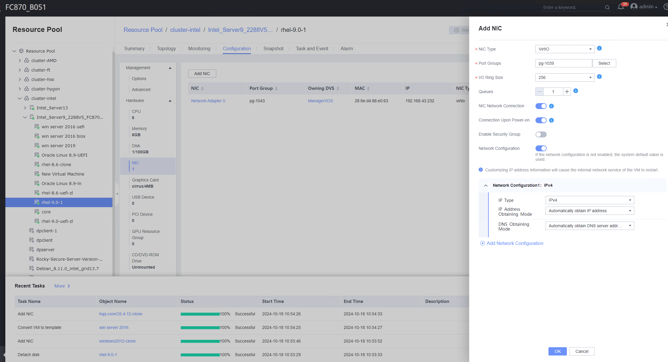
 2. Configure the IP address and mask of the new NIC through DHCP or manual configuration. (Expected result 2)
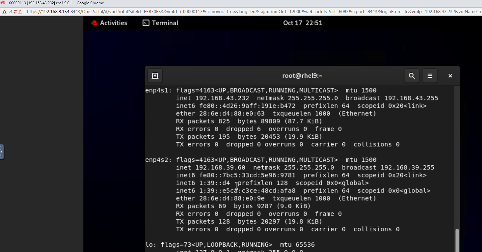
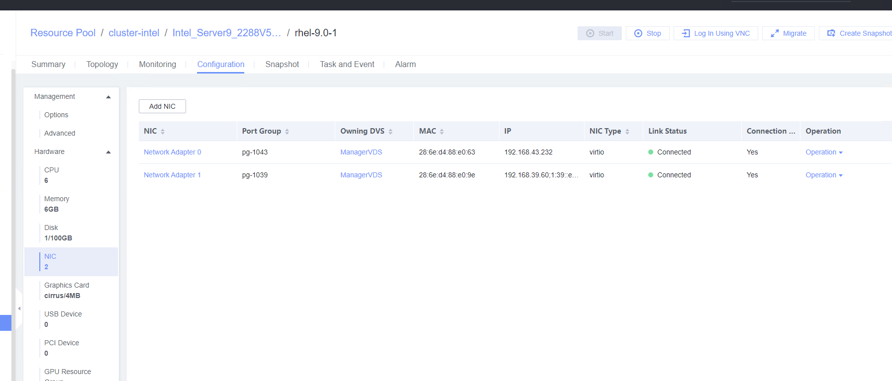
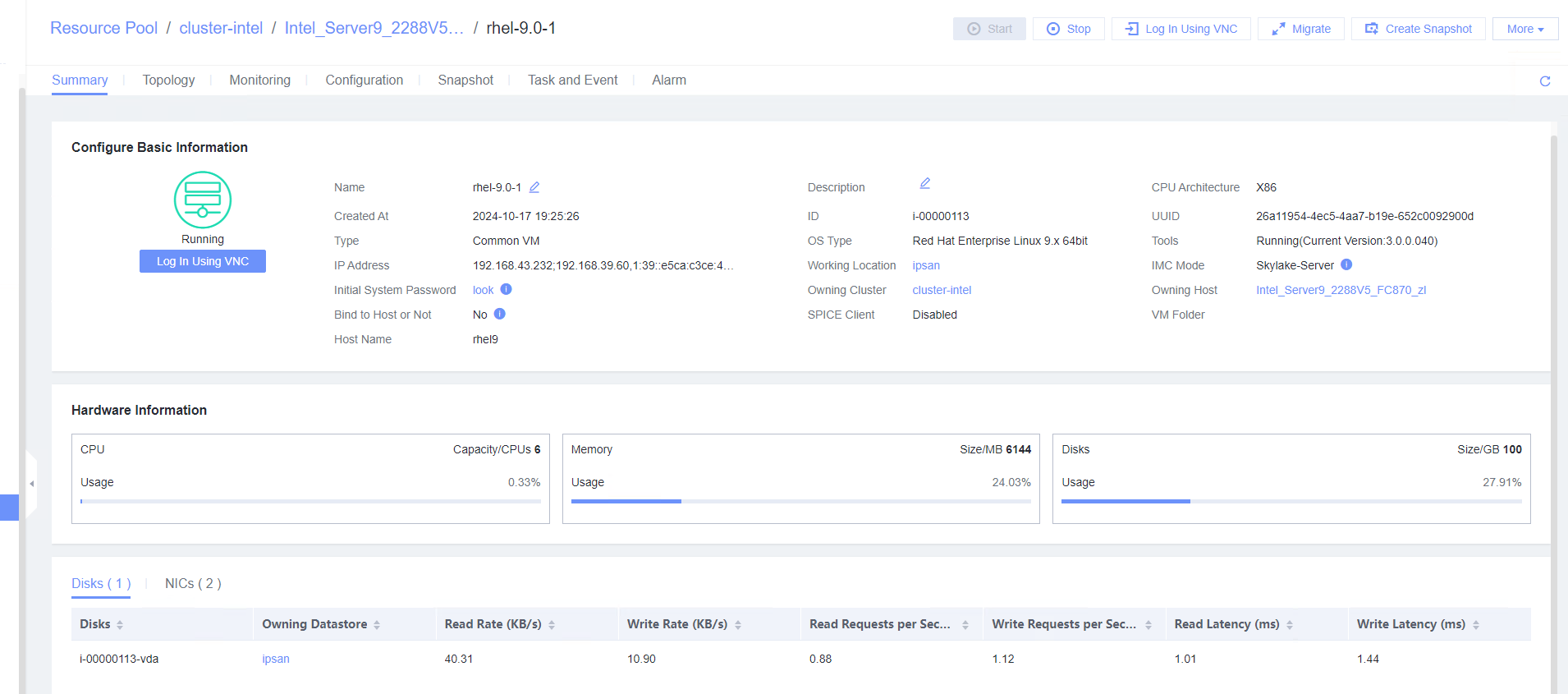
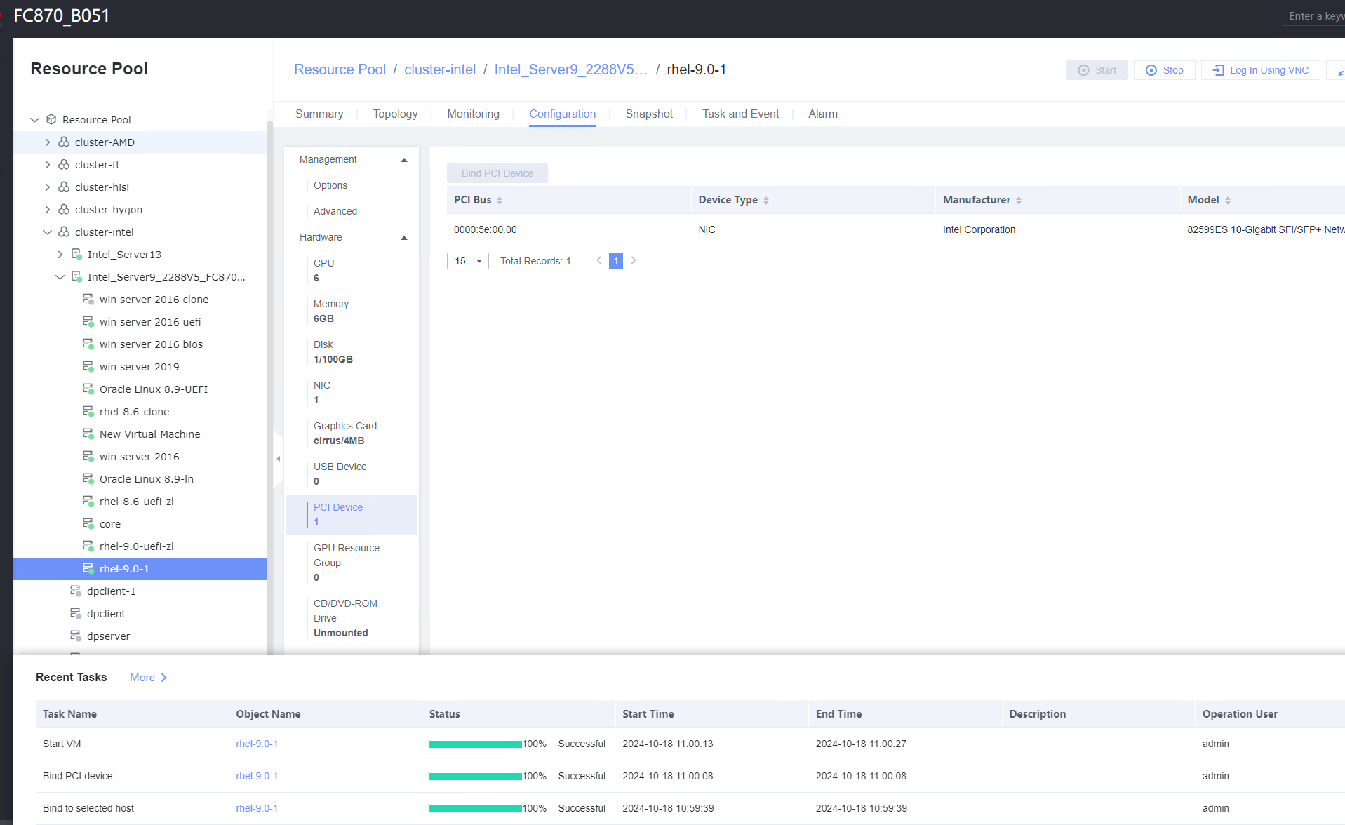 2. Configure the IP address and mask of the new NIC through DHCP or manual configuration. (Expected result 2)
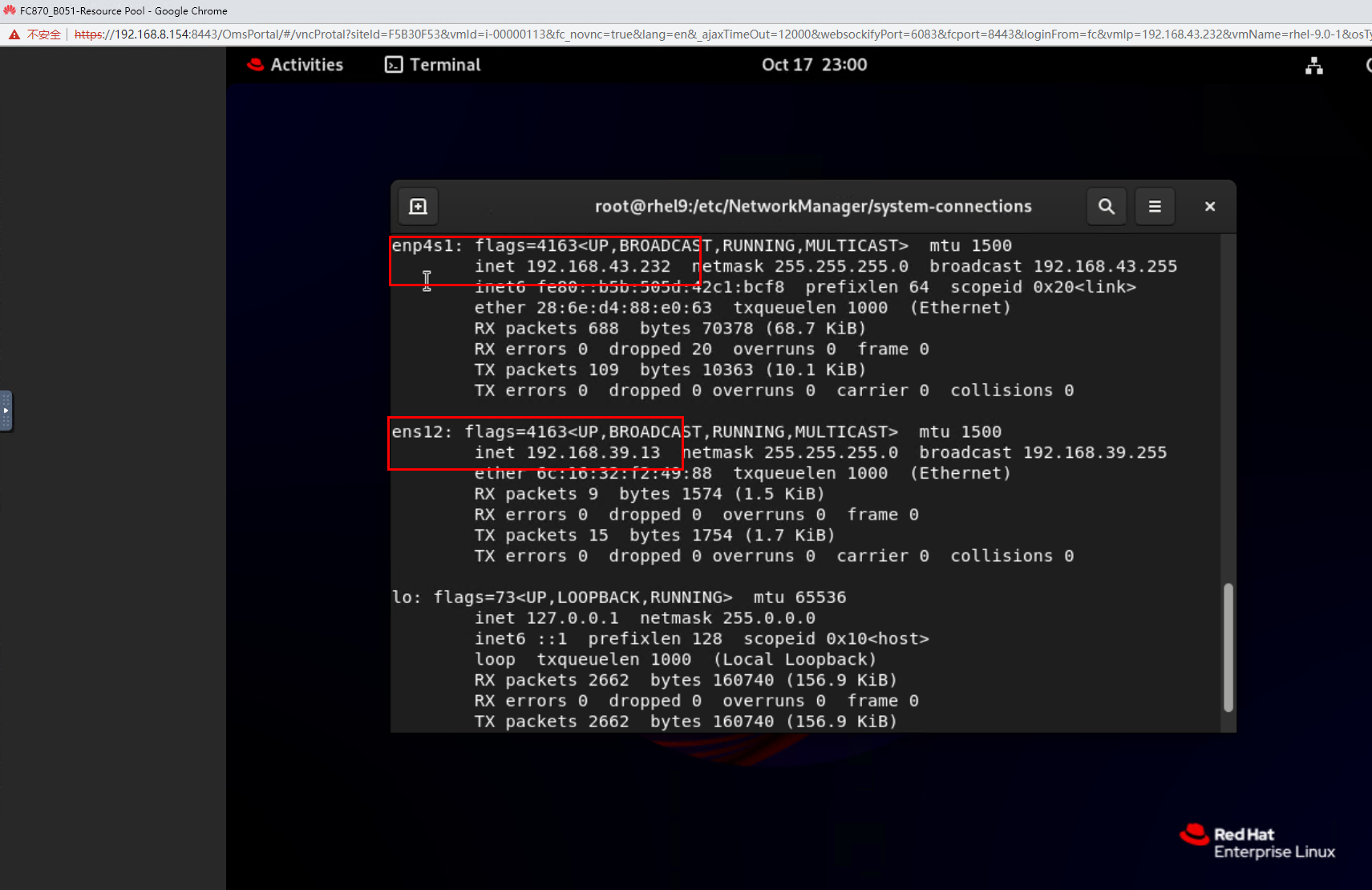
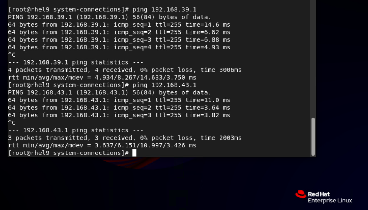 3. Select the VM, which is in the stopped state, choose Configuration > Hardware > PCI Device, select the NIC added in step 1, unbind the NIC, and start the VM. Then, run the ifconfig –a/ip link show command to view the VM NIC information. (Expected result 3)
 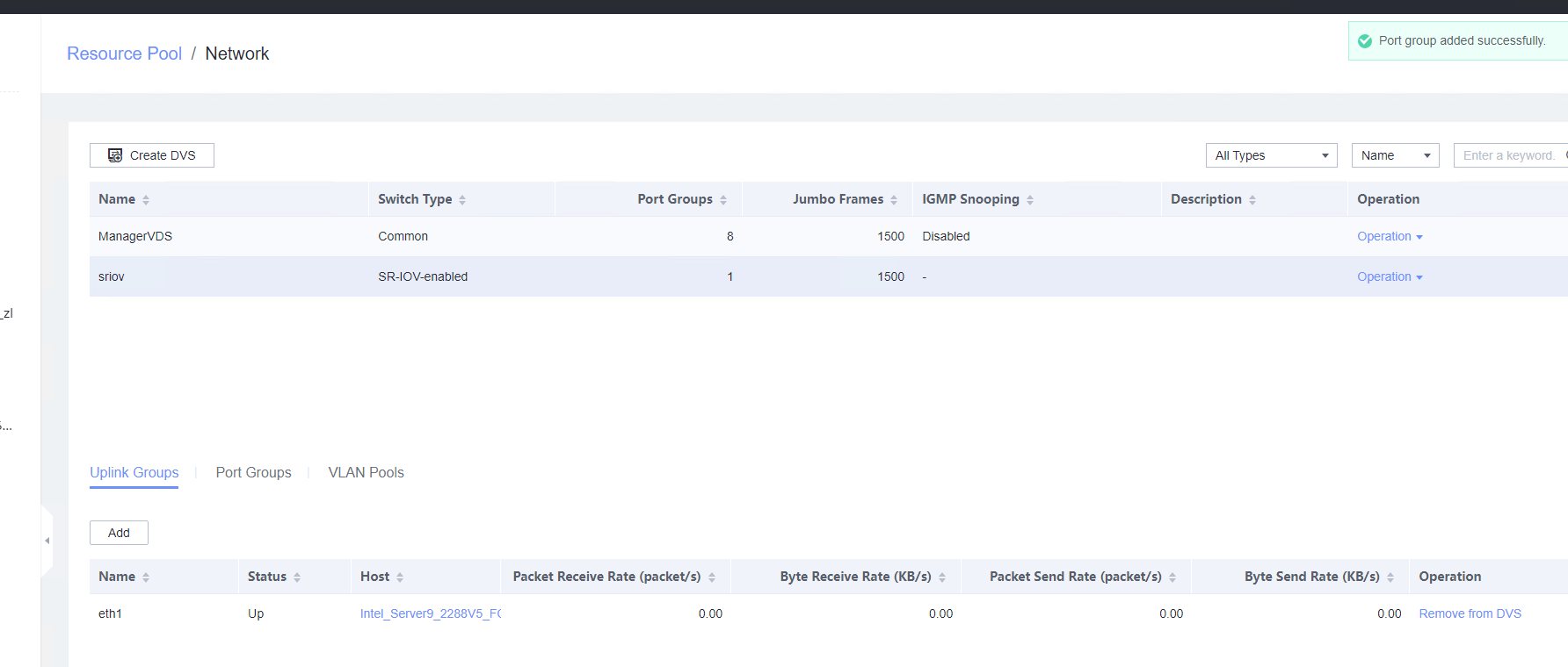 2. Choose Resource Pool > Network > Create DVS. In the displayed dialog box, create a DVS named SR-IOV1, set the switch type to SR-IOV-enabled, select Add Uplinks and Add VLAN Pool, and click Next. Select the network port for which the SR-IOV mode is configured in previous step and click Next. Then, click Add, enter a VLAN range from 2 to 4094, click Next, and click OK. (Expected result 2)
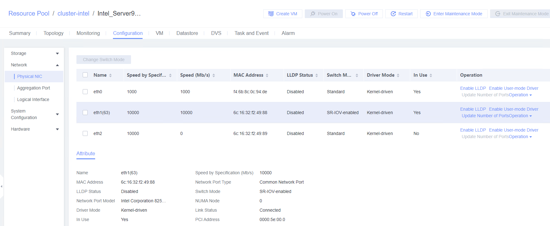 3. Choose Resource Pool > Network, select SR-IOV1 created in the previous step, click the Port Groups tab, and click Add to add port group pg1. Set Port Type to Access, configure other parameters, and click Next. Set Connection Mode to VLAN, set the VLAN ID, and click Next. After confirming all information, click OK. (Expected result 3)
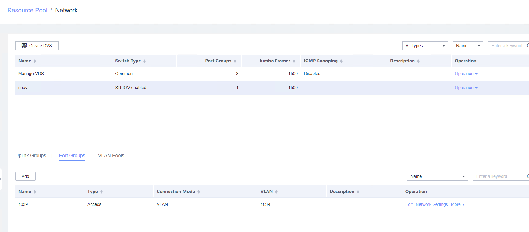 4. In the resource pool, locate the VM created in step 1. When the VM is stopped, click the VM name and choose Configuration > Hardware > NIC. Then, locate the NIC and choose Operation > Modify Port Group, select SR-IOV1 created in step 2 for the DVS and pg1 for the port group, and click OK. (Expected result 4)
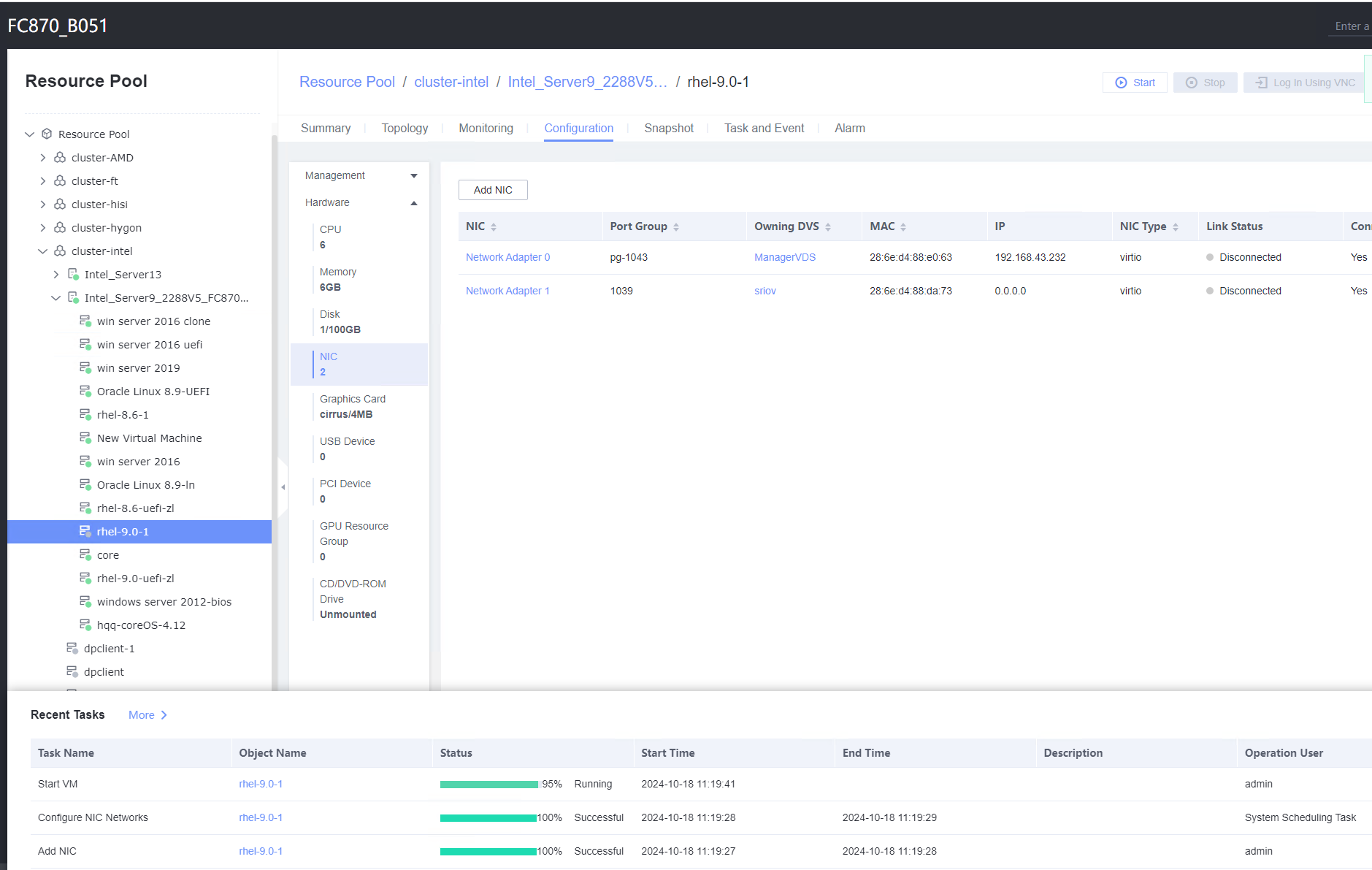 5. Start the VM, configure the IP address and mask of the new NIC through DHCP or manual configuration, and run the ifconfig –a/ip link show command to view the VM NIC information. (Expected result 5)
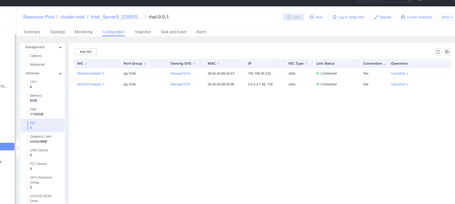
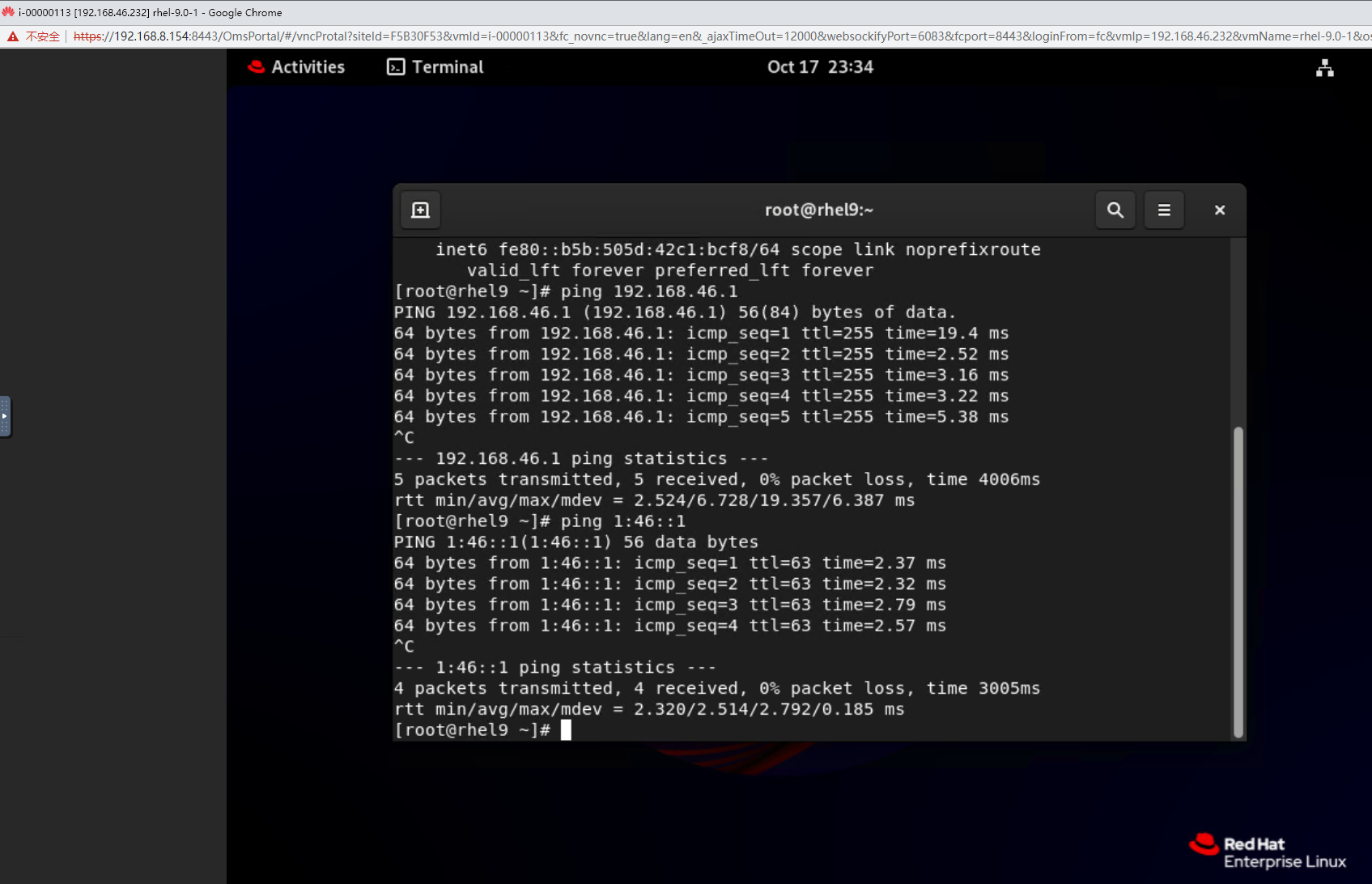
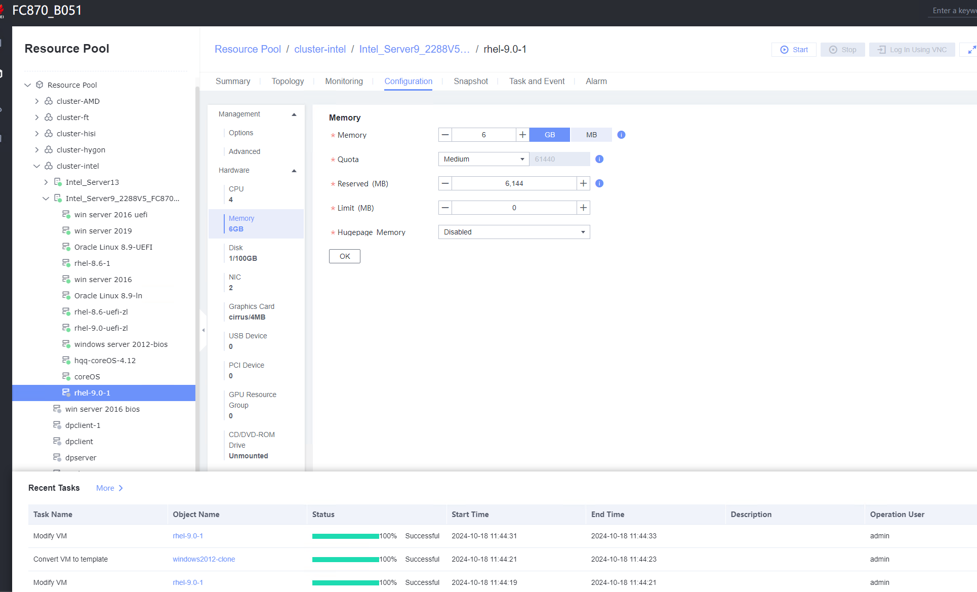


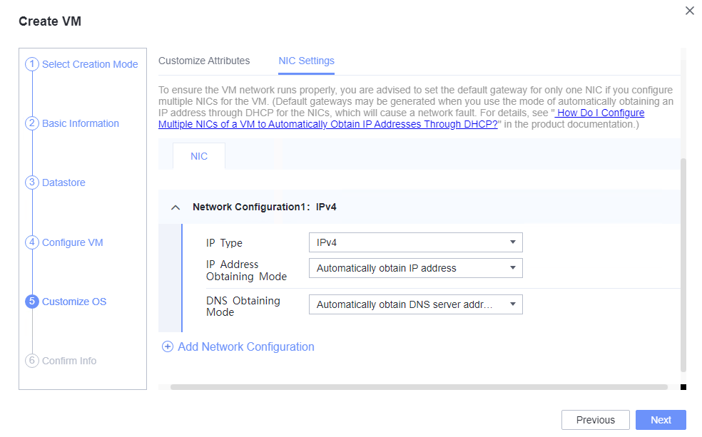 2. Customize NIC settings, set IP Type to IPv4, IP Address Obtaining Mode to Automatically obtain IP address, and DNS Obtaining Mode to Automatically obtain DNS server address. (Expected result 2)
