Container Storage Solution
Best Practice of OCPV Based on OceanStor Dorado SAN
Date 2025-06-30
![]()
Axians Global
All Rights Reserved
About This Document
Purpose
This document provides a technical solution of connecting OceanStor Dorado all-flash storage to the OpenShift container platform (OCP) 4.16 through the Huawei Container Storage Interface (CSI) plug-in over the Fibre Channel (FC) network. This document tests the dynamic provisioning, capacity expansion, and snapshot management of storage volumes through Huawei CSI plug-in, and verifies that the PersistentVolumeClaims (PVCs) created through the CSI can be successfully mounted to system disks and data disks of VMs. This document also verifies the full-lifecycle management capabilities of OpenShift Virtualization VMs, including live migration of VMs in raw block mode as well as VM creation and deletion. The solution described in this document proves that Huawei OceanStor Dorado can be integrated with OpenShift Virtualization to provide enterprises with a high-performance and high-reliability cloud-native virtualization storage solution.
Change History
Issue | Date | Description |
|---|---|---|
01 | 2025-06-30 | This issue is the first official release. |
1 Solution Introduction
1.1 Overview
OpenShift Container Platform Virtualization (OCPV) provides a container platform virtualization environment for VM applications and is widely used by customers. The container storage solution uses Huawei SAN storage as the foundation, which is integrated with OCPV using Huawei CSI plug-in, implementing dynamic creation, capacity expansion, and deployment of PVC resources, as well as fast creation, deletion, and migration of VMs. This brings high performance, high reliability, and easy O&M. This solution uses the Fibre Channel network as an example to demonstrate the capabilities and advantages of the container storage solution in OCPV scenarios.
1.2 Product Introduction
OceanStor Dorado Storage Systems
OceanStor Dorado storage systems are Huawei’s brand-new all-flash storage products designed for medium- and large-size enterprise storage environments. The storage systems leverage the flash-dedicated FlashLink® technique to provide mass data storage, fast data access, high availability, and excellent utilization in the ease-of-use and energy saving form factor. OceanStor Dorado offers comprehensive and superb solutions by using diverse efficiency boost mechanisms to provide industry-leading performance. Those solutions help customers maximize their return on investment (ROI) and meet the requirements of different containerized applications.
In addition to providing enterprise users with high-performance and efficient storage services, OceanStor Dorado supports advanced data backup and DR technologies, ensuring secure and smooth running of data services. Also, OceanStor Dorado offers easy-to-use management modes and convenient local/remote maintenance modes, greatly decreasing the management and maintenance costs.
OpenShift Platform and OpenShift Virtualization
OpenShift is an enterprise-level container platform built by Red Hat based on Kubernetes. It provides a complete solution for containerized application development, deployment, and management.
OpenShift Virtualization (formerly known as container native virtualization, CNV) is an add-on to OpenShift that allows you to run and manage VM workloads on OpenShift.
The core features are as follows:
- KubeVirt-based: KubeVirt is used to run VMs on Kubernetes.
- Unified management
– Containers and VMs are managed on the same console.
– The same kubectl/oc CLI tool is used. - Modernization of traditional applications
– Containerization of traditional VM workloads
– Migration of traditional VMs to containers - Advanced virtualization functions
– Snapshot
– Live migration
Huawei CSI Plugin
Container storage interface (CSI) is an industry standard used to expose block and file storage systems to containerized workloads on container platforms such as Kubernetes. Huawei CSI plug-in is used to communicate with Huawei enterprise storage and scale-out storage products and provide storage services for Kubernetes containerized workloads. It is a mandatory plug-in used by Huawei enterprise storage and scale-out storage in a Kubernetes environment.
- Kubernetes uses a series of officially maintained sidecar components to register and monitor Kubernetes object resources and invoke CSI Driver when necessary.
- The Huawei CSI plug-in implements the invocation initiated by sidecar on Huawei storage. For example, the operation of creating a PersistentVolume (PV) is implemented as creating a LUN or file system on Huawei storage.
– CSI Controller: a pod that runs independently in Deployment mode. It is used to interact with storage and create and delete resources on the storage side, such as creating a LUN or file system and expanding capacity.
– CSI Node: a pod that runs on Kubernetes worker nodes in DaemonSet mode. It is used to mount, unmount, or format a LUN/file system provided by Huawei storage on worker nodes. - Huawei storage provides SAN/NAS storage resource services for Kubernetes worker nodes through multiple protocols. Huawei storage communicates with Huawei CSI plug-in drivers through RESTful.
Solution Advantages
- Intuitive and convenient resource management
Containerized VM management makes monitoring and allocation of storage resources intuitive, simplifying O&M. - Fast resource provisioning and configuration, ensuring better service continuity
During node replacement, upgrade, and maintenance, the CSI plug-in supports SAN storage access in RWX mode, implementing smooth VM service migration and improving VM service continuity. - Higher migration performance
Huawei flash storage provides high-performance data migration capabilities to migrate data within a VM or between VMs in the background without affecting foreground services.
2 Solution Planning
2.1 Solution Networking
Solution networking
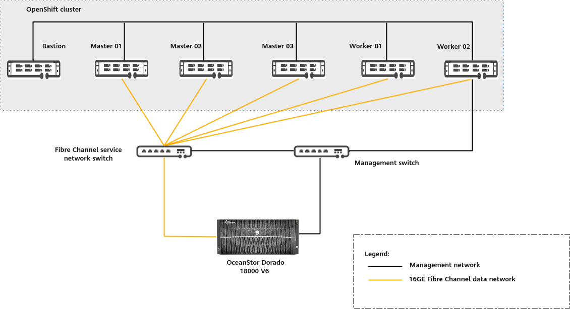
Networking description:
- The management network enables network communication between nodes in the cluster.
- In the production environment, it is recommended that three master nodes be deployed in the OpenShift cluster for high availability (HA). The number of worker nodes can be increased to adapt to services. Routine O&M of the OpenShift cluster is performed on the bastion node.
- The service network is a Fibre Channel network. Each node in the OpenShift cluster is equipped with a host bus adapter (HBA) and physically connected to the Fibre Channel switch. Each controller of OceanStor Dorado is equipped with an HBA and connected to the Fibre Channel switch. Zones are created on the Fibre Channel switch and the WWNs of the hosts and storage HBAs are added to the same zone. In this way, the hosts communicate with the storage system over the Fibre Channel network and the cluster applies for block services from Huawei OceanStor Dorado through the Fibre Channel network.
2.2 Configurations
Table 2-1 Hardware configurations
Hardware | Configuration | Quantity | Remarks |
|---|---|---|---|
| Controller enclosure: OceanStor Dorado 18000 V6 (four-controller) CPU: Kunpeng 920 (2.6 GHz, 128 cores per controller) Disk: 48 × 7.680 TB SSDs NIC: one 16GE Fibre Channel NIC for each controller |
|
|
| CPU: 2 x Kunpeng 920-4826 Memory: 24 x 32 GB Disk: 4 x 1.92 TB SSDs Network: 16GE Fibre Channel NIC |
|
|
|
|
|
|
|
|
|
|
Table 2-2 Software configurations
Software | Version | Remarks | Download Link |
|---|---|---|---|
|
|
| |
openshift-client | 4.16.30 | oc client | |
rhcos | 4.16.3 | Cluster CoreOS | https://mirror.openshift.com/pub/openshift-v4/dependencies/rhcos/ |
Huawei CSI | V4.6.0 | CSI | |
OceanStor Dorado 18000 V6 | V700R001C00SPC200 | Software version of the storage system |
2.3 Network Planning
Table 2-3 shows the network planning of the best practice.
Table 2-3 Network planning
Network Name | Network Segment | Device | Port | Switch |
|---|---|---|---|---|
| 192.168.1.* |
|
|
|
|
|
| ||
master1.ocp4.example.com |
| Gigabit switch | ||
|
|
| ||
|
|
| ||
|
|
| ||
|
|
| ||
|
|
|
|
|
|
|
| ||
|
|
| ||
|
|
| ||
|
|
| ||
|
|
|
|
|
|
|
|
2.4 Storage Planning
- Multiple storage pools can be configured for a storage system. Each storage pool uses different disks so that disks of the same storage system are physically isolated using storage pools. Configure one or more storage pools based on your requirements. In the best practice, one storage pool is created to simplify management.
Configure the storage pool as follows:
Storage pool name: StoragePool001
RAID policy: RAID 6
Hot spare policy: High (2 disks)

For details about the storage configuration process, see Configure > Basic Storage Service Configuration Guide for Block in OceanStor Dorado 8000 V6 and Dorado 18000 V6 Series 6.1.x & V700R001 Product Documentation.
3 Test and Verification Procedure
3.1 Installing the OpenShift Cluster
3.2 Installing OpenShift Virtualization
3.4 Configuring the Storage System
3.6 Verifying OceanStor Dorado SAN–based OCPV
3.1 Installing the OpenShift Cluster
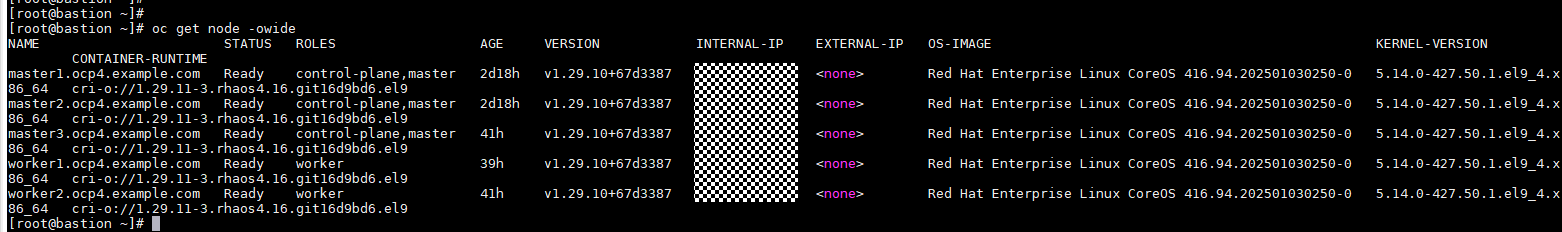
- Set up an OpenShift cluster according to the official installation guide and run the following command to check whether the OpenShift cluster is deployed:
oc get node -o wide
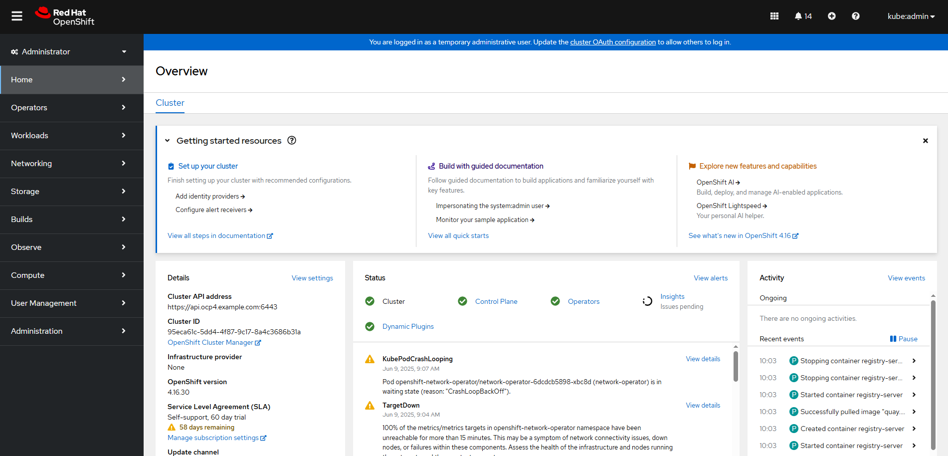
- Log in to the OpenShift web client.
a. Run the following command to view the console information:
oc get route –all-namespaces |grep console-openshift

b. Enter the following domain name in the address box of a browser for login:
https://console-openshift-console.apps.ocp4.example.com
3.2 Installing OpenShift Virtualization
Install OpenShift Virtualization based on the environment requirements by referring to OpenShift Virtualization installing. The best practice describes only the basic installation process.
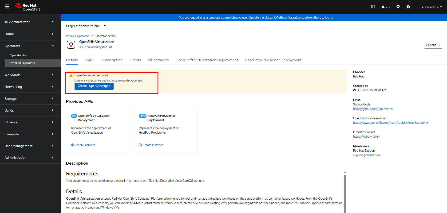
Step 1 Log in to the OpenShift web console, choose Operator > OperatorHub, and click the search box on the right.
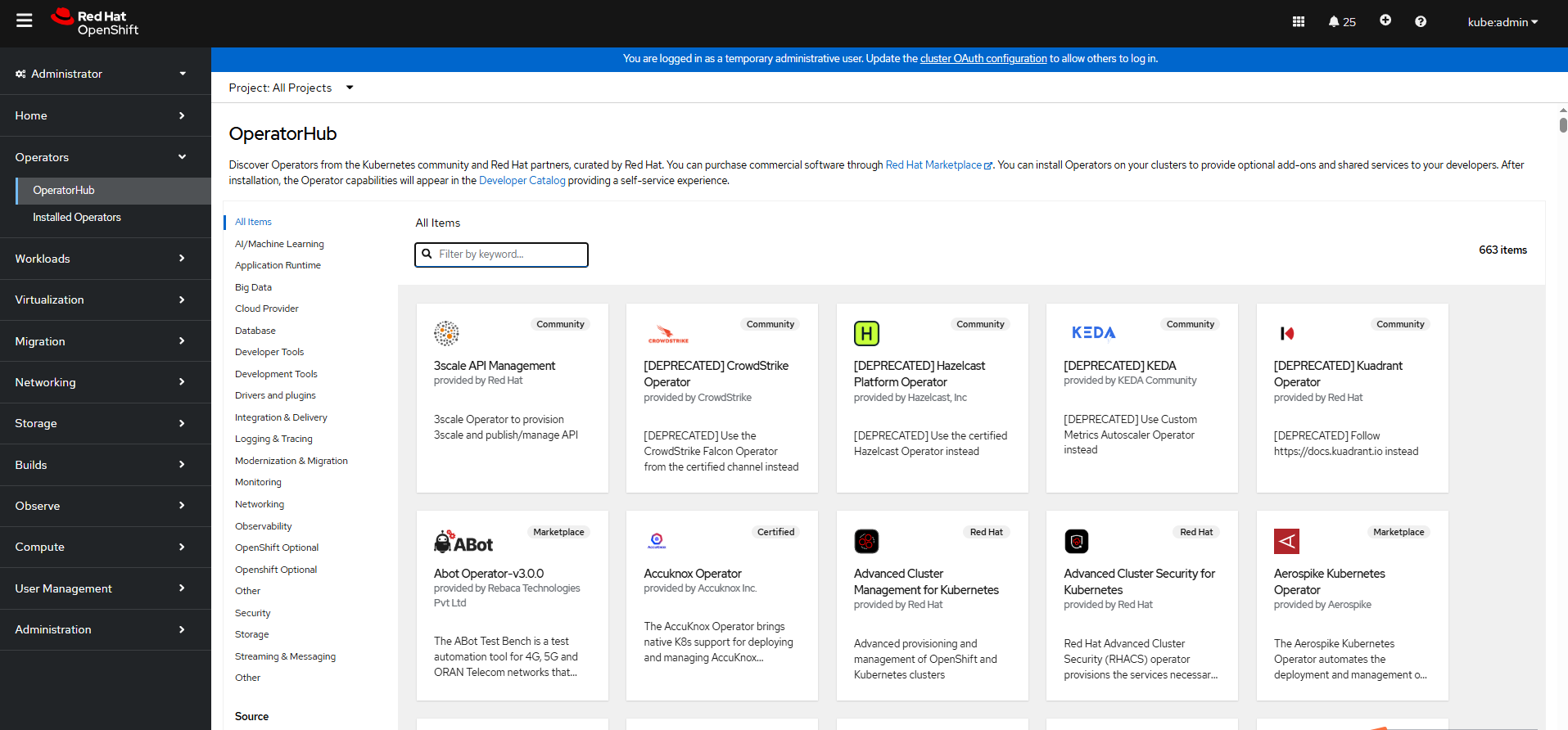
Step 2 Enter Virtualization to display OpenShift Virtualization.
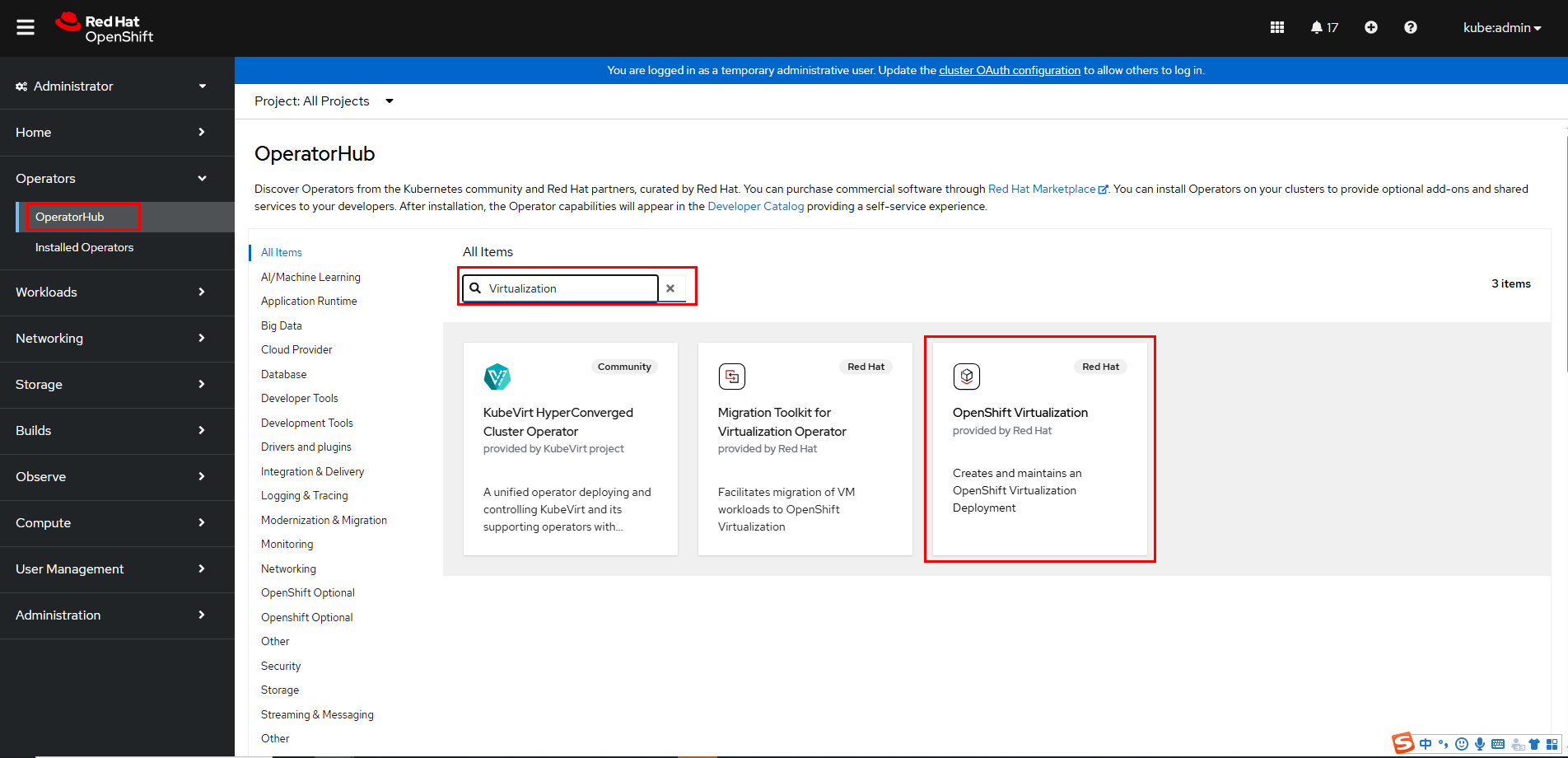
Step 3 Click OpenShift Virtualization and install it.
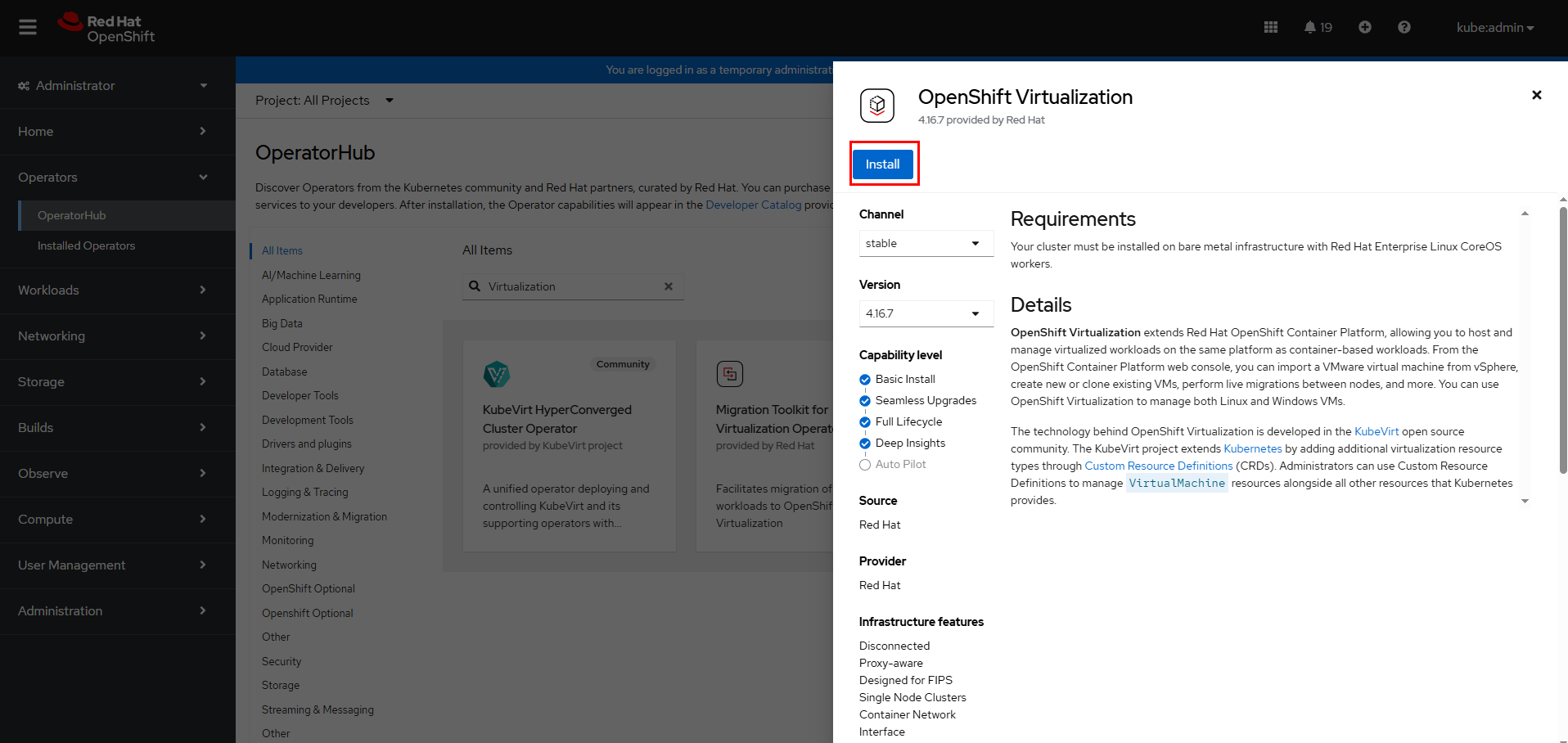
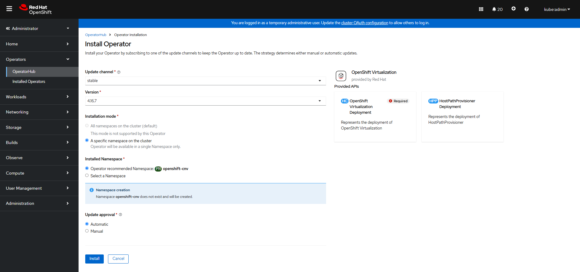
Step 4 On the Install Operator page, confirm the namespace and click Install. Wait until the installation is complete.
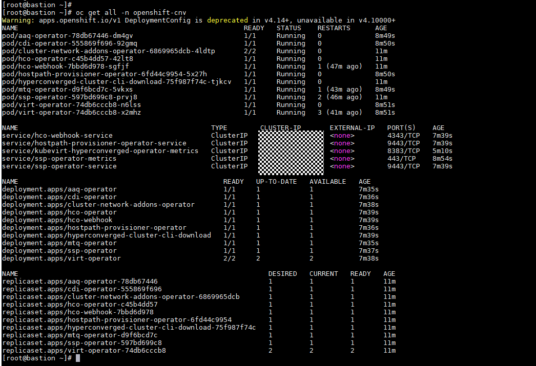
Step 5 Run the following command to check the OpenShift Virtualization running status. If the pods are in the Running state, OpenShift Virtualization is properly installed.
oc get all -n openshift-cnv
Step 6 Create a HyperConverged Operator (HCO). (As the unified entry of virtualization, the HCO provides deployment and management capabilities for OpenShift Virtualization and its auxiliary operators through default configurations, and automatically generates custom resources (CRs) corresponding to these operators.)
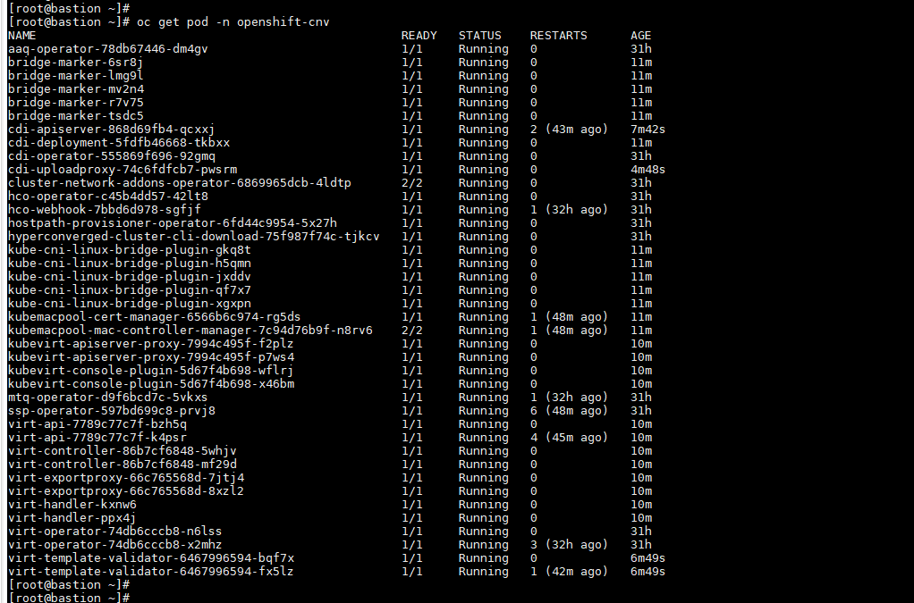
Step 6 After the installation is complete, run the following command to verify that all pods are in the Running state:
oc get pod -n openshift-cnv
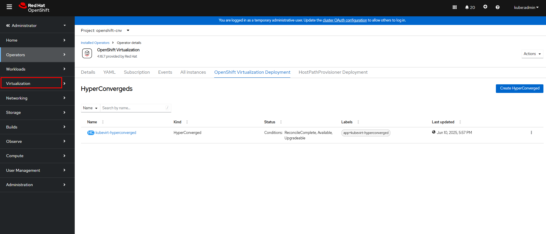
Step 8 After the HyperConverged deployment is complete, refresh the OpenShift web console. Virtualization is displayed in the navigation tree, and all virtualization configuration operations can be performed under the navigation menu.
3.3 Installing kubevirt
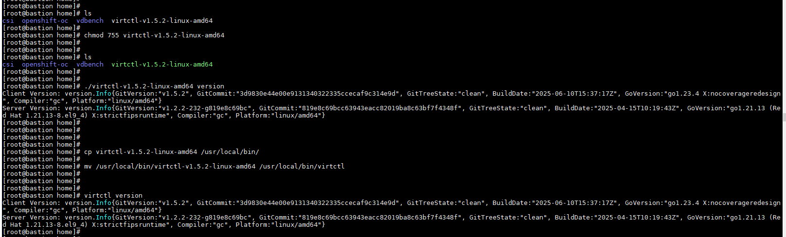
Download kubevirt and upload it to the bastion node for subsequent CLI operations (version 1.5.2 is used in this example).
chmod 755 virtctl-v1.5.2-linux-amd64
cp virtctl-v1.5.2-linux-amd64 /usr/local/bin/
mv /usr/local/bin/virtctl-v1.5.2-linux-amd64 /usr/local/bin/virtctl
3.4 Configuring the Storage System
Step 1 Initialize the storage system by following the instructions in Initialization Guide of OceanStor Dorado 8000 and Dorado 18000 Product Documentation.
Step 2 Establish Fibre Channel connections between the hosts and the storage system by following the instructions in « Establishing Fibre Channel Connections » in OceanStor Dorado and OceanStor 6.x and V700R001 Host Connectivity Guide for Red Hat.
3.5 Installing Huawei CSI
Step 1 Install the CSI by referring to « Installation and Deployment » > « Installation Preparations » in eSDK Huawei Storage Kubernetes CSI Plugins V4.6.0 User Guide.
Step 2 Run the following command to verify that the Huawei CSI plug-in has been installed in the OpenShift cluster:
oc get pod -n huawei-csi -o wide

Step 3 Install the multipathing software by referring to « 4 Installation and Deployment » > « 4.1 Installation Preparations » > « 4.1.5 Checking the Host Multipathing Configuration » in eSDK Huawei Storage Kubernetes CSI Plugins V4.6.0 User Guide.
In this example, the native multipathing software of the operating system is used. For details about how to configure the multipathing software, see « Configuring Multipathing » > « Non-HyperMetro Scenarios » > « OS Native Multipathing Software » in OceanStor Dorado and OceanStor 6.x and V700R001 Host Connectivity Guide for Red Hat.
—-End
3.6 Verifying OceanStor Dorado SAN–based OCPV

Before performing the following operations, complete the installation and deployment from 3.1 Installing the OpenShift Cluster to 3.5 Installing Huawei CSI.
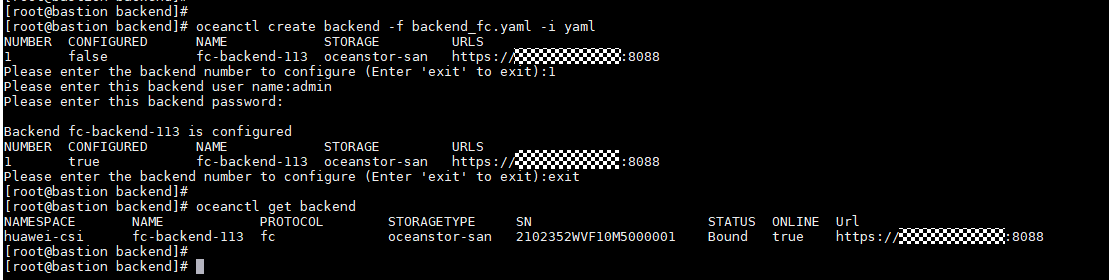
3.6.1 Creating a Backend
Create a Fibre Channel storage backend by referring to « Creating a Storage Backend » in eSDK Huawei Storage Kubernetes CSI Plugins V4.6.0 User Guide.
Run the following command to create and view the Fibre Channel backend in the OpenShift cluster. In this example, the backend name is fc-backend-113.
oceanctl create backend -f 6.1 backend_fc.yaml -i yaml
oceanctl get backend
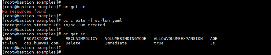
3.6.2 Creating an SC
On the OpenShift cluster, use the backend fc-backend-113 created in 3.6.1 Creating a Backend to create an SC. In this example, the SC name is sc-lun.
oc create -f 6.2 sc-fc.yaml
3.6.3 Creating a VM
Create a VM by using a proper method. For details about the methods, see Virtual machines. In this example, the custom OS method is used.
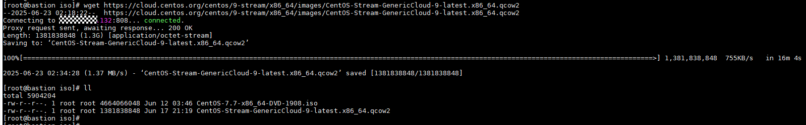
Step 1 Download the OS. In this example, CentOS 9 is used.
wget
https://cloud.centos.org/centos/9-stream/x86_64/images/CentOS-Stream-GenericCloud-9-latest.x86_64.qcow2
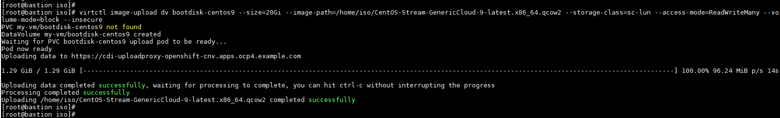
Step 2 Create a DataVolume that contains the OS image. (DataVolume is a mechanism that automatically imports VM disks to PVCs during the VM startup process. Without a DataVolume, users have to prepare a PVC with a disk image before assigning it to a VM. With a DataVolume, users do not have to manually create a PVC or import disks.) In this example, the DataVolume is bootdisk-centos9.
virtctl image-upload dv bootdisk-centos9 –size=20Gi
–image-path=/home/iso/CentOS-Stream-GenericCloud-9-latest.x86_64.qcow2
–storage-class=sc-lun –access-mode=ReadWriteMany –volume-mode=block –insecure
Step 3 On the OpenShift web console, click Virtualization > VirtualMachines > Create > From template.
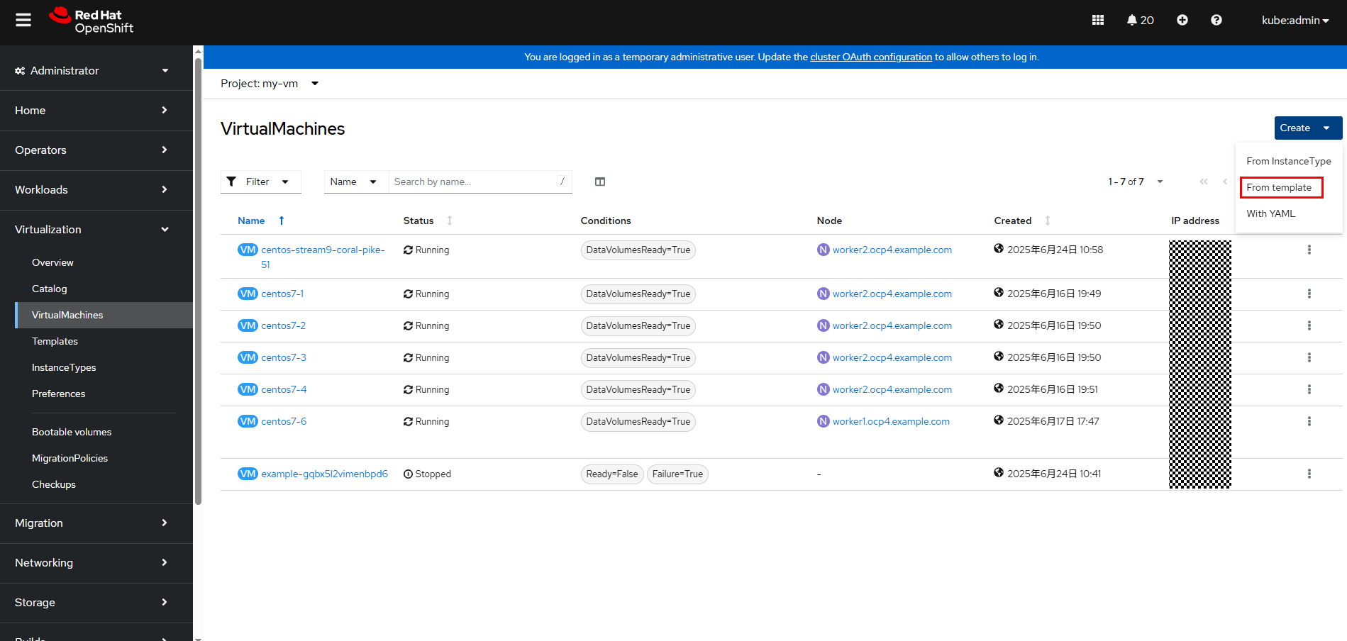
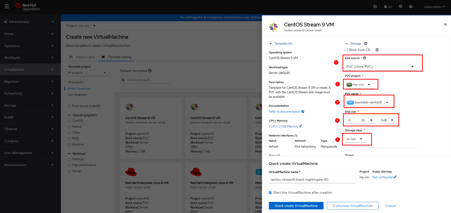
Step 4 On the Create new VirtualMachine page, select the project (namespace) for which you want to create a VM, and click CentOS Stream 9 VM. The page for customizing parameters is displayed.
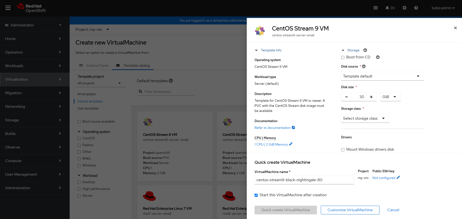
On the page for customizing parameters, expand Storage and set parameters as shown in the following figure. In this example, PVC name is bootdisk-centos9 created in Step 2, and Storage class is sc-lun created in 3.6.2 Creating an SC.
Step 5 Click Customize VirtualMachine to go to the page for confirming customized parameters, or click Quick create VirtualMachine to create a VM.
In this example, Customize VirtualMachine is clicked.
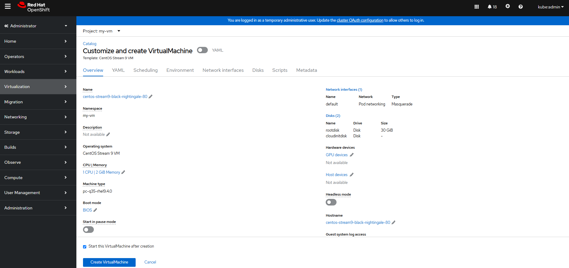
Step 6 Click Create VirtualMachine to create a VM. Wait until the VM configuration is complete.
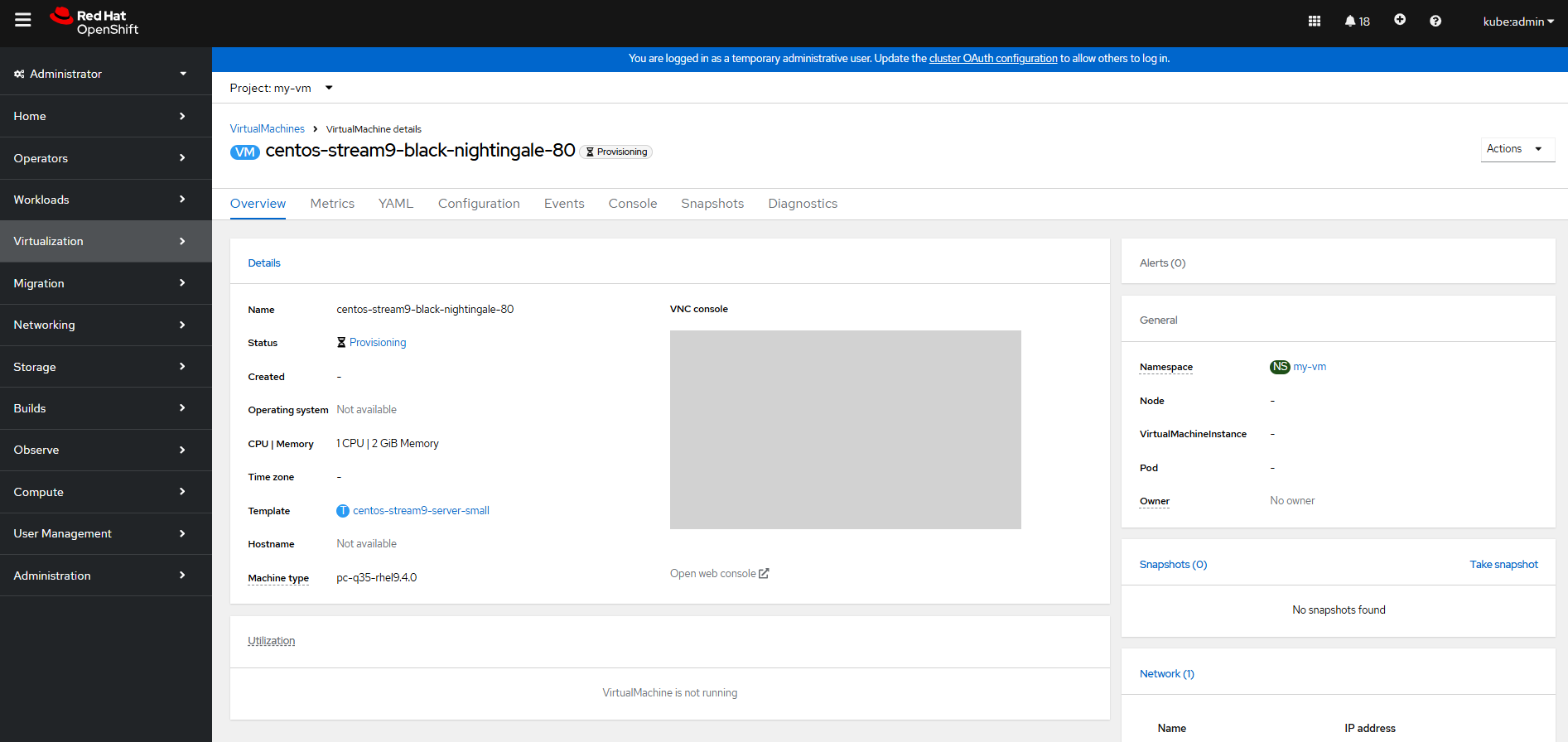
Wait until the VM status changes to Running.
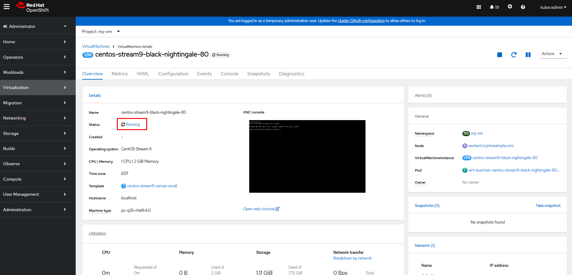
Step 7 Click Open web console to log in to the VM using VNC.
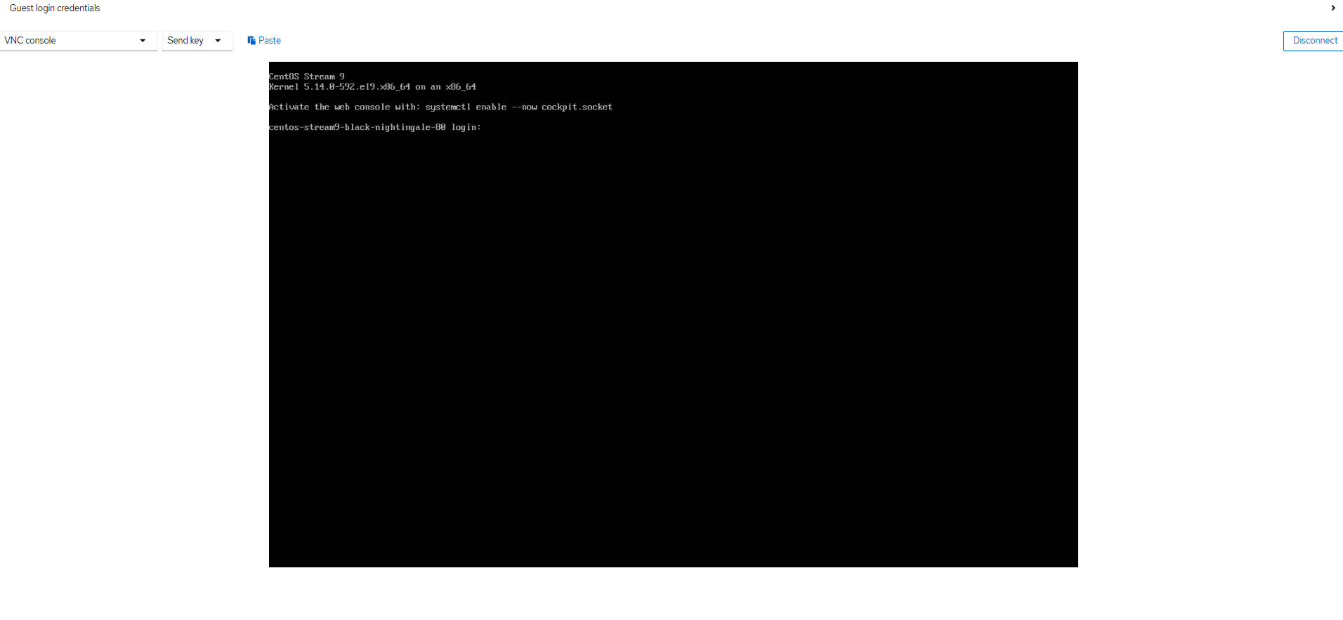
—-End
3.6.4 Configuring the VM Network
By default, the VM network created by OpenShift Virtualization is the cluster network. To enable access to a VM from an external network, you need to configure the external network for the VM. For details, see Networking.
In this example, the NMState operator is used to configure the VM network. (The NMState operator is a Kubernetes operator used to manage and configure the network status of cluster nodes. Based on the open-source project NMState, it provides a declarative method to manage network configurations of nodes in a Kubernetes cluster.)

In this example, the OpenShift nodes only have a single NIC for networking, so the only option for connecting VMs to the external network is to reuse the br-ex bridge that is configured by default for all nodes running in an OVN-Kubernetes cluster.
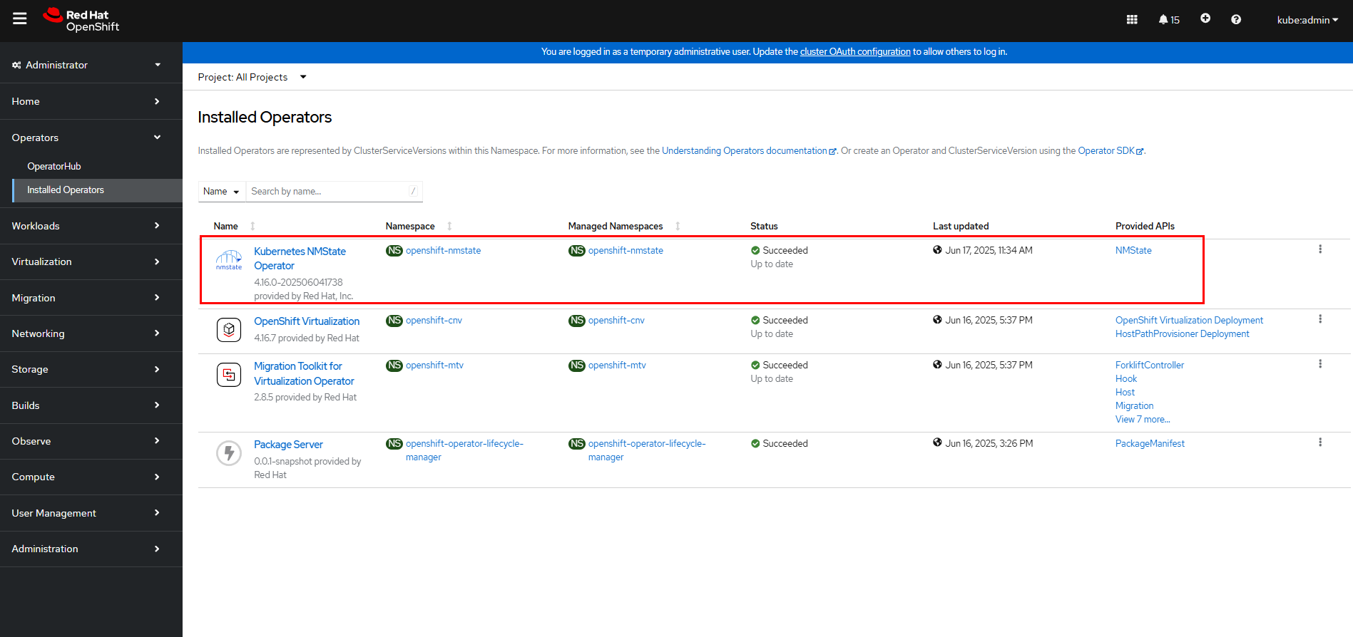
Step 1 Install the NMState operator: On the OpenShift web console, click Operators > OperatorHub, enter NMState in the search box, and then click Install.
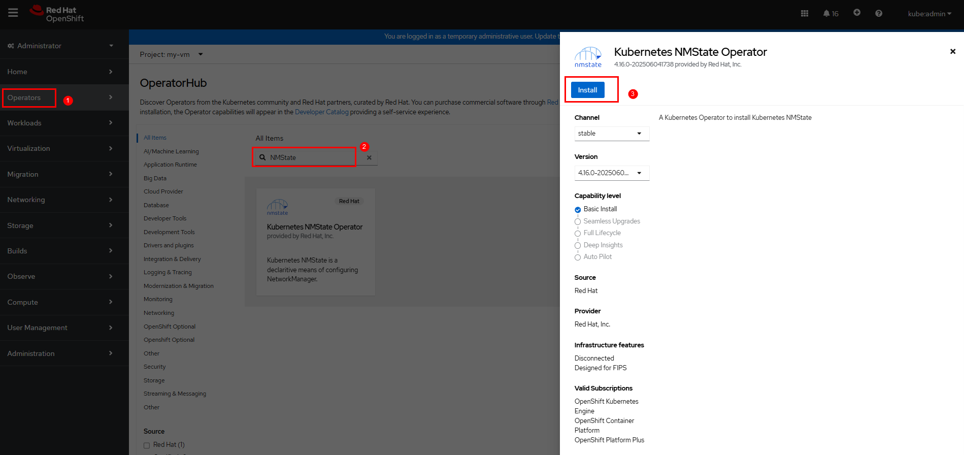
Wait until the installation is complete.
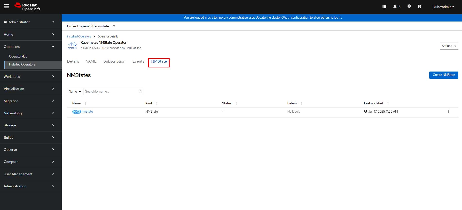
Step 2 Create an NMState instance: On the OpenShift web console, click Operators > Installed Operators > Kubernetes NMState Operator and click Create instance.
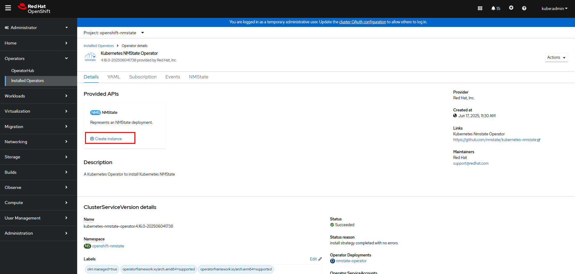
Wait until the NMState instance is created.
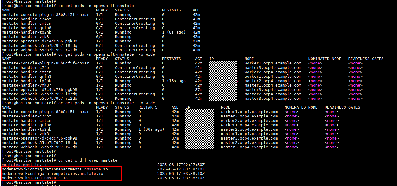
After the NMState instance is created, you can view three CRDs in the cluster: nodenetworkconfigurationenactments.nmstate.io, nodenetworkconfigurationpolicies.nmstate.io, and nodenetworkstates.nmstate.io. When network interfaces are configured on OpenShift, the network interfaces need to interact with them.
Step 3 Create a NodeNetworkConfigurationPolicy (NNCP): On the OpenShift web console, click Networking > NodeNetworkConfigurationPolicy > Create > With YAML to configure an NNCP.
The YAML content is as follows:
apiVersion: nmstate.io/v1
kind: NodeNetworkConfigurationPolicy
metadata:
name: br-ex-network
spec:
nodeSelector:
node-role.kubernetes.io/worker: »
desiredState:
ovn:
bridge-mappings:
– localnet: br-ex-network
bridge: br-ex
state: present
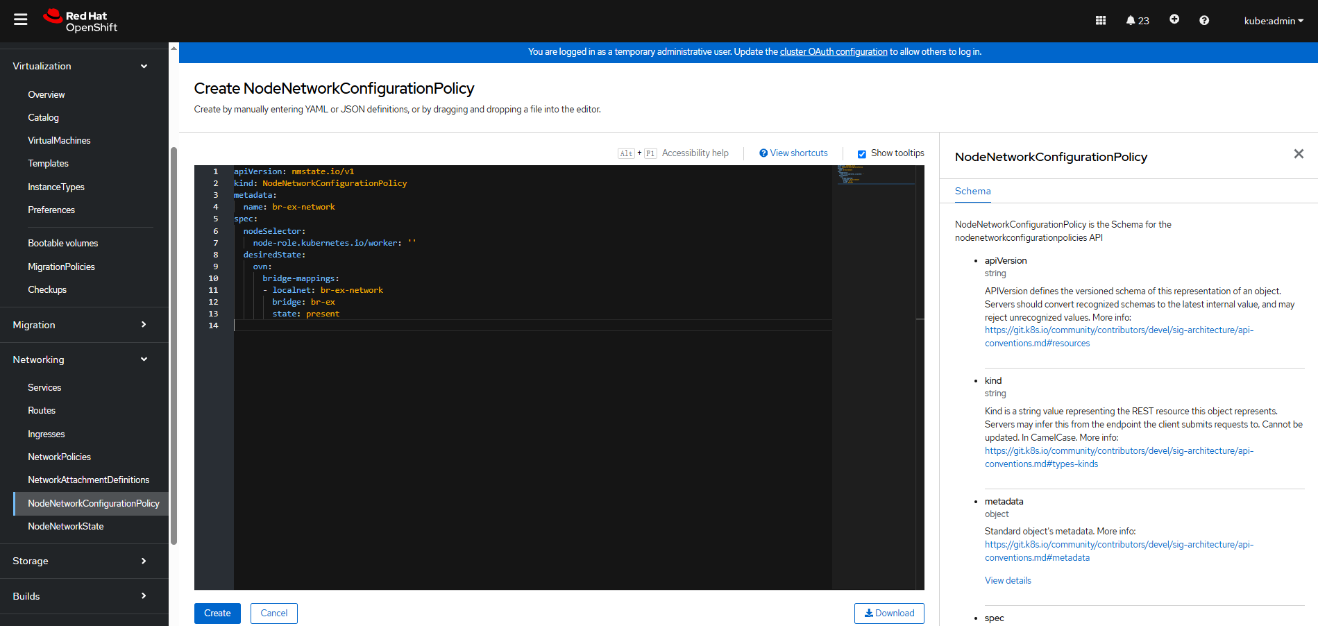
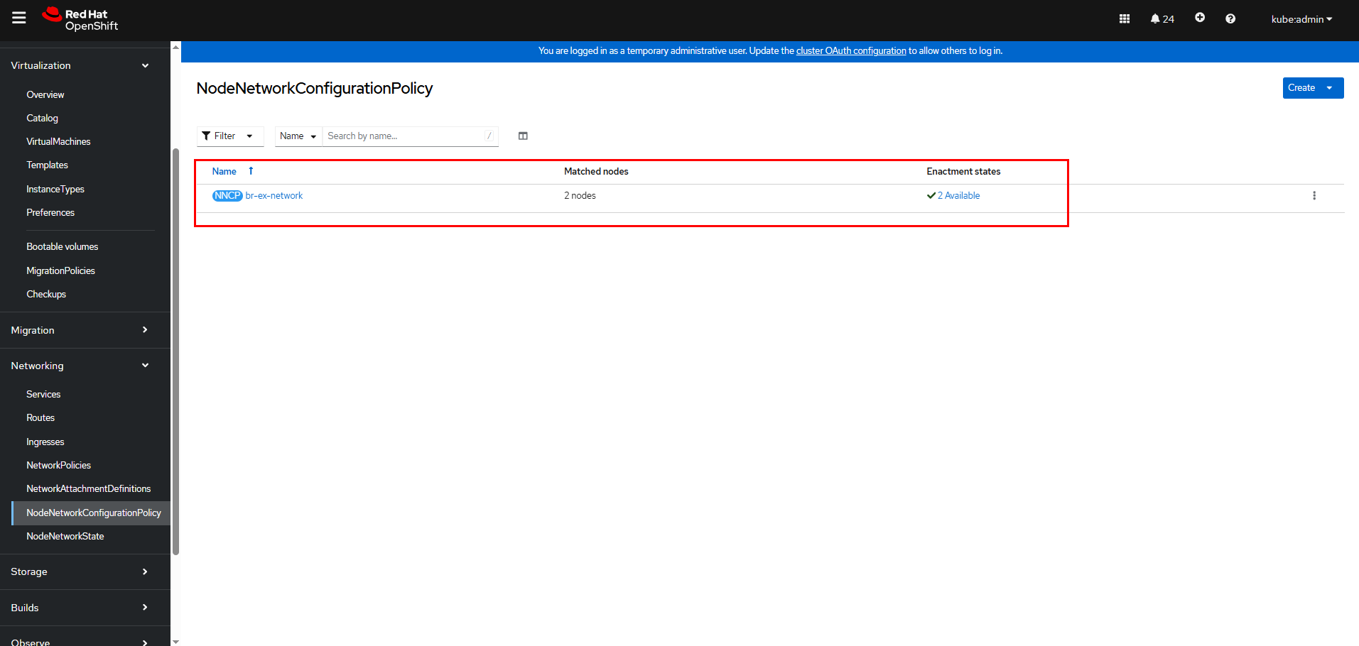
Click Create. Wait until the Enactment states of all nodes are Available.
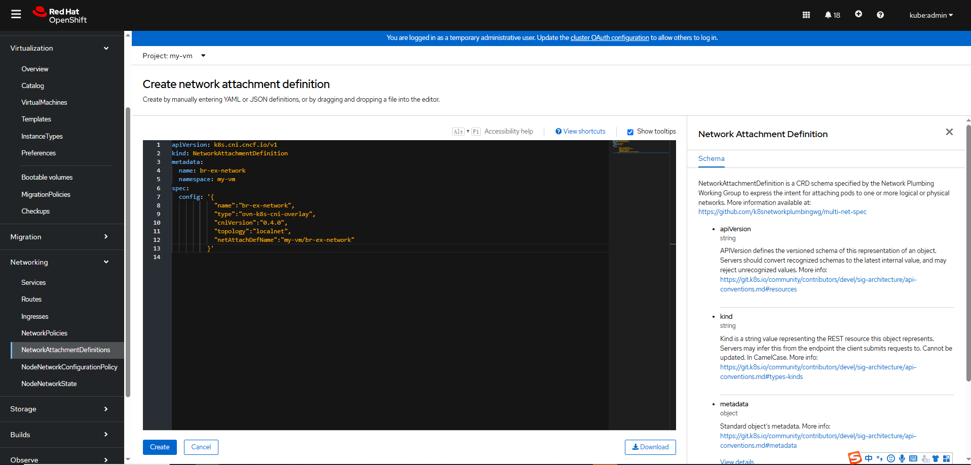
Step 4 Create a NetworkAttachmentDefinition: On the OpenShift console, click Networking > NetworkAttachmentDefinitions > Create Network Attachment Definition > Edit YAML to create one.
The YAML content is as follows:
apiVersion: k8s.cni.cncf.io/v1
kind: NetworkAttachmentDefinition
metadata:
name: br-ex-network
namespace: my-vm
spec:
config: ‘{
« name »: »br-ex-network »,
« type »: »ovn-k8s-cni-overlay »,
« cniVersion »: »0.4.0″,
« topology »: »localnet »,
« netAttachDefName »: »my-vm/br-ex-network »
}’

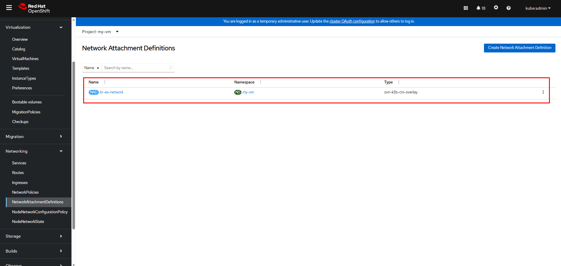
In the above NetworkAttachmentDefinition YAML, the name field in .spec.config corresponds to the localnet name of the NNCP. netAttachDefName is the combination of the namespace and name fields in .metadata, and the format is namespace/name (my-vm/br-ex-network in this example).
Click Create.
Step 5 Modify the networks and interfaces parts in the YAML for creating a VM in 3.6.3 Creating a VM to use the newly created external network, br-ex-network in this example, for the VM.
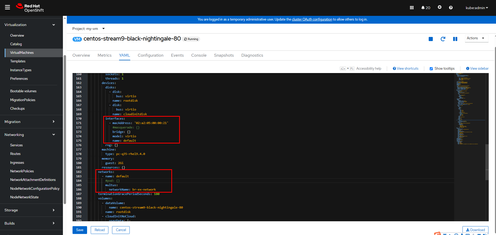
Click Save after the modification is complete.
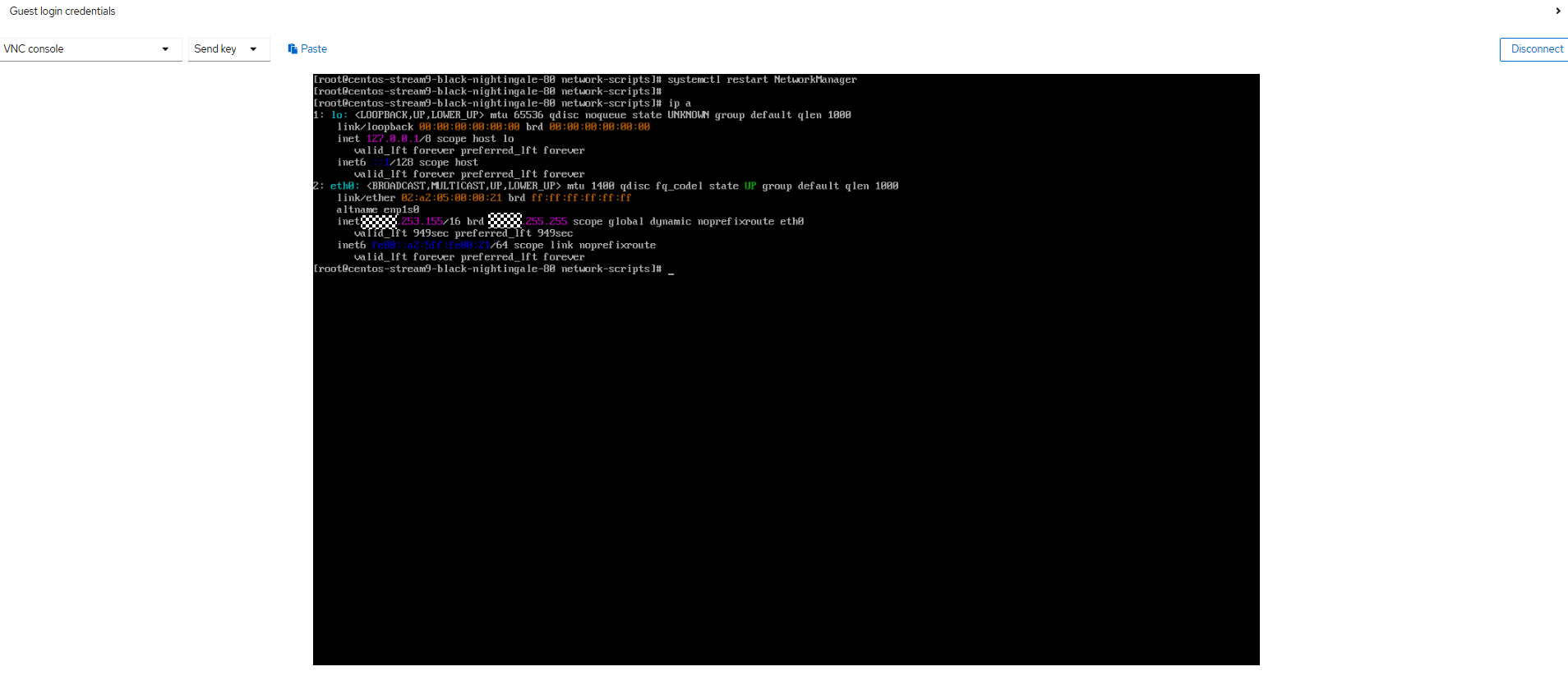
Step 6 Log in to the VM using VNC and run the following command to restart the network service. The VM will be automatically assigned with an IP address.
systemctl restart NetworkManager
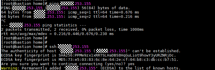
Step 7 Ping the VM on any node that can communicate with the network. The VM can be pinged.
—-End
3.6.5 Performing Live VM Migration
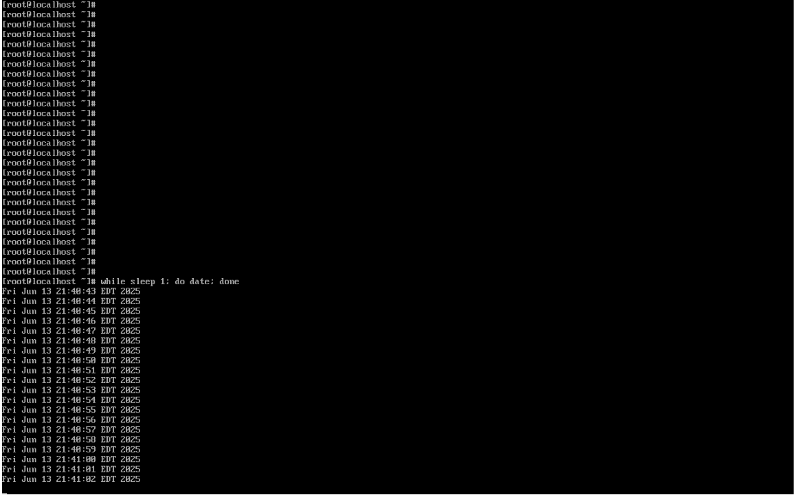
Step 1 Run the following command on the VM to ensure that the VM is running properly:
while sleep 1; do date; done
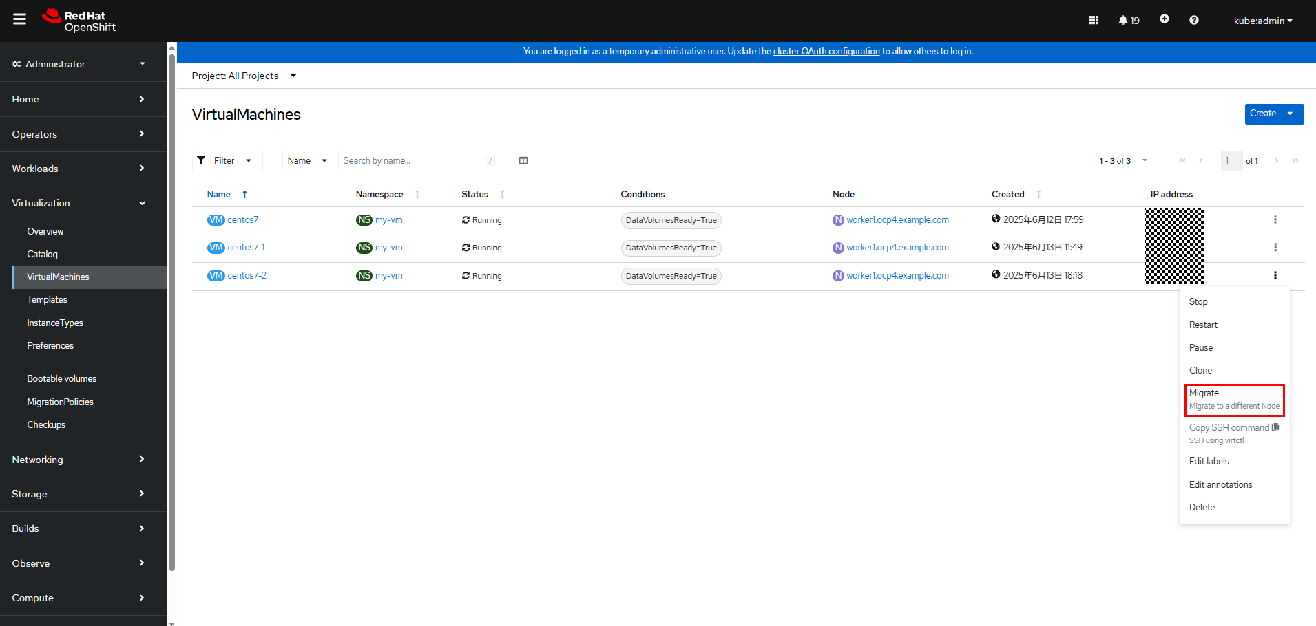
Step 2 Log in to the OpenShift web console and choose Virtualization > VirtualMachines. The VM management page is displayed.
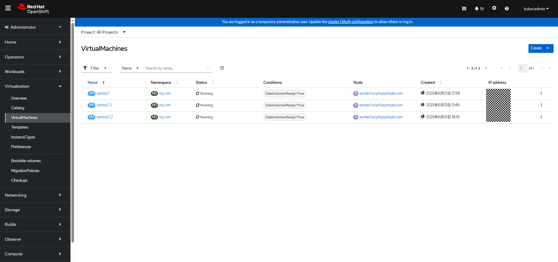
Step 3 Locate the row that contains the VM to be migrated, click

, and then choose Migrate.
Step 4 Wait until the migration is complete.
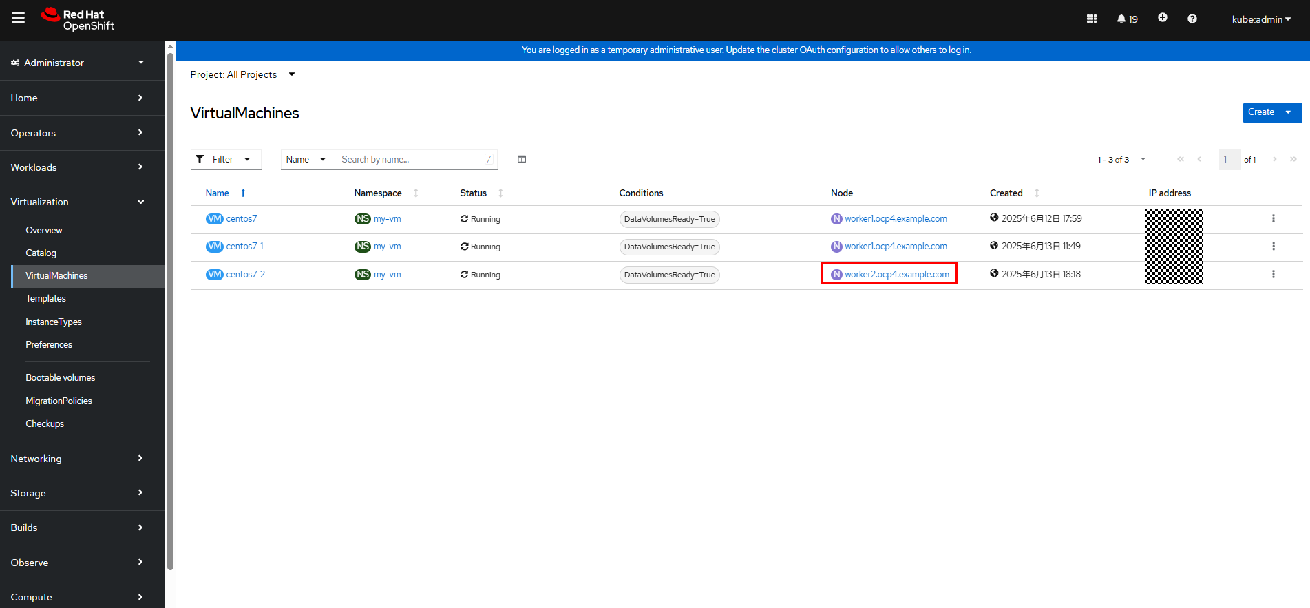
During VM migration, the command line output will not be interrupted. Live VM migration does not affect VM services.

Step 5 Check the VM state in the cluster.
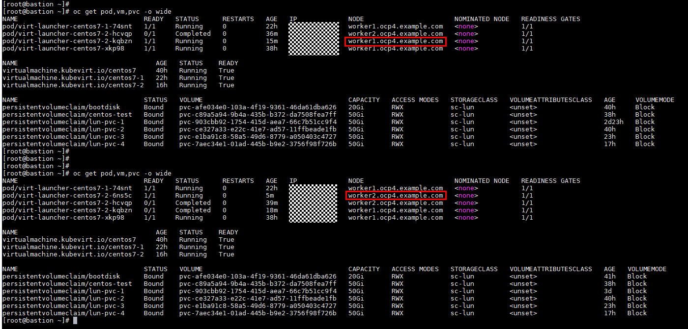
—-End
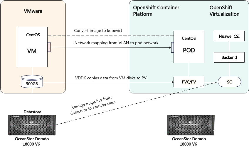
3.6.6 Migrating VMs from vSphere to OpenShift Virtualization
VMs can be migrated from other virtualization platforms to OpenShift Virtualization using the Migration Toolkit for Virtualization (MTV). Install the MTV operator by referring to Installing and configuring the MTV Operator first. After the MTV is installed, migrate VMs by referring to Migrating virtual machines by using the Red Hat OpenShift web console or Migrating virtual machines from the command line. In this example, the former method is used.

The MTV supports concurrent migration of multiple VMs. In this example, only the migration of one VM is verified.
The VMware Virtual Disk Development Kit (VDDK) is not configured for cold migration and the VM migration is slow. In this example, the migration of a VM takes more than two hours.
VDDK is configured for warm migration, and it takes about 15 minutes to migrate a VM. Therefore, if you need to migrate VMs from vSphere to OpenShift Virtualization, you are strongly advised to configure VDDK according to Creating a VDDK image.
The following figure shows the process of migrating a VM from VMware to OpenShift Virtualization.
Figure 3-1 Migration of a VM from VMware to OpenShift Virtualization
3.6.6.1 Cold Migration
Add a VMware vSphere source provider: On the OpenShift web console, choose Migration > Providers for virtualization and click Create Provider to create a VMware vSphere source provider. After the creation is complete, the status is Ready. You can view information about VMs, hosts, and networks on vSphere.
In this example, the parameters for creating a source provider are as follows:
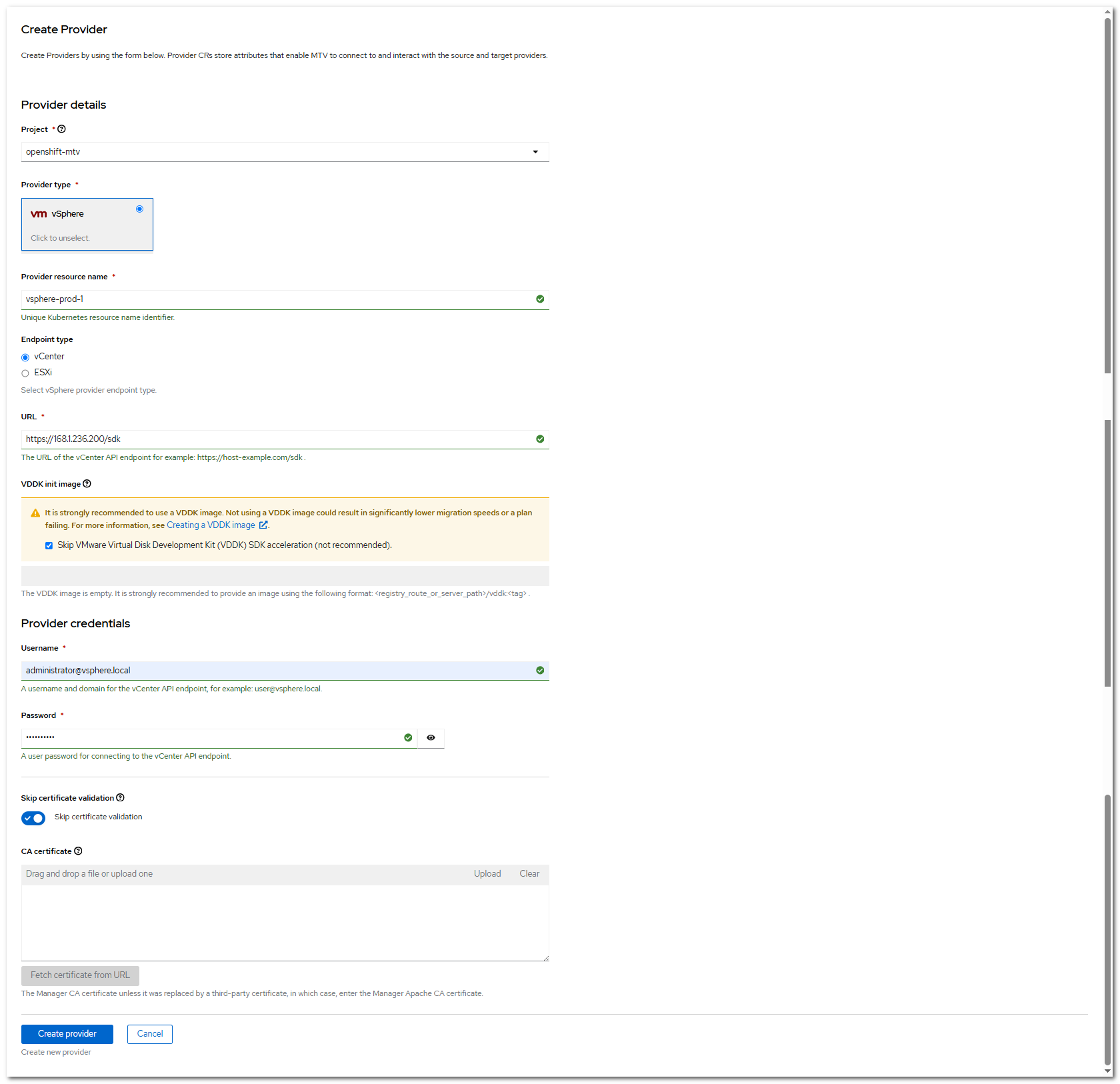
Click Create provider to complete the creation.
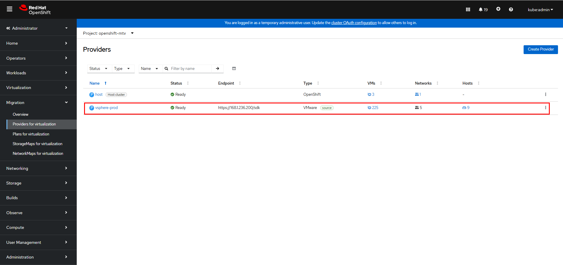
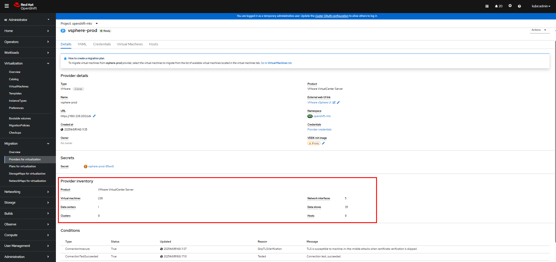
For more information, click vsphere-prod to go to the details page. (vsphere-prod indicates the provider name.)
Step 2 Add an OpenShift Virtualization destination provider: On the OpenShift web console, choose Migration > Providers for virtualization and click Create Provider to create an OpenShift Virtualization destination provider. After the creation is complete, the status is Ready. You can view the number of VMs and networks in the cluster.
In this example, the destination provider parameters are set as follows. You can run the following commands to create a service account bearer token:
oc create sa cluster-admin -n kube-system
oc adm policy add-cluster-role-to-user cluster-admin -z cluster-admin -n kube-system
oc create token cluster-admin -n kube-system
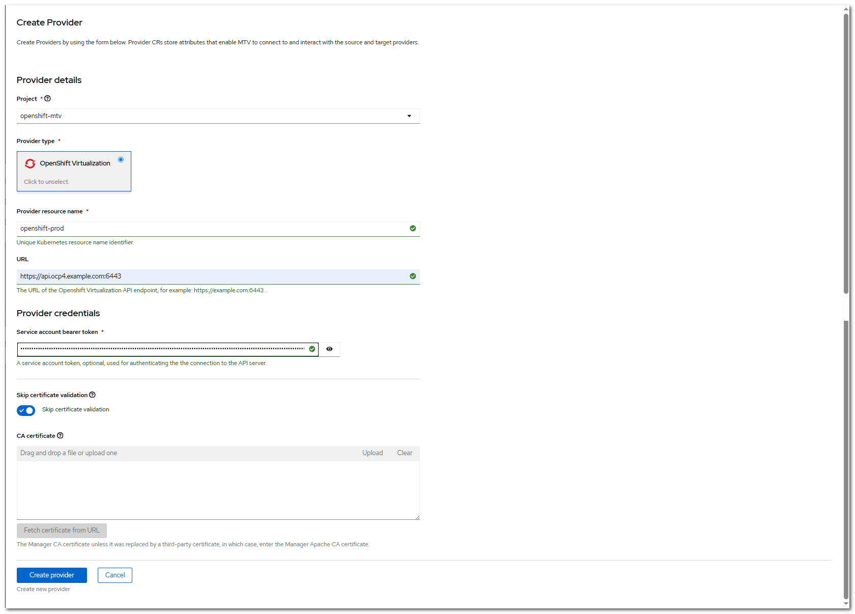
Click Create provider to complete the creation.
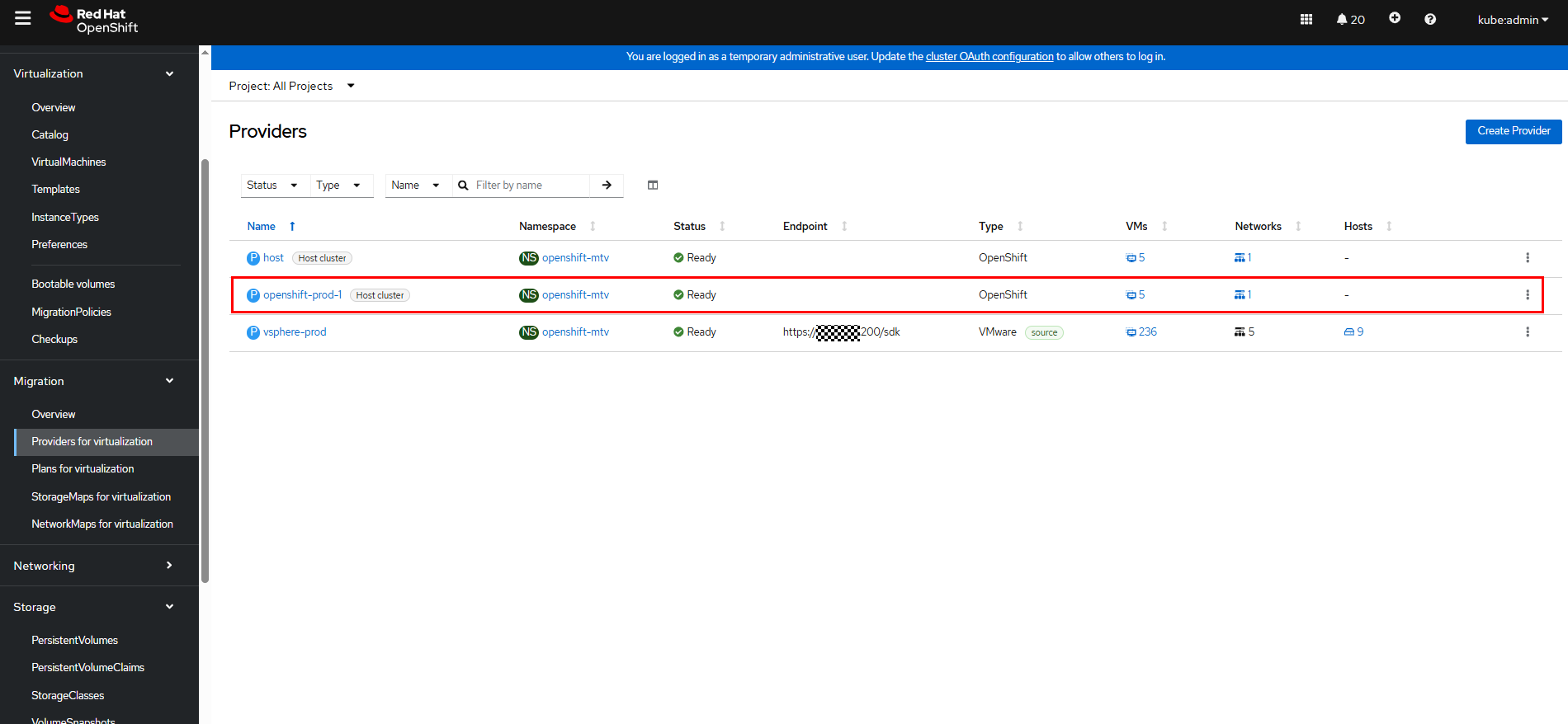
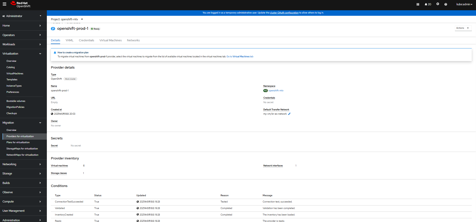
For more information, click openshift-prod-1 to go to the details page. (openshift-prod-1 indicates the provider name.)
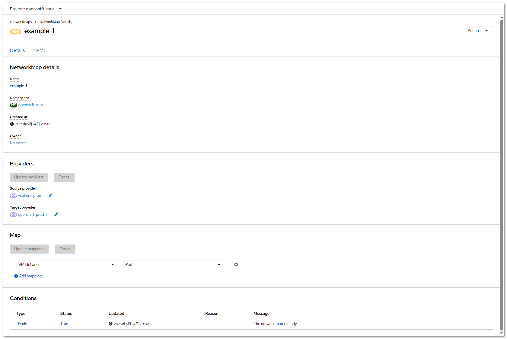
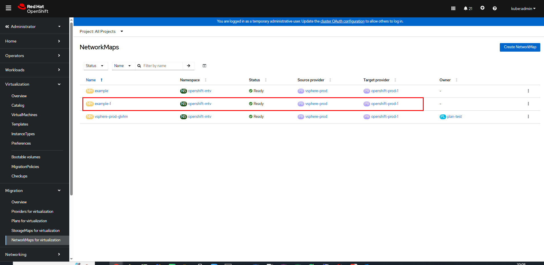
Step 3 Create a network mapping: On the OpenShift web console, choose Migration > NetworkMaps for virtualization.
Click Create NetworkMap. On the Create NetworkMap page that is displayed, modify the information in the YAML.
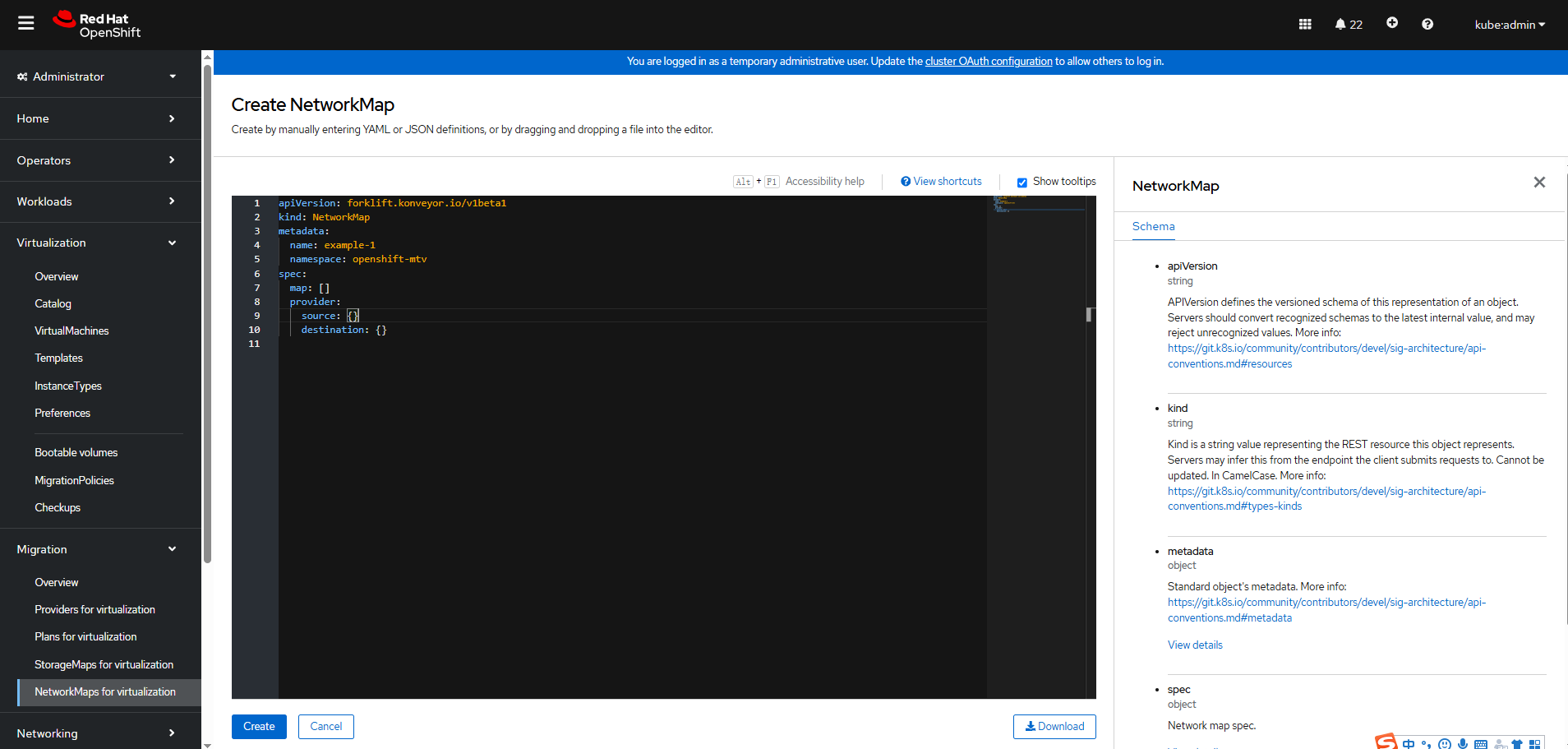
Click Create. On the parameter configuration page, specify Source provider and Target provider, and set Map to create a network map.

In this example, the network of the VMware VM is VM Network, and the network of the OpenShift cluster is Pod.
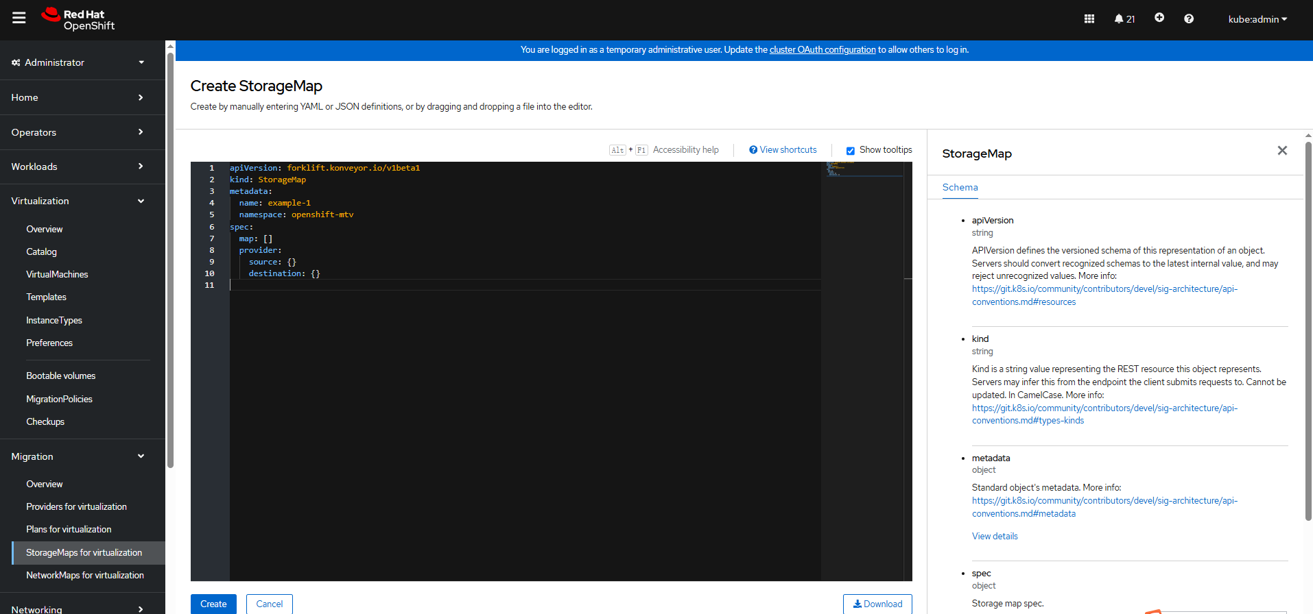
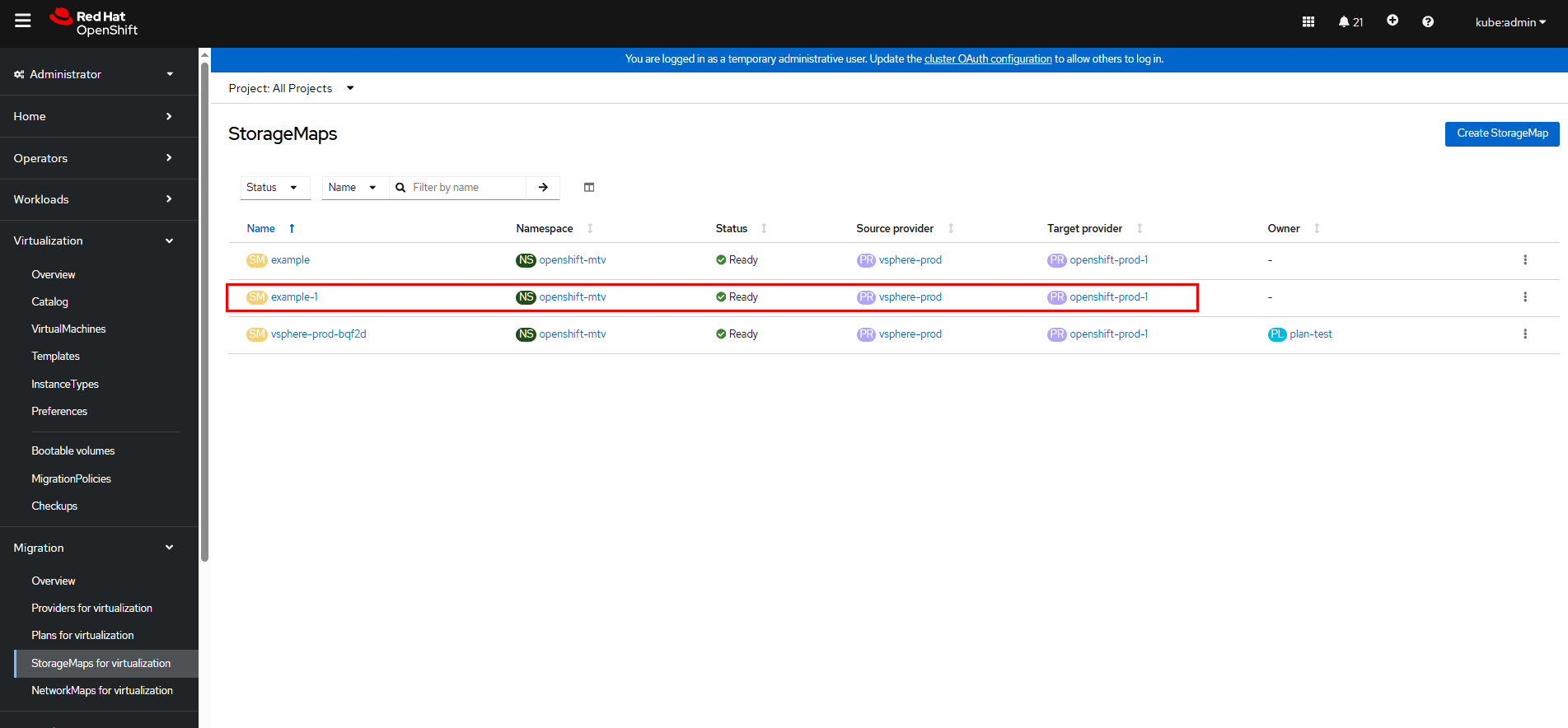
Step 4 Create a storage mapping: On the OpenShift web console, choose Migration > StorageMaps for virtualization.
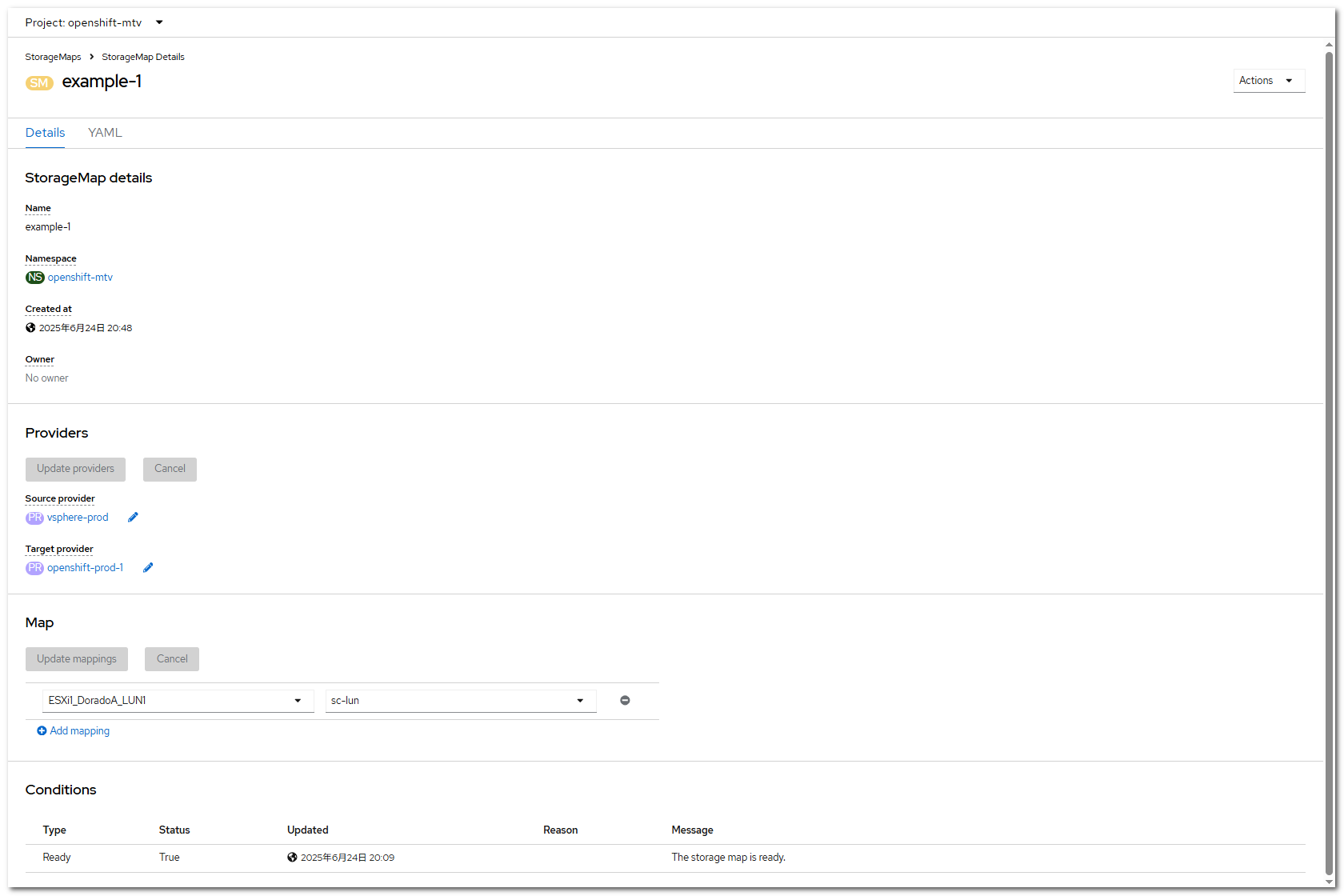
Click Create StorageMap. On the Create StorageMap page that is displayed, modify the information in the YAML.
Click Create. On the parameter configuration page, specify Source provider and Target provider, and configure Datastore and SC of Map to create a storage mapping.

In this example, the datastore of the VM is ESXi1_DoradoA_LUN1, and the SC is sc-lun created in 3.6.2 Creating an SC.
Step 5 Create a migration plan: On the OpenShift web console, choose Migration > Plans for virtualization.
Click Create Plan. On the Select source provider tab page, specify the plan name, select vSphere-prod created in Step 1, and select the VM to be migrated, for example, mjw-test-centos8.
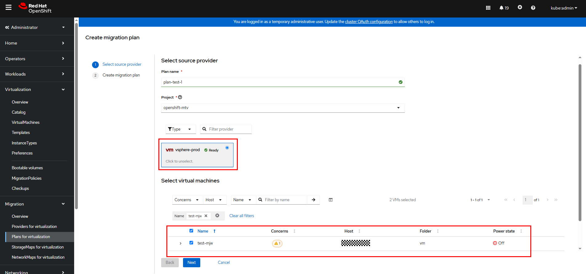
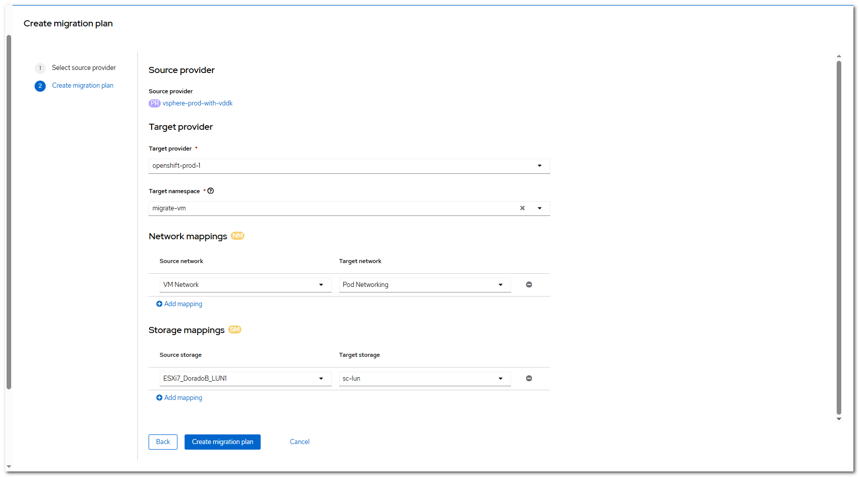
Click Next. The Create migration plan page is displayed. Set the parameters as shown in the following figure.
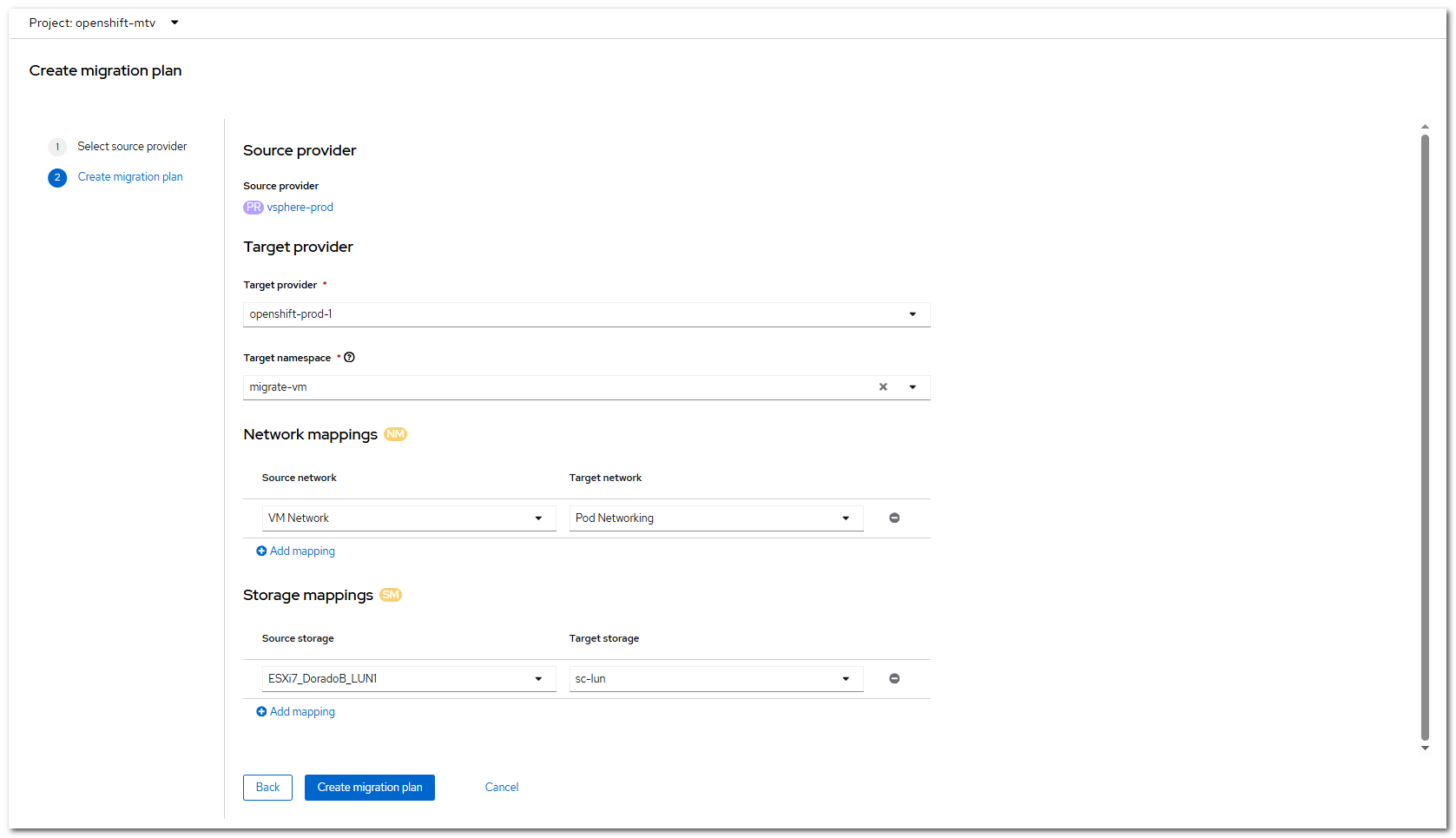
Click Create migration plan to complete the creation.
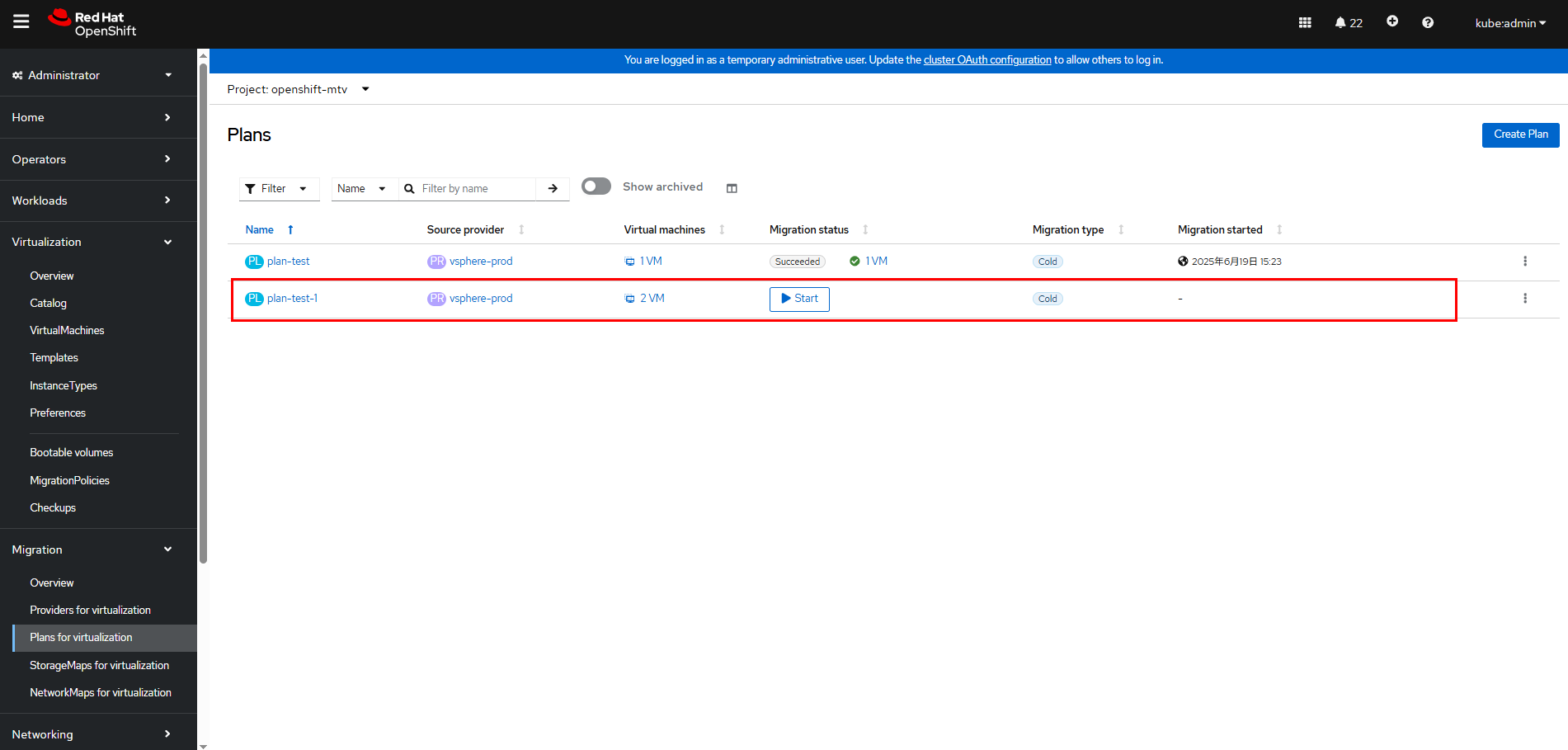
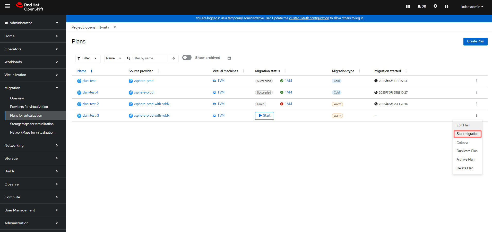
Step 6 On the OpenShift web console, choose Migration > Plans for virtualization,

on the right of the desired migration plan, and choose Start migration.
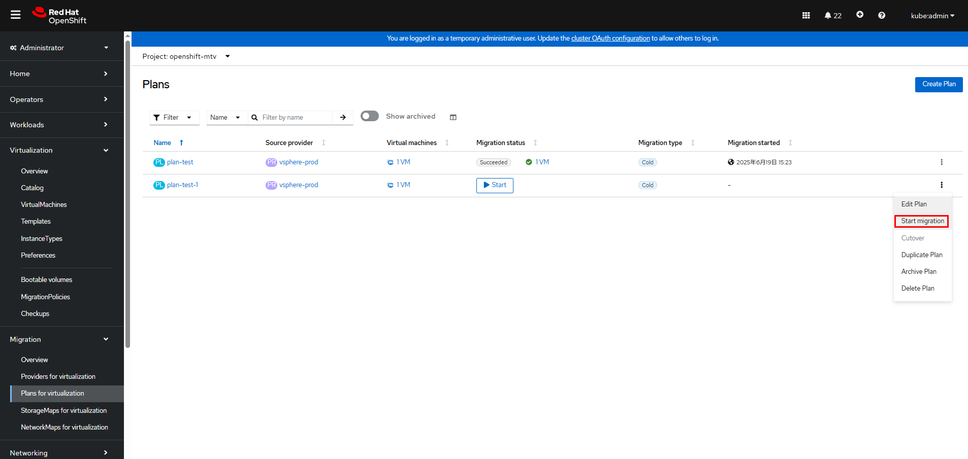

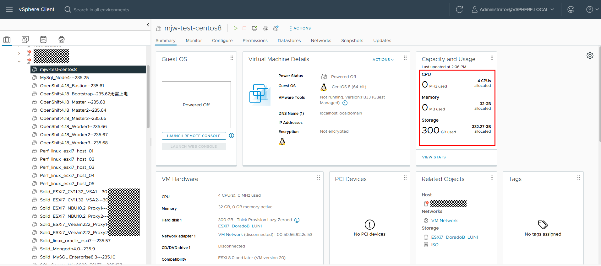
In this example, the name of the VM to be migrated in vSphere is test-mjw-centos8. The VM has 4 CPUs, 32 GB memory, and 300 GB file system size.
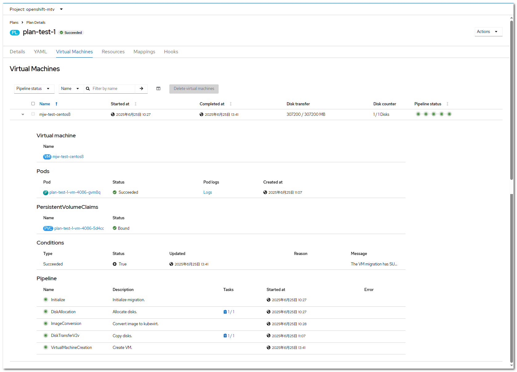
Step 7 On the OpenShift web console, click Migration > Plans for virtualization, click the migration plan name (plan-test-1 in this example), and click the Virtual Machines tab to view the migration progress.
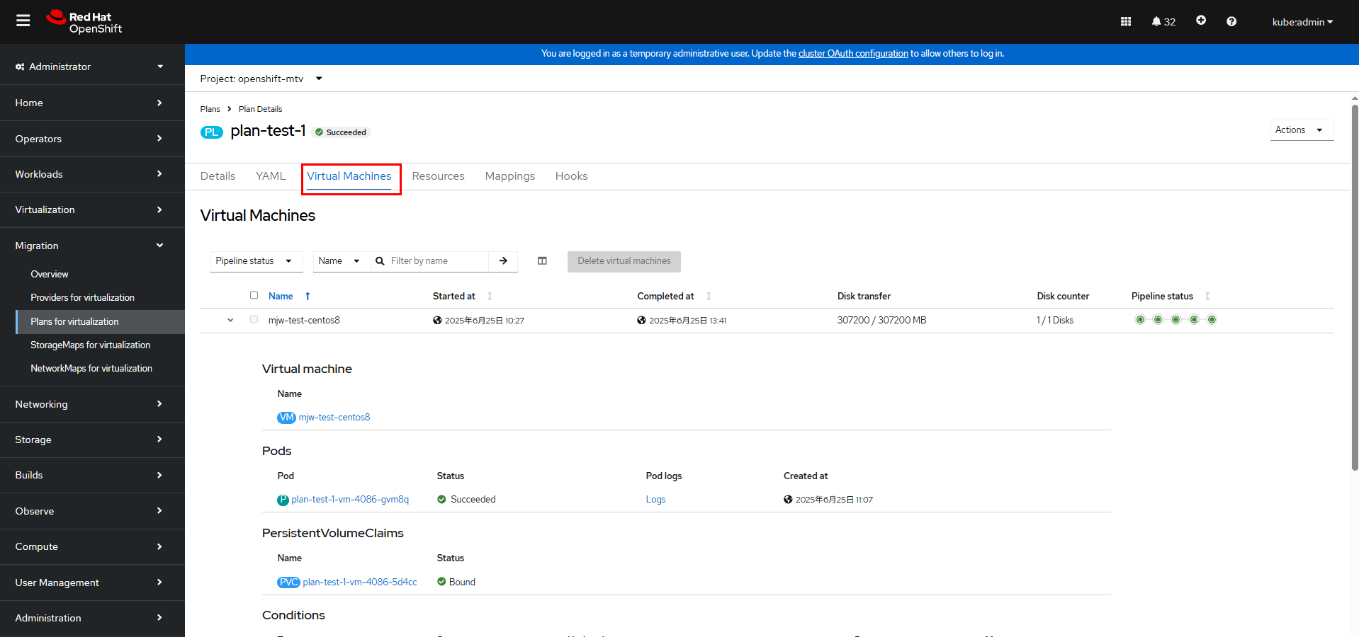
You can also run the following command on the cluster to check the migration status:
oc get pod,vm,pvc -n migrate-vm
Step 8 Wait until the VM migration is complete.
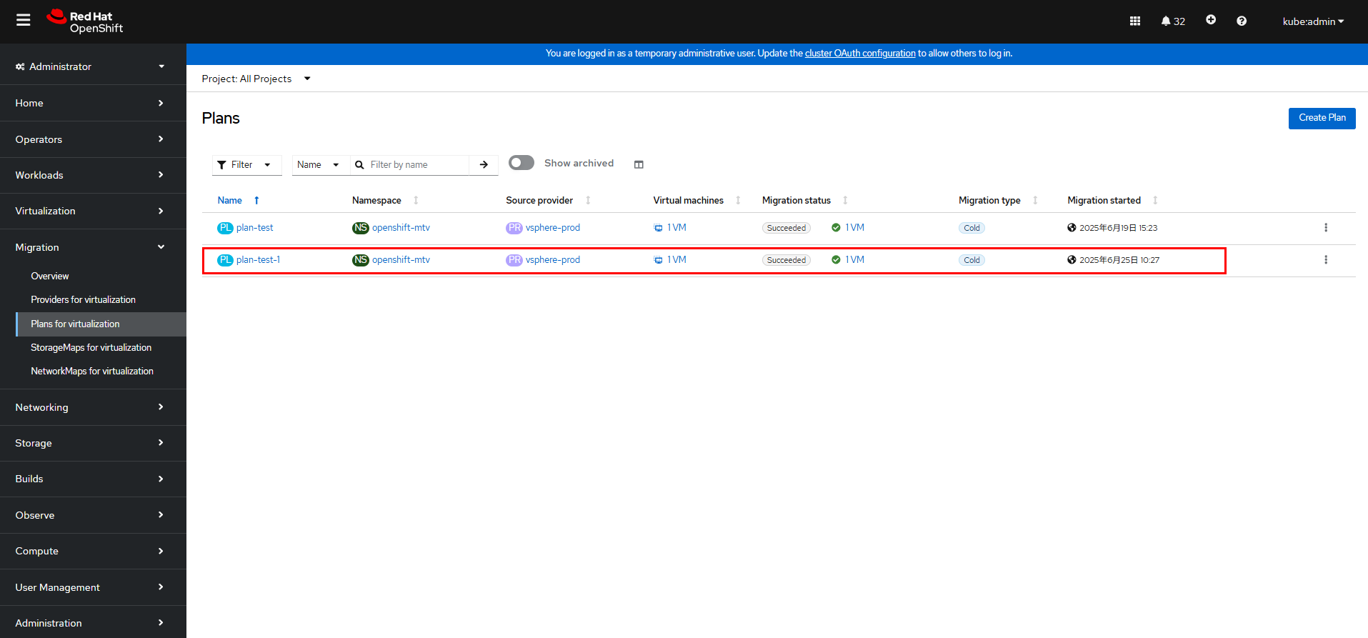
On the OpenShift web console, click Migration > Plans for virtualization, click the migration plan name (plan-test-1 in this example), and click the Virtual Machines tab to view the migration completion time.
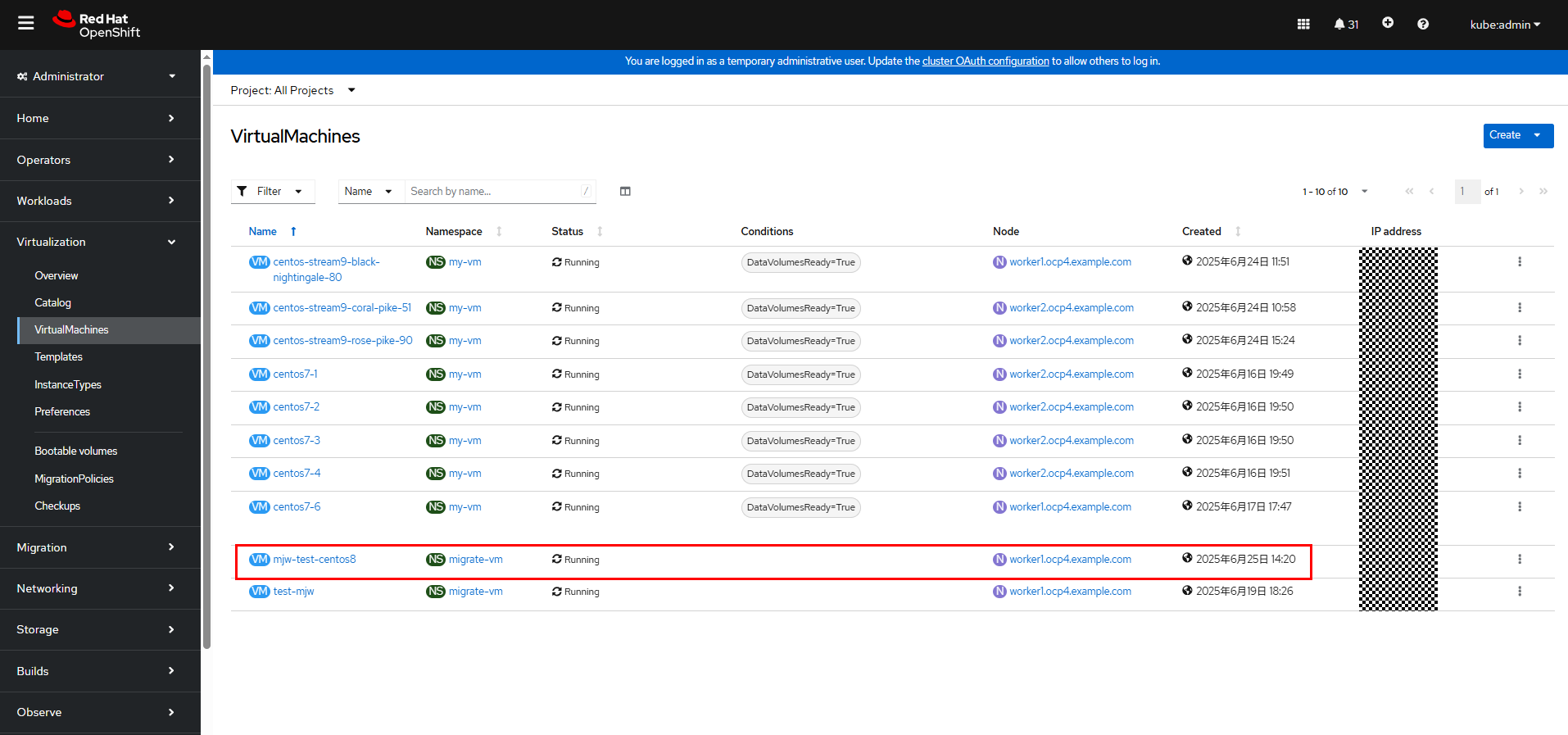
On the OpenShift web console, choose Virtualization > VirtualMachines and check whether the migrated VM is running properly.
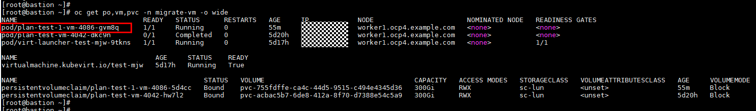
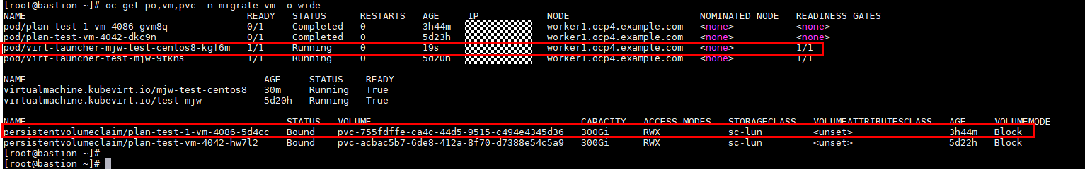
Step 9 On the cluster, run the following command to check the PVC and pod of the migrated VM. After the VM migration is complete, the pod status of the migration plan is Completed, and the status of the VM and the pod corresponding to the VM is Running.
oc get pod,vm,pvc -n migrate-vm -o wide
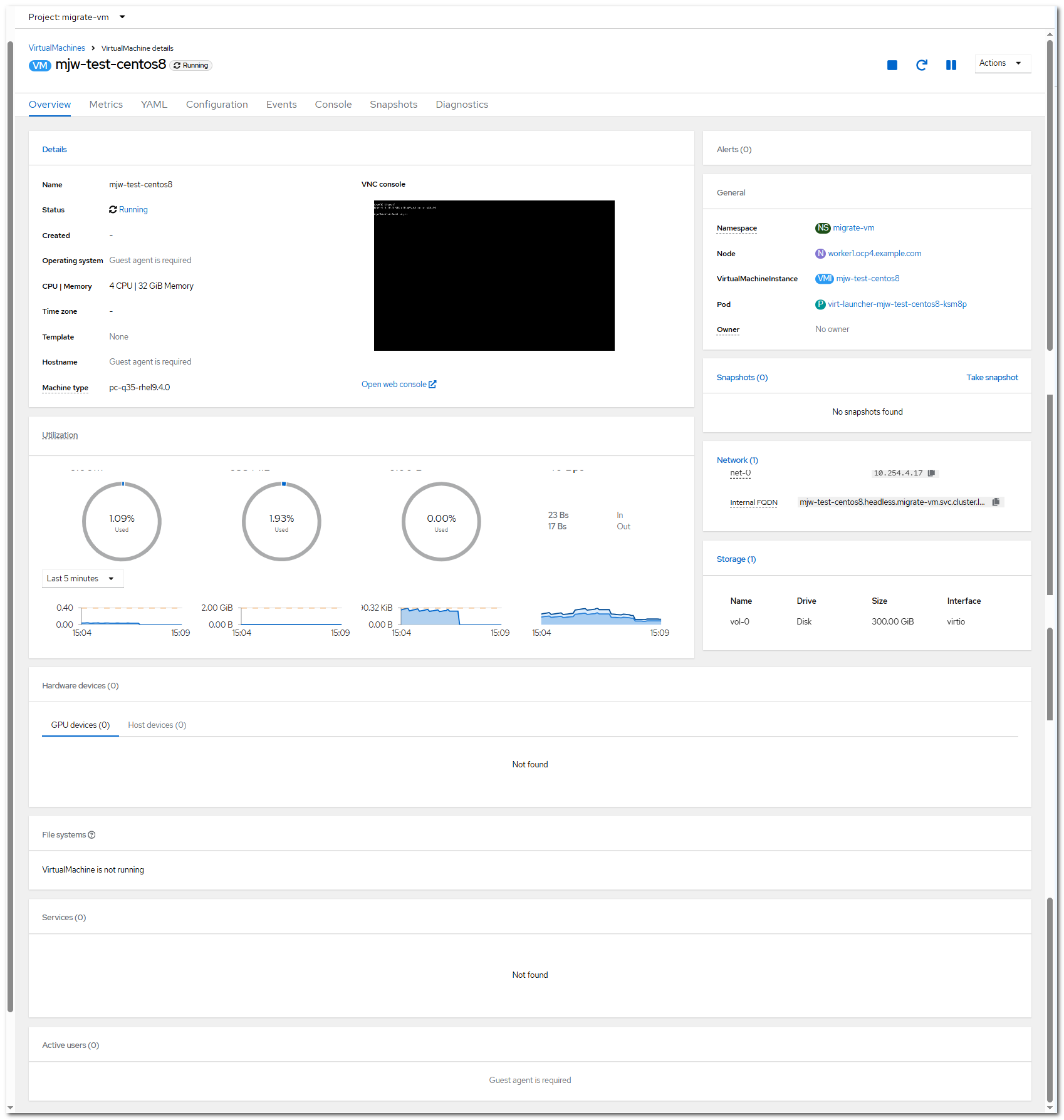
On the OpenShift web console, choose Virtualization > VirtualMachines and click the name of test-mjw-centos8 VM. The VM details page is displayed. You can see that the VM has four CPUs, 32 GB memory, and 300 GB file system size, which are the same as those on vSphere.
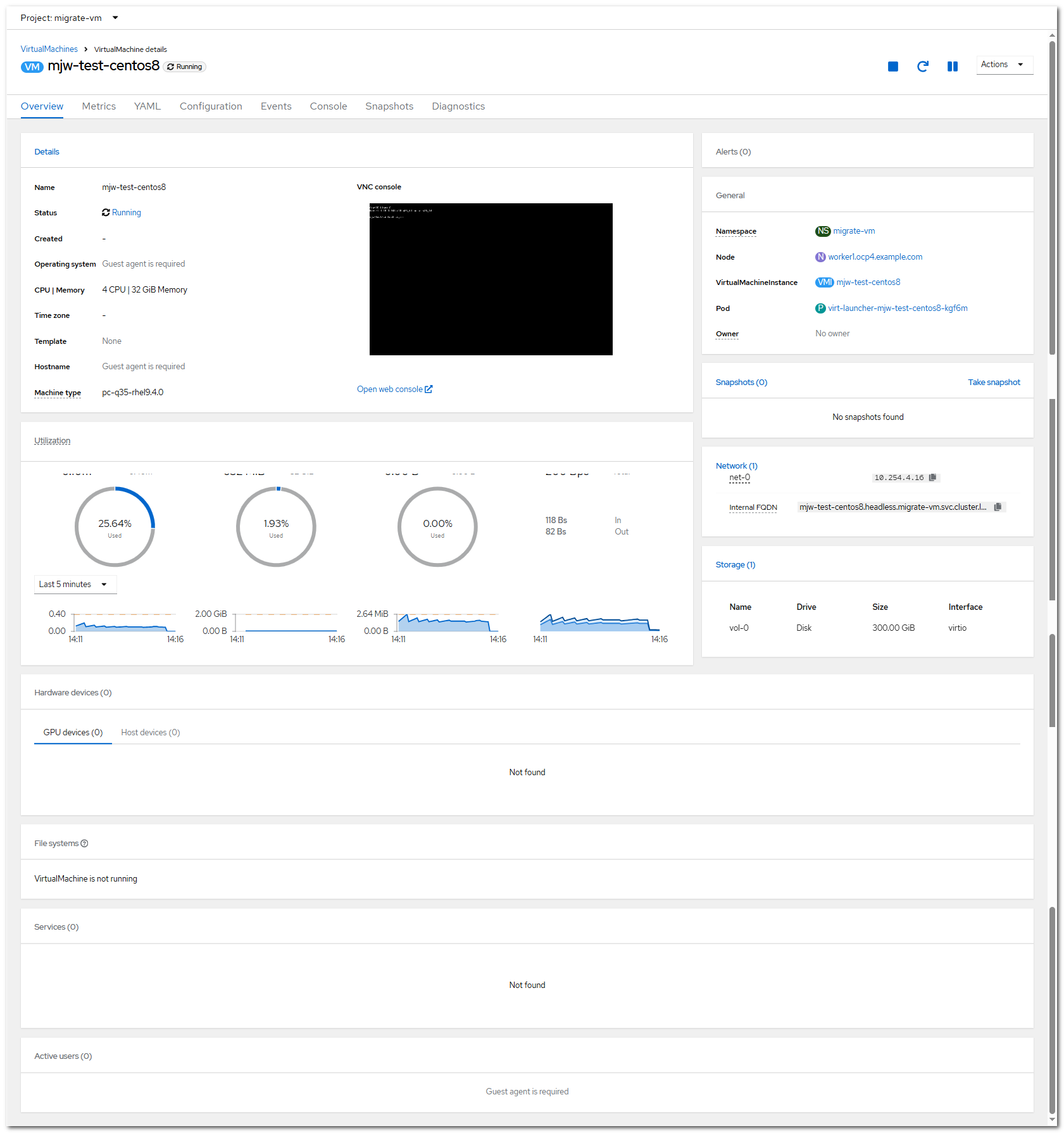
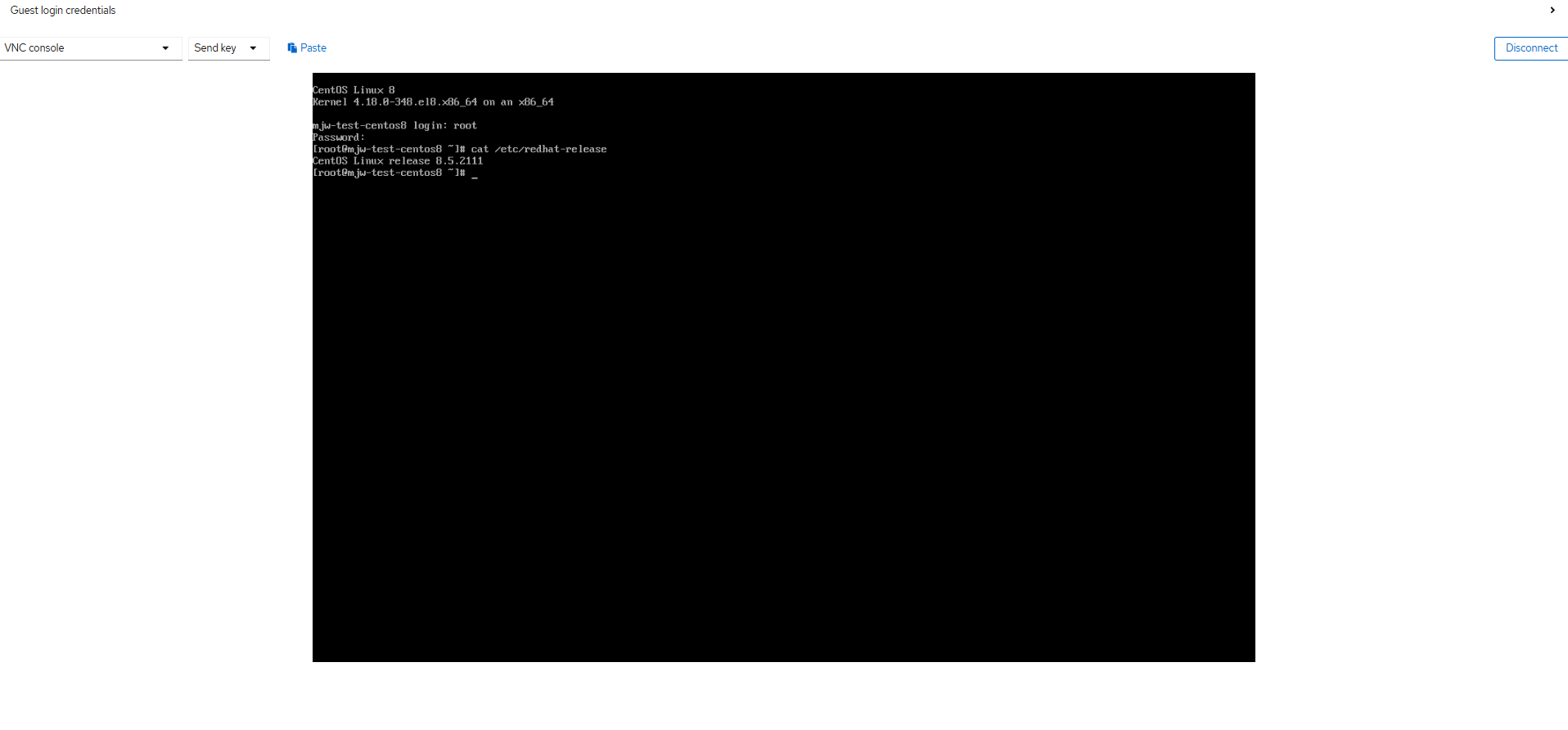
Click Open web console to go to the VNC page. Log in to the VM using the OS username and password. The VM can be accessed.
—-End
3.6.6.2 Warm Migration
Step 1 On the OpenShift web console, choose Migration > Providers for virtualization and click Create Provider to complete the configuration of a provider with VDDK.
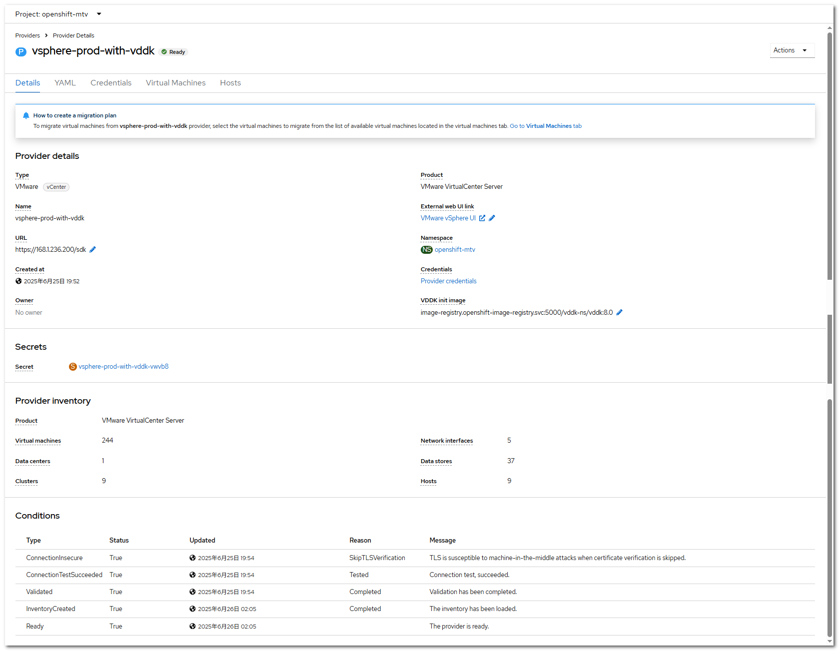

For details about how to configure VDDK, see Creating a VDDK image.
Step 2 On the OpenShift web console, choose Migration > Plans for virtualization and click Create Plan to create a migration plan.
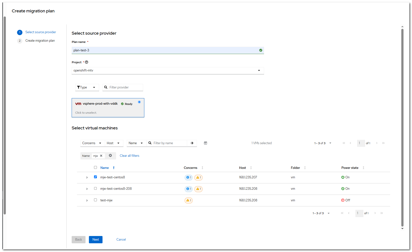
Click Next.
Click Create migrate plan and set Migration type to warm.
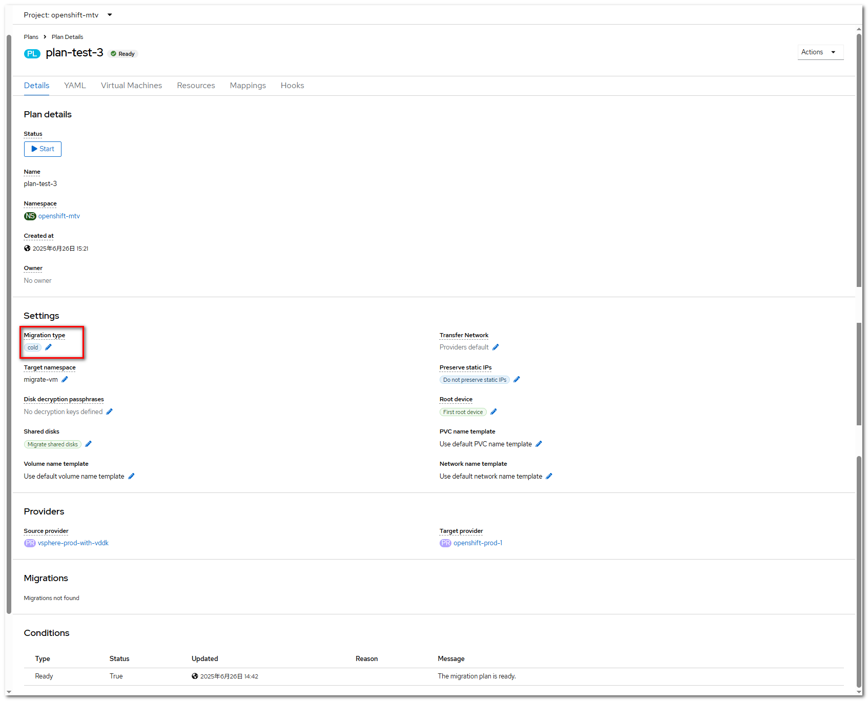
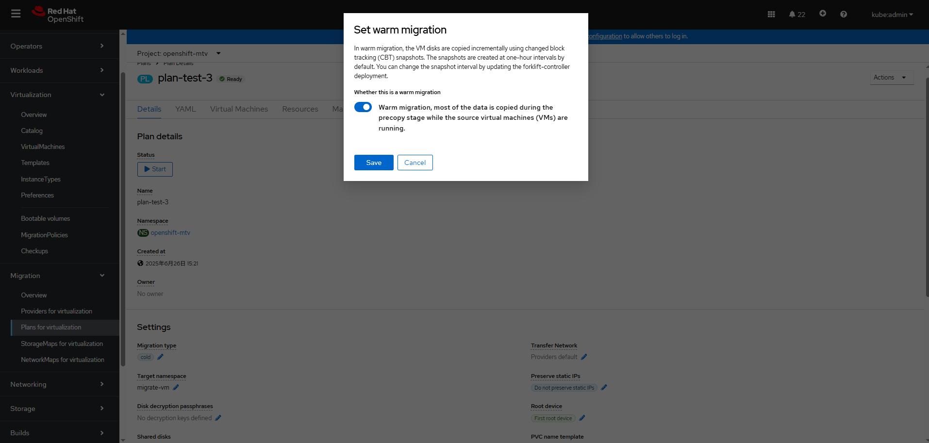

When you create a warm migration plan, the system may display a message indicating that changed block tracking (CBT) is not configured. You can configure CBT by referring to the following description. CBT is a VMware vSphere feature that transmits only the data blocks that have been changed since the last backup, increasing the backup efficiency and rate.
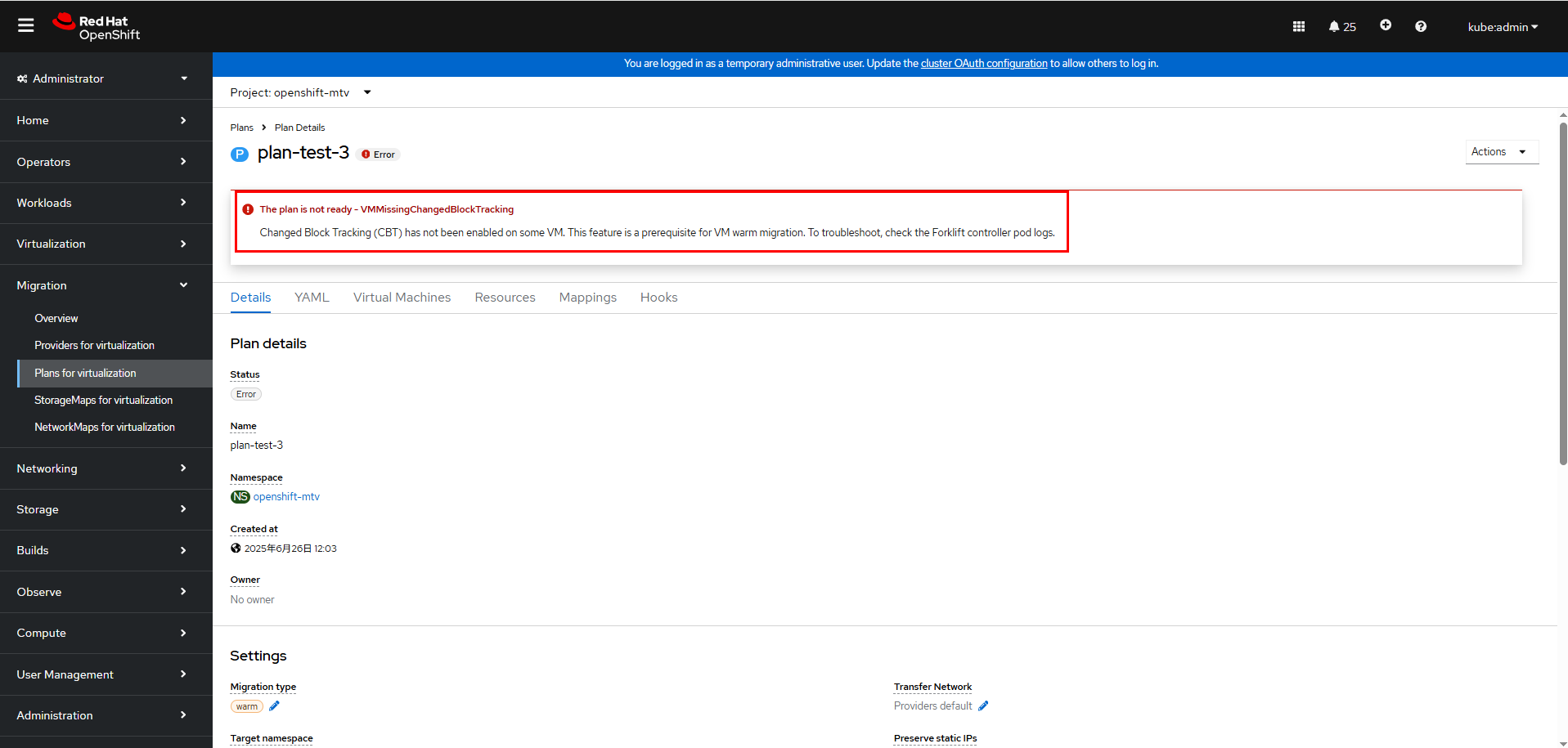
To configure CBT for VMs:
- Log in to vCenter: Access your vSphere Web Client and log in to the vCenter Server.
- Select the specific VM: In the host and cluster view, select the VM for which you want to enable CBT.
- Power off the VM. A VM must be powered off before its configuration is modified. Right-click the VM and choose Power > Power Off.
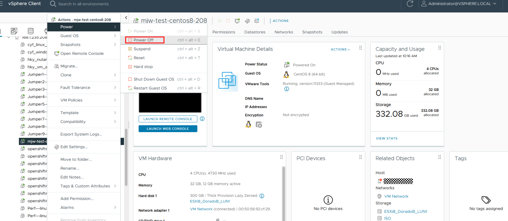
- Edit the VM settings: Select Edit Settings.
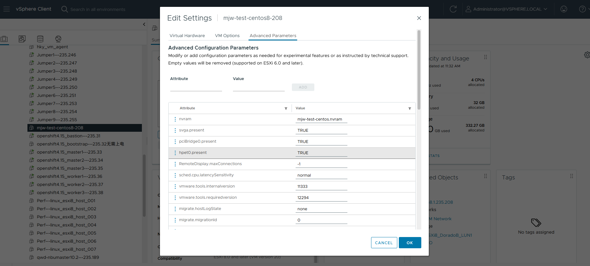
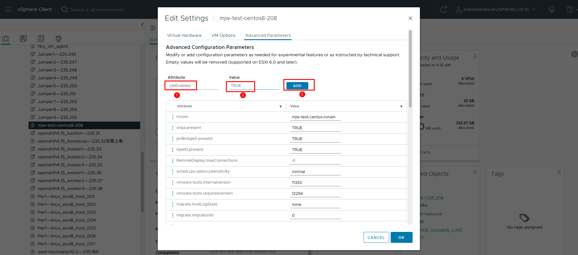
- Add the CBT parameter.
On the VM Options tab page, click Advanced Parameters to edit the configuration.
Enter ctkEnabled and set it to TRUE.
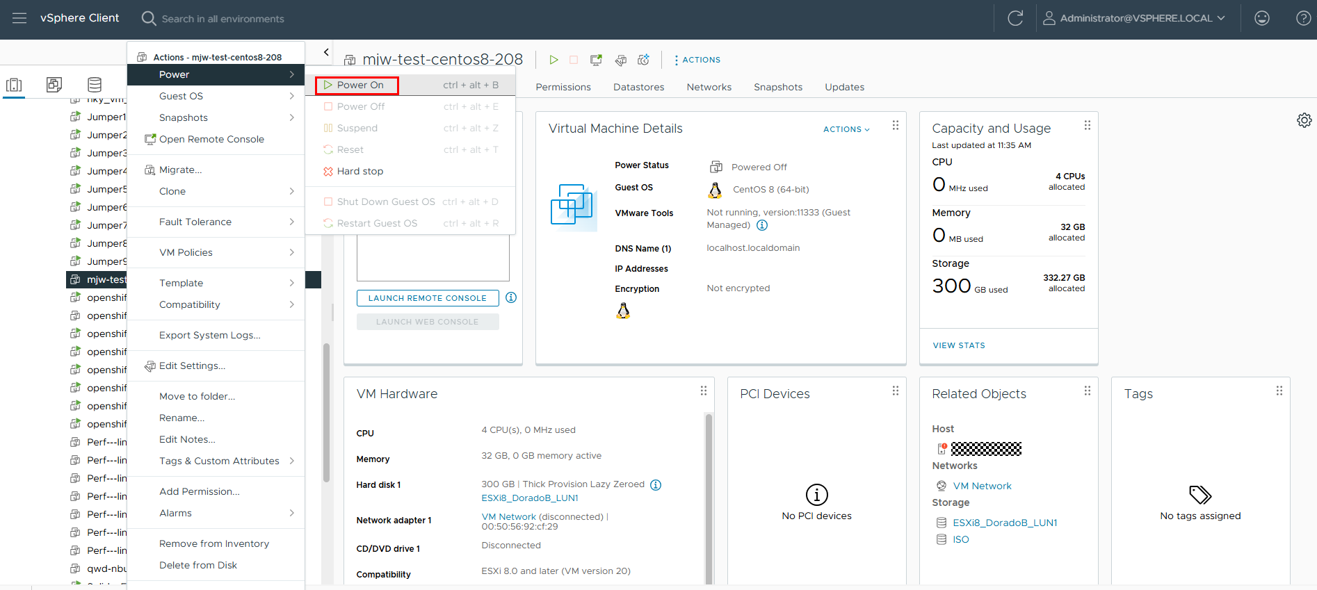
- Restart the VM.
Save the settings and close the window. Restart the VM for the new settings to take effect.
After CBT is enabled for the VM, the migration plan status changes to Start.

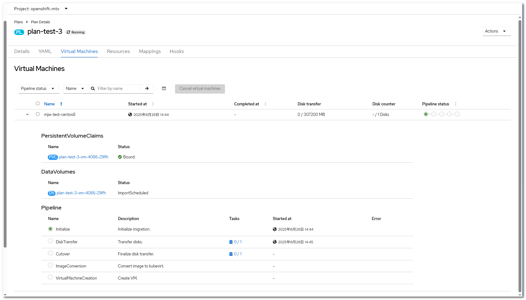
Step 3 On the OpenShift web console, click Migration > Plans for virtualization to start the migration.
Click the migration plan name, for example, plan-test-3, to go to the migration plan details page. Click the Virtual Machines tab to view the migration progress.
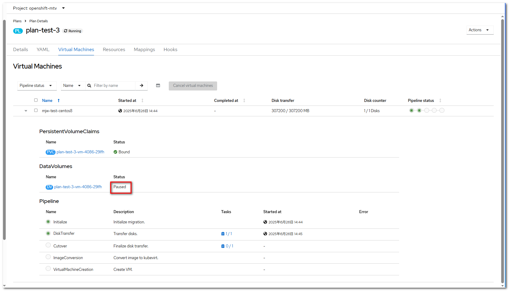
Step 4 After a period of time, the disk transmission is complete, and the migration process enters the cutover state. At this time, the DataVolume is in the Paused state. Return to the migration plan and click Cutover to continue the migration.
Step 5 On the OpenShift web console, choose Migration > Plans for virtualization and click Cutover.
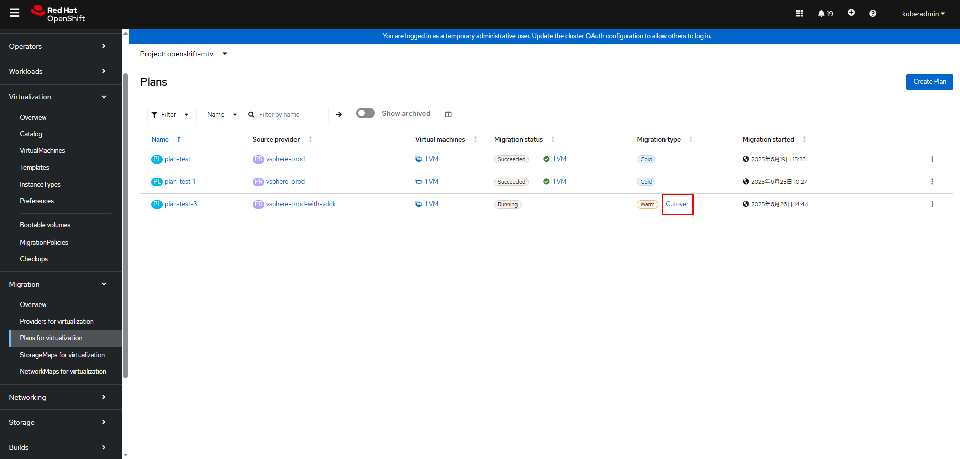
The current time is displayed in the Cutover dialog box. If you want to perform the cutover at a later time, change the current time to a future time. If you want to perform the cutover immediately, click Set Cutover.
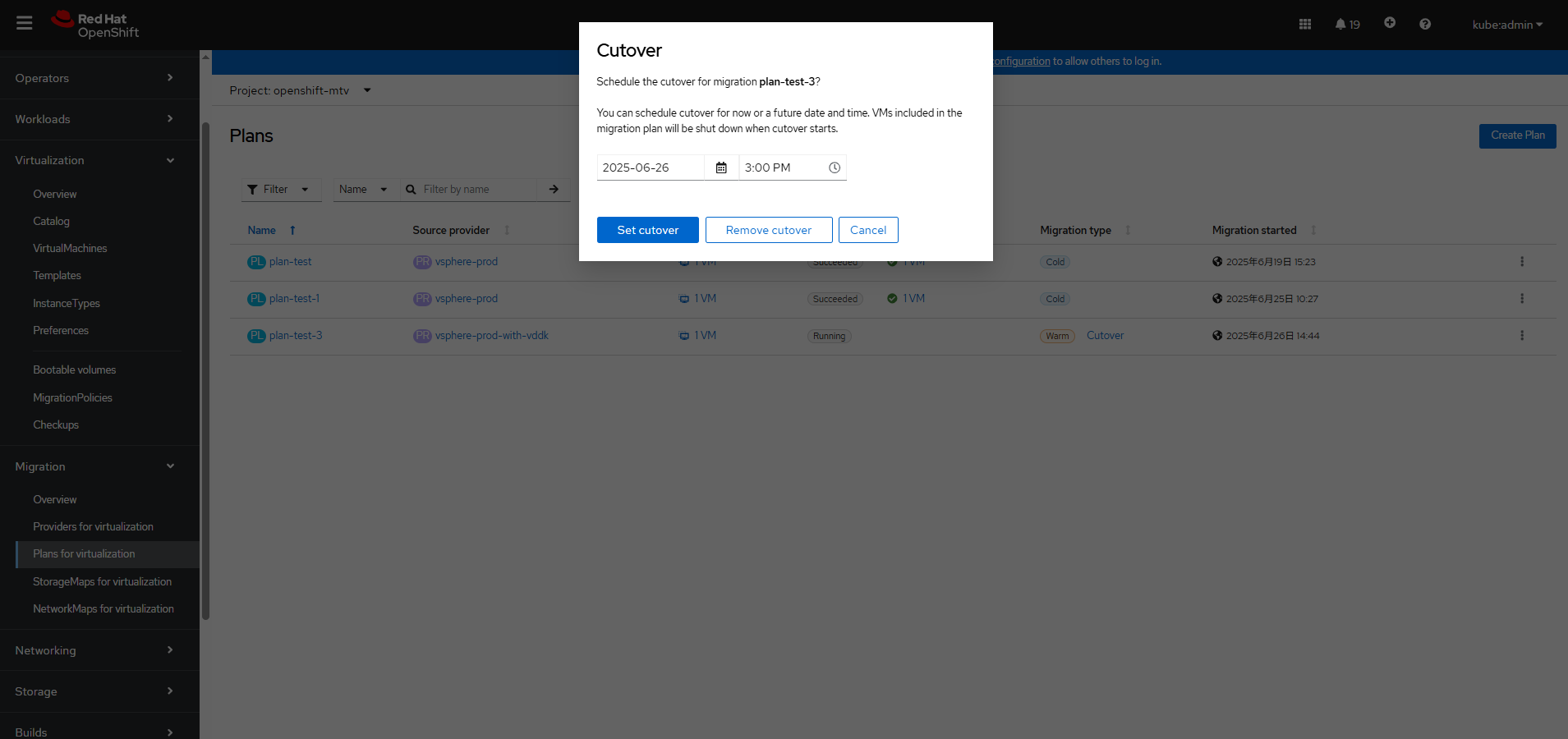
After the cutover phase starts, the DataVolume status changes from Paused to ImportScheduled and then to ImportInProgress within several seconds. After the cutover phase is complete, the DataVolume status changes to Succeeded.
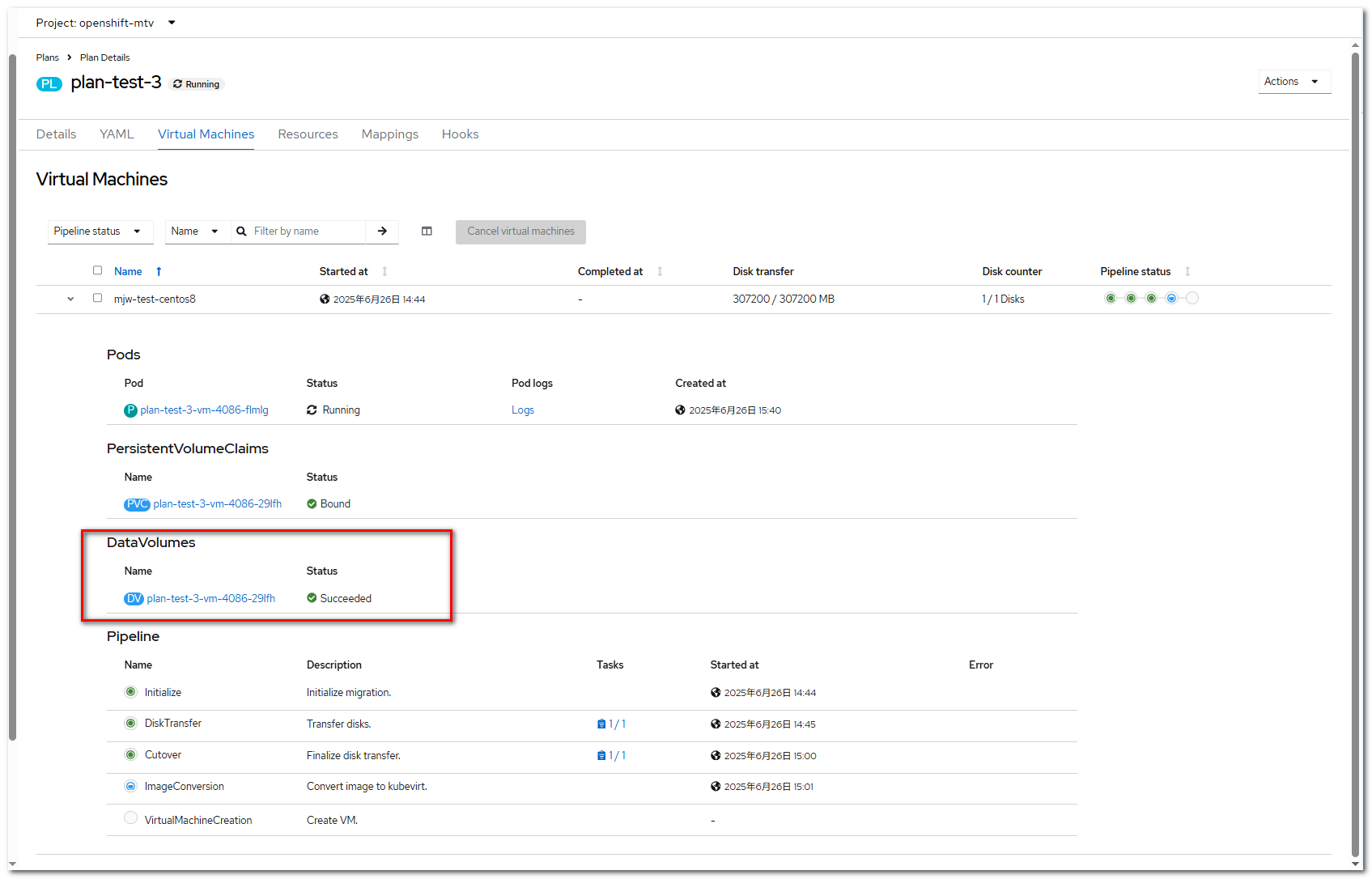
The migration plan will continue with ImageConversion and finally VirtualMachineCreation.
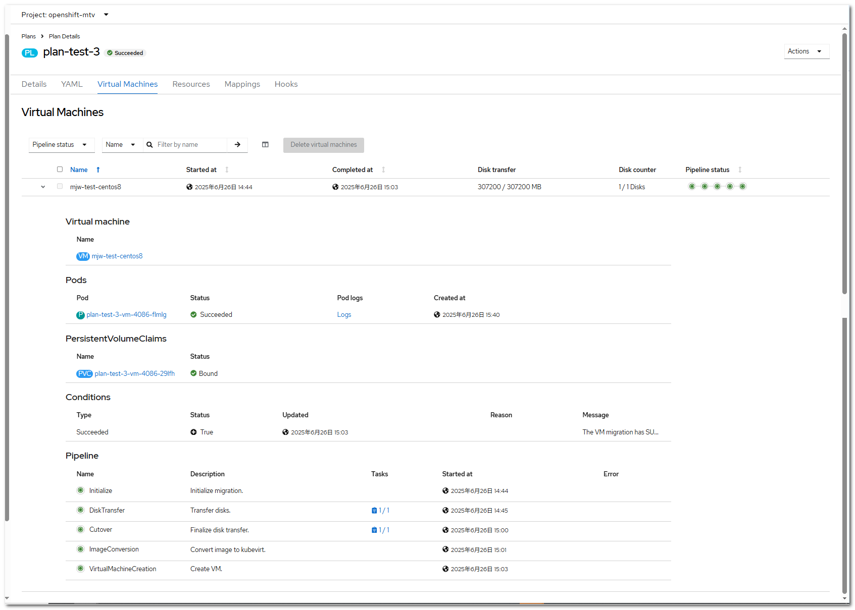
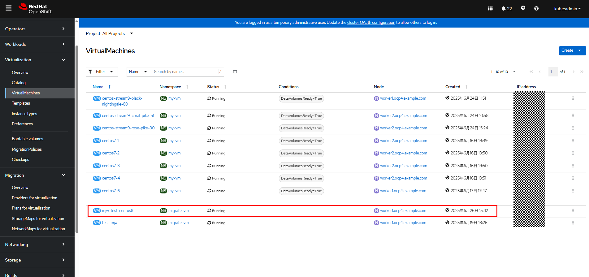
Step 6 After the migration process is complete, the VM will be in the Running state on OpenShift Virtualization.
Go to the VM details page. The configurations such as CPU and memory are the same as those of the original VM.
—-End
3.6.7 Deleting a VM
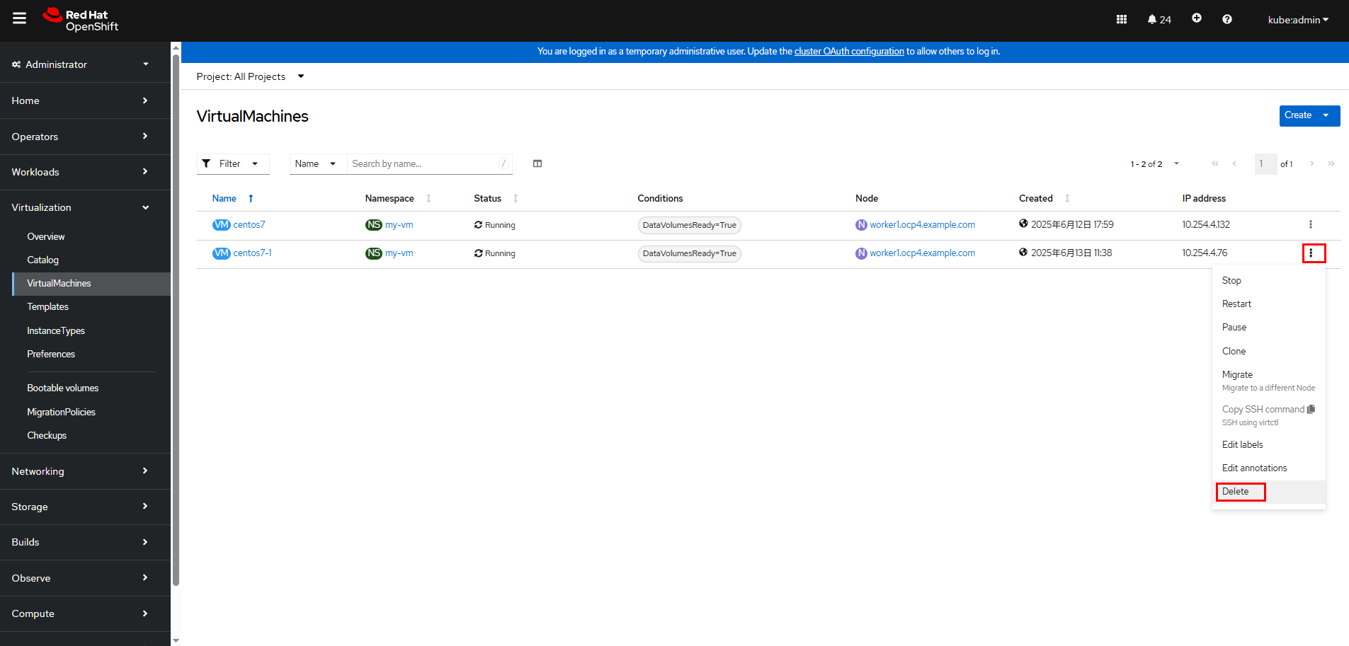
Step 1 On the web page, choose Virtualization > VirtualMachines.
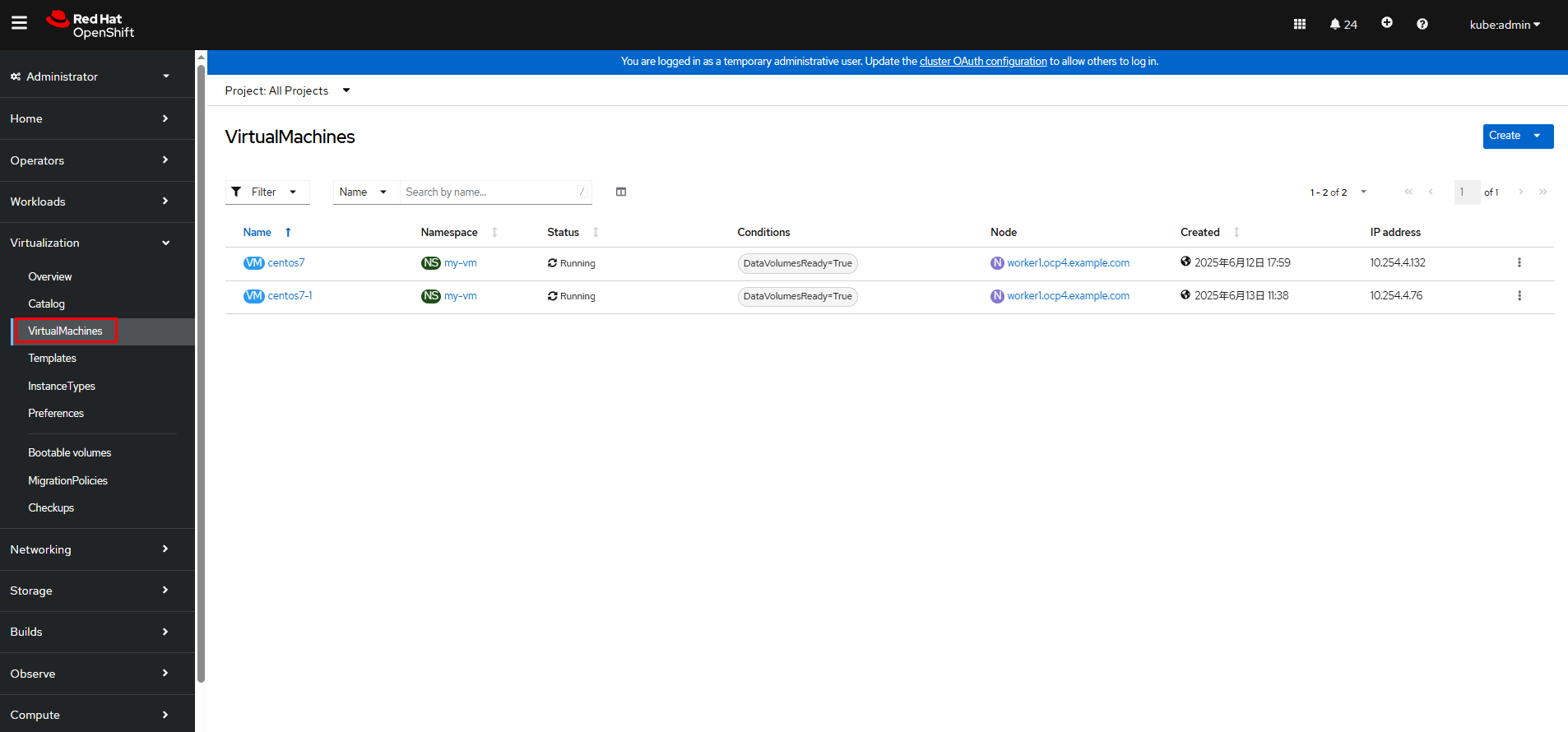
Click

on the right of the VM to be deleted and choose Delete.
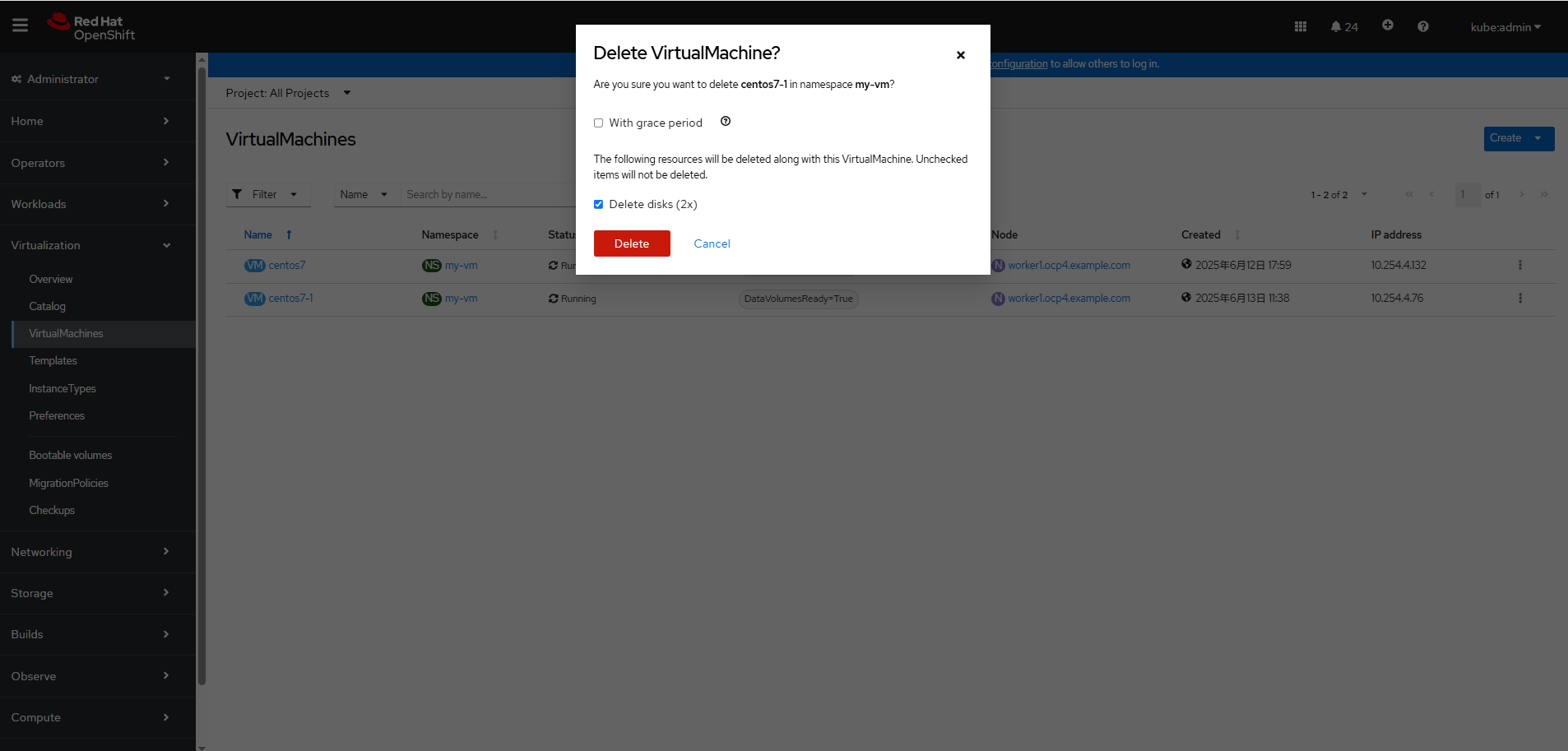
Confirm the deletion.
—-End
3.6.8 Verifying the Operation Efficiency
Most users are concerned about the efficiency of creating and deleting VMs and PVCs in batches in the OCPV environment. The following table lists the verification result.
Table 3-1 Verification result of batch creation and deletion of PVCs and VMs on OpenShift Container Platform 4.16
Category | Creating 100 PVCs in a Batch | Deleting 100 PVCs in a Batch | Creating 30 VMs in a Batch | Deleting 30 VMs in a Batch |
|---|---|---|---|---|
|
|
|
|
|

- The time required for creating PVCs in a batch by CSI is measured after all PVCs are in the Bound state and that required for deleting PVCs in a batch is measured after all PVs are deleted.
- The time required for creating and deleting VMs in a batch is measured by running the virtctl command on the CLI.
- The time required varies depending on the host performance configuration in each cluster. The data is for reference only.
4 Summary
This solution verifies the integration of Huawei OceanStor Dorado storage with OpenShift Container Platform Virtualization (OCPV) using Huawei CSI and tests related functions. The details are as follows:
1. CSI storage function verification
- Dynamic volume management: This solution verifies that PVCs can be dynamically created through StorageClasses and bound to PVs to ensure that storage resources are allocated on demand.
2. OpenShift Virtualization function verification
- VM creation and deletion: The complete process of creating and deleting VMs on OCPV based on the KubeVirt technology is verified to ensure proper VM lifecycle management.
- Live VM migration: It is verified that VMs can be migrated between different nodes without service interruption to ensure high service availability.
- Cross-platform VM migration: It is verified that VMs can be migrated from vSphere to OpenShift Virtualization, achieving seamless migration between heterogeneous virtualization platforms. The VM configuration, disk data, network policies, and metadata are completely retained. After the migration, the VMs run properly on the target platform, ensuring service continuity.
3. Operation efficiency verification
- Based on Huawei OceanStor Dorado, Huawei CSI can quickly complete dynamic provisioning and deletion of PVCs and quickly create and delete VMs through KubeVirt
Conclusion
This solution successfully verifies the integration of storage with OCPV using Huawei CSI. In addition, OpenShift Virtualization supports full-lifecycle management and live migration of VMs, meeting enterprise-class containerization and virtualization requirements.
5 Acronyms
Acronym | Description |
|---|---|
|
|
|
|
|
|
|
|
|
|
|
|
6 Attachments
6.1 backend_fc.yaml
storage: « oceanstor-san »
name: « fc-backend-113 »
namespace: « huawei-csi »
urls:
– « https://xx.xx.xx.xx:8088 »
pools:
– « StoragePool001 »
parameters:
protocol: « fc »
maxClientThreads: « 30 »
6.2 sc-fc.yaml
kind: StorageClass
apiVersion: storage.k8s.io/v1
metadata:
name: sc-lun
provisioner: csi.huawei.com
allowVolumeExpansion: true
parameters:
backend: « fc-backend-113 »
pool: « StoragePool001 »
volumeType: lun
allocType: thin
6.3 pvc.yaml
kind: PersistentVolumeClaim
apiVersion: v1
metadata:
name: lun-pvc
spec:
accessModes:
– ReadWriteMany
storageClassName: sc-lun
volumeMode: Block
resources:
requests:
storage: 10Gi
6.4 pod-vdbench-1.yaml
apiVersion: apps/v1
kind: Deployment
metadata:
name: pod-vdbench-1
namespace: test
spec:
replicas: 1
selector:
matchLabels:
app: vdbench-normalapp
template:
metadata:
labels:
app: vdbench-normalapp
spec:
#nodeName: host01
containers:
– name: vdbench-normalapp
image: registry.example.com:8443/tool/centos:7.6-vdbench
command:
– bash
– -c
– sleep 5000000000
volumeMounts:
– name: mypv
mountPath: /opt
volumes:
– name: mypv
persistentVolumeClaim:
claimName: lun-pvc
6.5 create_vm.yaml
apiVersion: kubevirt.io/v1
kind: VirtualMachine
metadata:
name: centos7
namespace: my-vm
spec:
running: false
template:
metadata:
annotations:
vm.kubevirt.io/flavor: small
vm.kubevirt.io/os: centos7
vm.kubevirt.io/workload: server
creationTimestamp: null
labels:
kubevirt.io/domain: centos
kubevirt.io/size: small
spec:
domain:
cpu:
cores: 1
sockets: 1
threads: 1
model: « Nehalem »
devices:
disks:
– disk:
bus: virtio
name: boot-disk
– disk:
bus: virtio
name: data-disk-1
– disk:
bus: virtio
name: cloudinitdisk
interfaces:
– macAddress: ’02:83:e3:00:4D:03′
masquerade: {}
model: virtio
name: default
networkInterfaceMultiqueue: true
rng: {}
machine:
type: pc-q35-rhel8.6.0
resources:
requests:
memory: 2Gi
evictionStrategy: LiveMigrate
networks:
– name: default
pod: {}
terminationGracePeriodSeconds: 180
volumes:
– dataVolume:
name: bootdisk
name: boot-disk
– dataVolume:
name: lun-pvc-2
name: data-disk-1
– cloudInitNoCloud:
userData: |-
#cloud-config
user: root
password: 123456
chpasswd: { expire: False }
name: cloudinitdisk