OceanProtect V200R001C10 Backup Storage Solution Best Practices (Integration with NetWorker)

Axians Global All Rights Reserved
Purpose
This document describes best practices of Oracle backup based on the OceanProtect Backup Storage integrating with backup software NetWorker.
Intended Audience
This document is intended for:
- Marketing engineers
- Technical support engineers
Change History
|
Issue |
Date |
Description |
|---|---|---|
|
02 |
2026-04-30 |
This issue is the second official release. |
|
01 |
2026-02-06 |
This issue is the first official release. |
1. Solution Overview
The backup storage solution provides a backup system with software and hardware deployed independently. It includes the backup software, backup agent, backup management server, backup storage server, and backup storage. Figure 1-1 shows the solution architecture.
Backup storage solution architecture
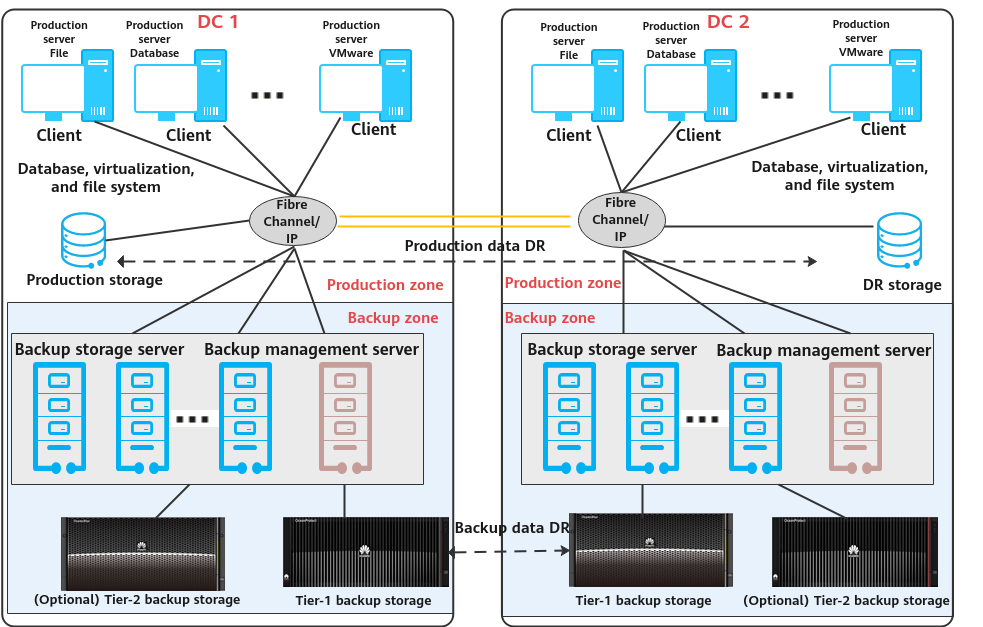
Solution Components
- Backup software: Mainstream backup software includes NetWorker, Veritas NetBackup, Veeam, and Commvault.
- Backup management server: manages components in the backup system. It is used to create, execute, and schedule backup jobs and configure backup policies. It can be deployed independently or together with the media server.
- Backup agent client: It is installed on protected application production servers and VMs, responds to backup job scheduling by the backup management server, collects and manages data to be protected, and transmits the data to the backup storage server.
- Backup storage server (also called media server): It is deployed independently and responds to job scheduling by the backup management server. It processes backup data flows and manages backup data transmission and storage devices. Some vendors provide backup data deduplication and compression on the backup storage server.
- Backup storage: It is connected to the backup storage server and used to receive and store backup data. Some backup storage devices provide deduplication and compression. Based on service requirements, there are tier-1 backup storage and tier-2 backup storage. Tier-1 backup storage provides rapid and efficient backup and restoration with optimal performance. As tier-1 backup storage is expensive, deduplication and compression are important. Tier-2 backup storage provides long-term retention (LTR) at a low cost. Backup copies before a certain point in time can be migrated to tier-2 backup storage for an optimal comprehensive retention cost. Common backup storage types include backup storage, general-purpose storage, virtual tape library (VTL), object storage, and tape library.
Solution Description
- During backup, the backup management server delivers a backup scheduling command to the backup agent. Then, the backup agent collects and transmits data based on the set backup policy. The backup storage server processes the data transmitted by the backup agent, writes the data to the backup storage in a certain format, and records indexes.
- Performance of a single backup storage server is limited. Backup storage server scale-out is supported for performance improvement.
- Backup data replication: Remote backup data disaster recovery (DR) is required to meet compliance and data security requirements. Data can be replicated and transmitted through the backup storage server or tier-1 backup device.
- Backup data LTR: LTR solutions apply to scenarios where backup copies need to be retained for a long time with rapid restoration available. Based on policies, latest copies are stored on tier-1 backup media with rapid backup, access, and restoration supported. Copies that need to be retained for a long time are stored on tier-2 backup media with lower costs. In this way, the overall retention cost is optimal.
This document describes the backup storage solution based on the OceanProtect Backup Storage integrating backup software NetWorker.
2. Solution Introduction
Based on Huawei OceanProtect backup storage integrating NetWorker, the backup storage solution provides application system backup, backup copy replication, LTR, and dumping of backup copies from peer vendors’ systems.
2.1 Solution Components
2.1.1 NetWorker Backup Software
NetWorker is used for traditional application scenarios. It backs up data through the Client Direct, SAN, or server-free architecture and tiers the data to mainstream backup devices (disks, DD devices, and physical tape libraries). It also supports DR based on IP and Fibre Channel links.
It is tightly coupled with DataDomain (DD) to implement the following functions:
- VMware snapshot-level backup
- Deduplication (source deduplication, back-end deduplication, and deduplicated replication)
- Backup/Archive to S3 storage and the cloud
- Data ransomware protection (isolation using Air Gap, locking, detection, and analysis)
|
Feature |
Description |
|---|---|
|
File system backup |
Supports AIX, HP-UX, Solaris, and x86 platforms (Linux and Windows). |
|
OS backup |
Supports only Windows Server 2012 or later. For other OSs, third-party BMR software must be integrated to enable this feature. |
|
Virtualization backup |
Supports only VMware (must work with DD to perform backup) and Hyper-V. |
|
Database and application backup |
Supports only mainstream traditional databases outside the Chinese mainland. New applications are not supported. |
|
Remote replication |
1. Uses the clone function of NetWorker and does not support deduplication (for disks and physical tape libraries). 2. Uses replication provided by DD and supports deduplication. |
|
Big data platform backup |
Must use pre- and post-processing scripts to back up data. Direct backup is not supported. |
|
Deduplication |
Not supported by NetWorker (no source deduplication, back-end deduplication, or deduplicated replication). Deduplication provided by DD is used. |
|
Snapshot-based backup |
|
|
Backup architecture |
Client Direct (direct backup), SAN, server-free, D2T, D2D, and D2D2C. |
|
Backup device types supported |
Physical/Virtual tape libraries, disk devices (NAS/Fibre Channel), and DD. Optical disc libraries are not supported. |
|
Direct backup to S3 storage and the cloud |
Direct backup is not supported. CloudBoost (for direct backup to S3 storage) has reached EOL. This function must be implemented using DD. |
|
License authorization |
Front-end capacity, no technical restrictions, sold together with PPDM and Avamar. |
2.1.2 OceanProtect Backup Storage
Product Positioning
As the amount, types, and growth rate of data change exponentially, enterprises face increasing data loss risks due to human errors, viruses, natural disasters, and network security threats. Therefore, data protection becomes increasingly important.
OceanProtect backup storage features rapid backup, rapid restoration, efficient reduction, and solid resilience. It implements efficient backup and restoration with the TCO greatly reduced. It is widely used in government, finance, carrier, healthcare, and manufacturing industries. In addition, it offers easy management and convenient local/remote maintenance, significantly reducing device management and maintenance costs.
OceanProtect backup storage is available in SSD and HDD forms.
- SSD form: The system supports only SSDs. Service data and metadata are stored on SSDs.
- HDD form: The system supports SSDs and HDDs. Service data is stored on a storage pool composed of HDDs. SSDs only store system metadata. SSDs delivering higher performance accelerate metadata access, improving read and write performance.
Product Highlights
With the active-active high-reliability architecture and full-process acceleration, OceanProtect backup storage features rapid backup, rapid restoration, efficient reduction, and solid resilience.
- Rapid backup and restoration
- Full-process acceleration is implemented. The front-end network protocol offload technology reduces the CPU pressure, and back-end CPU multi-core parallel scheduling is implemented. Dedicated cores are used through grouping and task partitioning, efficiently improving the processing capability of nodes.
- Based on backup service characteristics, multiple sequential data flows are aggregated for read and write, greatly improving bandwidth performance. Source deduplication reduces the amount of data to be transmitted over the network, shortening the backup duration.
- The system provides high IOPS performance and can work with mainstream backup software. Backup image data can be accessed instantly, enabling fast utilization of backup data.
- Efficient reduction
- Accurate backup data segmentation, backup data aggregation preprocessing, and multi-layer inline variable-length deduplication are used to increase the logical capacity and reduce the TCO.
- Data flow features can be identified. Combination-based compression, high-performance predictive encoding, and byte-level compaction are used to improve the data reduction ratio.
- Source deduplication and deduplicated replication are used to reduce network bandwidth costs.
- Solid resilience
- The active-active redundant hardware architecture design ensures that ongoing backup jobs, if a controller is faulty, can be switched over in seconds without being interrupted.
- Protocol encryption, replication link encryption, array encryption, secure snapshot, and WORM functions are used to ensure security and availability of copies.
2.2 Solution Architecture
2.2.1 Overall Solution Architecture
Figure 2-1 Overall architecture of the OceanProtect Backup Storage+NetWorker solution
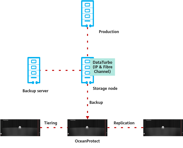
Solution overview:
- Backup and restoration
NetWorker is mainly used for backup in traditional application scenarios. It can be integrated in Advance File Type Device (AFTD) mode (through NAS) to implement backup, restoration, replication, and tiering.
Backup: NetWorker does not provide deduplication. After DD is replaced with the OceanProtect, client data is backed up to the OceanProtect for deduplication and compression. Alternatively, DataTurbo can be used to implement source deduplication.
After OceanProtect is used, NetWorker cannot perform snapshot-based backup for a VMware VM as a whole. Instead, it can only back up VM files or applications to OceanProtect in guest mode, which is inefficient and is not recommended.
- Remote replication
NetWorker does not provide functions similar to A.I.R. of NetBackup. After DD is replaced with the OceanProtect, one of the following replication solutions can be used based on the remote architecture of backup servers:
- Use the NetWorker filtering policy to clone backup sets to the remote site. Backup data is replicated to the remote site by storage nodes. This method does not support deduplicated replication.
- Replicate the underlying data of OceanProtect X8000 to the remote site, and deduplicated replication can be enabled. Use DR commands to restore index information.
- Tiering for LTR
The backup software does not support data tiering to the cloud. When it works with DD, archive data is stored on S3 storage for LTR. To implement data tiering to the cloud, NetWorker must use the Cloud Tier function of DD. If it works alone, it can only back up data to tape libraries.
The NetWorker+OceanProtect solution uses the tiering capability of the OceanProtect to tier data to OceanStor Pacific objects.
2.2.2 Backup Solution Architecture
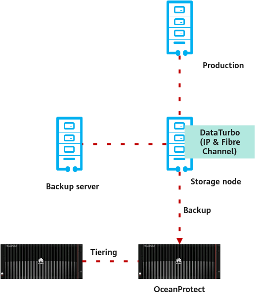
Figure 2-2 Backup solution architecture
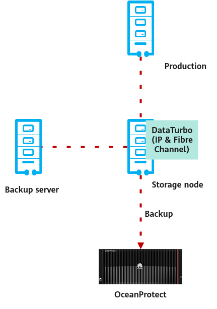
Backup solution architecture overview:
- NetWorker components:
- NetWorker Server: executes different services such as backup and restoration session control and monitoring. It can also be used as a local storage node or to control multiple remote storage nodes.
- NetWorker Management Console (NMC) Server: manages the NetWorker Server and NetWorker clients and provides them with report and monitoring capabilities. NMC authenticates users based on the NetWorker authentication service.
- NetWorker Client: is a physical machine or VM on which the NetWorker backup client can be installed.
- NetWorker Storage Node: is a host computer connected to storage devices (including the NetWorker server). Backup data can be stored on local or remote storage nodes. Storage nodes can control tapes and disks.
- Datazone: Generally, a datazone includes NetWorker Server, related clients, and storage nodes. Datazones can be added to meet increasing backup requirements.
- Integration description
NetWorker provides backup software functions. The OceanProtect Backup Storage (as storage media) connects to NetWorker. NetWorker writes client backup data to the OceanProtect Backup Storage.
- Integration mode
NetWorker can be integrated with and back up data to disk storage devices in the following modes:
- File Type Device (FTD): is a basic integration mode existing for many years. Generally, only legacy systems use this mode.
- Advanced File Type Devices (AFTD): supports concurrent backup and restoration. Generally, AFTD can be configured through local disk, NAS, and CIFS modes.
- DD Boost: is a direct and efficient mode for integration with Data Domain. Source deduplication and compression are supported.
- Deduplication and compression
NetWorker does not provide deduplication. After DD is replaced with the OceanProtect, client data is backed up to the OceanProtect for deduplication and compression. Alternatively, DataTurbo can be used to implement source deduplication. The deduplication ratio can reach up to 72:1.
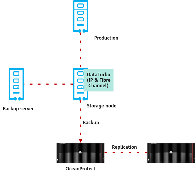
2.2.3 Backup Copy Replication Solution Architecture
There are two backup copy replication solutions.
- Use the NetWorker filtering policy to clone backup sets to the remote site. Backup data is replicated to the remote site by storage nodes. This method does not support deduplicated replication.
- Replicate the underlying data of OceanProtect X8000 to the remote site, and deduplicated replication can be enabled. Use DR commands to restore index information.
Solution 2 is preferred because it delivers replication provided by backup storage to ensure a shorter I/O path and reduce read/write performance overheads of backup software replication.
The following figure shows typical replication provided by NetWorker and the OceanProtect Backup Storage.
Figure 2-3 Replication provided by NetWorker and the OceanProtect Backup Storage
2.2.4 Tiering Solution Architecture
Figure 2-4 Tiering solution architecture
Tiering solution architecture overview:
The backup software does not support data tiering to the cloud. When it works with DD, archive data is stored on S3 storage for LTR. To implement data tiering to the cloud, NetWorker must use the Cloud Tier function of DD. If it works alone, it can only back up data to tape libraries.
The NetWorker + OceanProtect solution uses the tiering capability of OceanProtect to tier data to OceanStor Pacific objects.
Constraints:
- Deduplication is not supported for data tiering.
- Tiering cannot be used together with replication provided by the OceanProtect.
- Tiering and ransomware protection cannot be used together.
2.3 Constraints
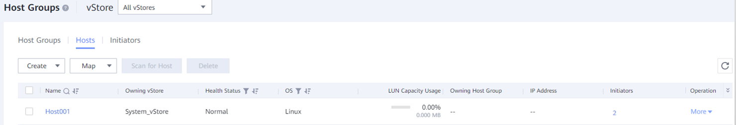
- If the backup software integrates with the OceanProtect Backup Storage through the DataTurbo protocol, a DataTurbo administrator can be created only under the default vStore System_vStore. For this reason, this solution does not apply to multi-vStore scenarios.
- For 1.7.0 and earlier versions, DataTurbo administrators can be created only under the System_vStore vStore. For V200R001C10 and later versions, DataTurbo administrators can be created under all vStores. If you need to create a DataTurbo user under a vStore other than System_vStore, create the vStore first.
- A maximum of 16 DataTurbo users can be created.
- Constraints on SmartMobility:
- A file system that uses SmartMobility does not support file system clone.
- A file system that uses SmartMobility does not support file clone.
- A file system that uses SmartMobility does not support WORM.
- A file system that uses SmartMobility does not support migration of non-hosted files of ADS.
- A file system that uses SmartMobility does not support migration of the xattr attribute.
3. Planning Suggestions
3.1 Network Planning for Different OceanProtect Models
3.2 Backup Planning for Connected Applications
3.3 Planing for System Backup Capacity and Performance
3.1 Network Planning for Different OceanProtect Models
A customer can select OceanProtect X3000, X6000, X8000, and X9000 based on different backup capacity and performance requirements. The networking configuration principles of all models must comply with the principles described in 4.3 Configuration Planning for Connection to NetWorker.
3.2 Backup Planning for Connected Applications
3.2.1 Connecting to the Backup Software
In the NetWorker backup software system, the application host to be backed up is registered as a client and added to a group for management. The group is associated with a policy, in which a work flow is configured to control backup and other behavior. After the work flow is started, the backup software process on the client host reads, sorts, and sends the data to be backed up to the configured target media pool for backup.
A media pool consists of devices. The devices are configured to point to the mount paths or network locations in the storage nodes to write backup copy data to the file system in the OceanProtect Backup Storage.
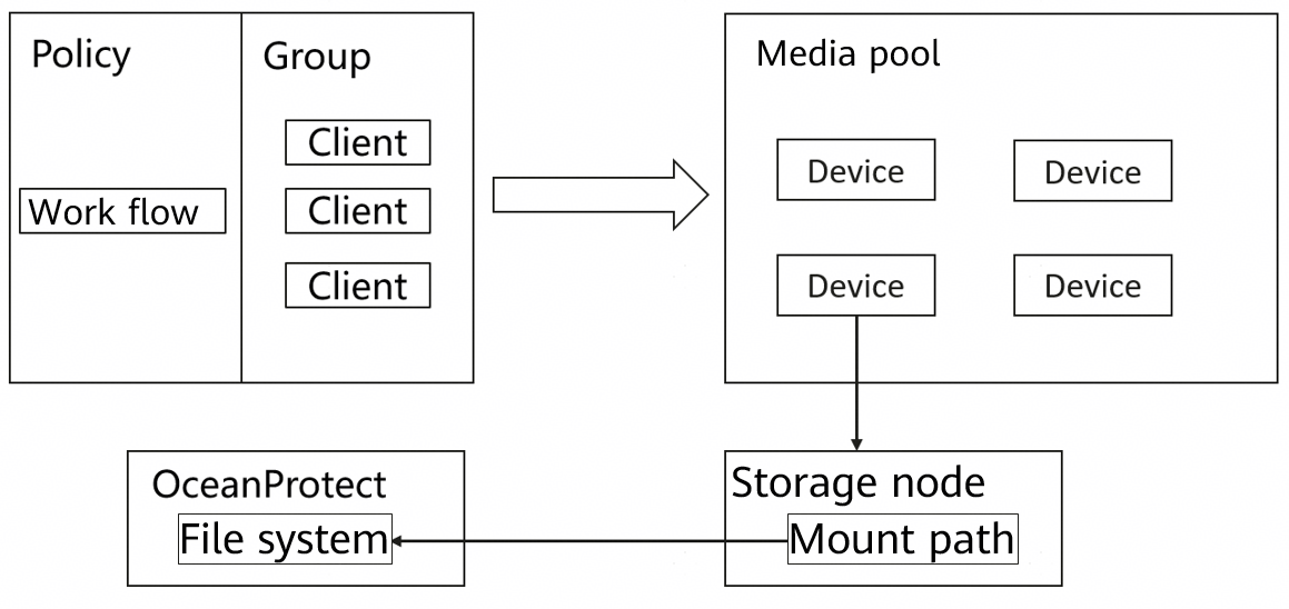
The following figure shows the simplified physical networking of this solution. Backup data is transferred from the production servers (clients) to the OceanProtect Backup Storage through the storage node servers.
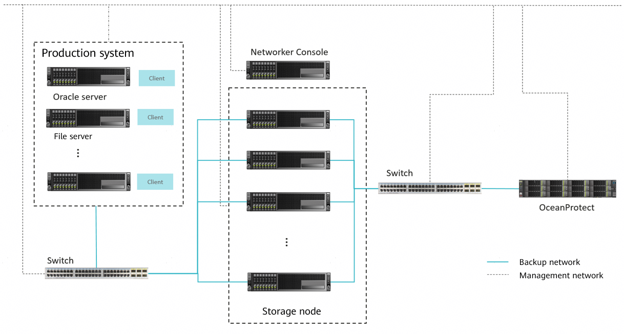
3.2.2 Planning Suggestions for Connecting Oracle Databases and Host Files for Backup
The NetWorker+OceanProtect Backup Storage solution supports connection to various production application systems within the compatibility and restrictions of the NetWorker backup software for backup. The overall networking design complies with the maximum performance range of the OceanProtect Backup Storage. It must be ensured that the end-to-end network does not have performance bottlenecks based on the compute resources and performance of the production servers (clients) and backup media servers (storage nodes).
The following describes how to back up the Oracle database.
Oracle database backup networking

Oracle
- In this example, backup is performed for four Oracle hosts that connect to the production storage OceanStor Dorado 6000 V6.
- Front-end network: The four Oracle hosts that connect to the production storage separately connect to a switch through 3 × 10GE links for communication with the production storage.
- Back-end network: Each server uses 3 × 10GE links to connect to a 10GE switch for communication with the storage nodes. The servers are configured with bonding (mode 0) and the switches are configured with Eth-Trunk.
Production Storage
- In this example, one OceanStor Dorado 6000 V6 storage device is used. LUNs are created and mapped to the Oracle hosts as storage volumes for Oracle data files and log files.
- Network: The production storage uses 12 × 10GE iSCSI links to connect to a switch for communication with the four Oracle hosts.
NetWorker Console & Storage Nodes
- In this example, one physical server is deployed as the NetWorker Console. The server can participate in backup service traffic transmission or only control services.
- Two storage node hosts are deployed to receive data sent by the client hosts and write backup copy data to the storage.
- Front-end network: The 4 × 10GE network (bond0) is used to connect to a 10GE switch for communication with the Oracle hosts (NetWorker clients).
- Back-end TCP network: The 2 × 10GE network (not bonded) is used to connect to a 10GE switch for communication with OceanProtect X8000.
- Back-end Fibre Channel network: The 2 × 16 Gbit/s Fibre Channel links are used to connect to a Fibre Channel switch for communication with OceanProtect X8000.
Select either of the back-end networks based on the site requirements.
OceanProtect X8000
Select either of the networks based on the site requirements.
TCP network: OceanProtect X8000 uses 4 × 10GE links to connect to a 10GE switch for communication with the storage node hosts.
Fibre Channel network: OceanProtect X8000 uses 4 × 16 Gbit/s Fibre Channel links to connect to a Fibre Channel switch for communication with the storage node hosts.
3.3 Planing for System Backup Capacity and Performance
3.3.1 Overall Capacity and Performance Planning
Before backup solution planning and design, survey the production system and plan the backup system. The procedure is as follows:
- Configure a backup policy.
Survey the service systems to be backed up, and make a proper backup policy for each service system based on service requirements, for example, full backup every week, incremental backup every day, and backup copy retention for one month.
Table 3-1 shows typical backup policies.
Table 3-1 Typical backup policies
|
No. |
Backup Object |
Incremental Backup Frequency |
Incremental Backup Copy Retention Period (Days) |
Number of Incremental Backup Copies |
Full Backup Frequency |
Full Backup Copy Retention Period (Days) |
Number of Full Backup Copies |
|---|---|---|---|---|---|---|---|
|
1 |
OS |
Every day |
90 |
87 |
Every month |
90 |
4 |
|
2 |
File |
Every day |
90 |
77 |
Every week |
90 |
14 |
|
3 |
|
Every day |
365 |
353 |
Every month |
365 |
13 |
|
4 |
Database |
Every day |
90 |
77 |
Every week |
90 |
14 |
- Calculate backup capacity.
Survey production capacity of each service system to be backed up and the data change rate (such as daily, weekly, monthly, and annual change rates). Based on the preceding information, use eDesigner to calculate the deduplication ratio and capacity after deduplication.
Table 3-2 shows typical backup capacity calculation.
Table 3-2 Backup capacity calculation
|
No. |
Site |
Backup Object |
Initial Capacity (GB) |
Capacity Growth Rate |
Three-Year Capacity (GB) Before Deduplication |
Data Deduplication Ratio |
Three-Year Capacity (GB) After Deduplication |
|---|---|---|---|---|---|---|---|
|
1 |
Data center |
OS |
5,000 |
1% per month |
32,177 |
5:1 |
6,435 |
|
2 |
File |
2,500 |
2% per month |
81,206 |
5:1 |
16,241 | |
|
3 |
|
1,000 |
2% per month |
33,199 |
8:1 |
4,150 | |
|
4 |
Database |
5,000 |
1% per month |
112,042 |
3:1 |
37,347 | |
|
5 |
Total: |
13,500 |
258,624 |
64,175 | |||
|
6 |
Remote site 1 |
OS |
2,500 |
1% per month |
16,089 |
5:1 |
3,218 |
|
7 |
File |
1,250 |
2% per month |
40,603 |
5:1 |
8,121 | |
|
8 |
Total: |
3,750 |
56,692 |
11,339 | |||
|
9 |
Remote site 2 |
OS |
5,000 |
1% per month |
32,177 |
5:1 |
6,435 |
|
10 |
File |
3,000 |
2% per month |
97,447 |
5:1 |
19,489 | |
|
11 |
Total: |
8,000 |
129,624 |
25,924 | |||
|
12 |
Total (all sites): |
25,250 |
444,940 |
101,438 | |||
- Calculate backup performance and bandwidth.
It is recommended that initial full backup be performed after a backup system is delivered. Plan the backup time window for the initial full backup. In addition, plan the daily backup time window for periodic backup or incremental backup based on the required backup policy. Generally, it is recommended that periodic full backup of each application system be performed in staggered mode. Complete full backup and incremental backup jobs of each application system within a period based on backup policies.
Table 3-3 shows typical backup performance and bandwidth calculation.
Table 3-3 Backup performance and bandwidth calculation
|
No. |
Site |
Backup Object |
Daily Full Backup Volume (GB) After Three Years |
Backup Time Window (Hours) |
Backup Bandwidth (MB/s) |
|---|---|---|---|---|---|
|
1 |
Data center |
OS |
7,154 |
4 |
509 |
|
2 |
File |
5,100 |
2 |
725 | |
|
3 |
|
2,040 |
1 |
580 | |
|
4 |
Database |
7,154 |
5 |
407 | |
|
5 |
Remote site 1 |
OS |
3,577 |
2 |
509 |
|
6 |
File |
2,550 |
2 |
363 | |
|
7 |
Remote site 2 |
OS |
7,154 |
4 |
509 |
|
8 |
File |
6,120 |
3 |
580 |
- Create a replication policy.
If backup copy replication is required for DR, a replication policy must be created. You need to plan the execution window for replication jobs.
Table 3-4 shows typical replication policies.
Table 3-4 Replication policies
|
No. |
Source Site |
Target Site |
Replication Mode |
Replication Time Window |
|---|---|---|---|---|
|
1 |
Remote site 1 |
Data center |
Replicate the underlying data of OceanProtect X8000 to the remote site. |
7:00 to 11:00 |
|
2 |
Remote site 2 |
Data center |
Replicate the underlying data of OceanProtect X8000 to the remote site. |
7:00 to 11:00 |
|
3 |
Data center |
Remote site 2 |
Replicate the underlying data of OceanProtect X8000 to the remote site. |
11:00 to 21:00 |
- Calculate replication performance and bandwidth.
Determine the replication time window based on service requirements. Calculate replication performance based on the volume of data to be replicated.
Maximum volume of data to be replicated per day per site = ∑(Full backup data volume of all applications/Deduplication ratio)
Table 3-5 shows a typical example of calculating replication bandwidth.
Table 3-5 Typical example of calculating replication bandwidth
|
No. |
Source Site |
Target Site |
Volume (GB) of Data to Be Replicated Every Day |
Replication Time Window (Hours) |
Replication Bandwidth (MB/s) |
|---|---|---|---|---|---|
|
1 |
Remote site 1 |
Data center |
1,225 |
2 |
174 |
|
2 |
Remote site 2 |
Data center |
2,655 |
4 |
189 |
|
3 |
Data center |
Remote site 2 |
5,090 |
9 |
161 |
3.3.2 OceanProtect Backup Storage Configuration Planning
Backup Capacity and Performance Planning
- Backup capacity calculation
Generally, capacity of OceanProtect X8000 is planned based on the backup data capacity and retention period.

For commercial configurations of OceanProtect X8000, visit https://app.huawei.com/unistar/edesigner/#/.
- Backup performance calculation
Generally, backup performance of a backup system is planned based on the backup time window and backup capacity.
Storage Resource Planning
- Disk type planning: Storage pools can be created using SSDs and HDDs. Table 3-6 describes disk type planning.
Table 3-6 Disk type planning
|
Storage Form |
OceanProtect X8000 (All-Flash) |
OceanProtect X8000 (HDD) |
|
Disk Type |
A storage pool contains only SSDs. |
A storage pool contains SSDs and HDDs. |
|
Disk Quantity |
|
|
- Storage capacity planning: Generally, capacity of OceanProtect X8000 is planned based on the backup data capacity and retention period.
- Compression mode planning: Storage pools support high reduction ratio (default) and high performance modes.
The high reduction ratio mode delivers higher reduction ratio than the high performance mode.
- Storage pool planning: A storage pool is a container that stores resources. It provides storage space for all application servers. For core services, RAID-TP is recommended. Table 3-7 describes storage pool protection levels.
Table 3-7 Storage pool protection levels
|
Protection Level |
Number of Parity Bits |
Redundancy and Data Restoration |
Maximum Number of Disks Allowed to Fail Simultaneously |
|---|---|---|---|
|
RAID 6 (default) |
2 |
High. Parity data is distributed in different chunks (CKs). In each chunk group (CKG), parity data occupies the space of two CKs. The failure of any two CKs can be tolerated. If three or more CKs fail simultaneously, RAID 6 protection cannot be provided. |
2 |
|
RAID-TP |
3 |
High. Parity data is distributed in different CKs. In each CKG, parity data occupies the space of three CKs. The failure of any three CKs can be tolerated. If four or more CKs fail simultaneously, RAID-TP protection cannot be provided. |
3 |
File System Planning
- File system planning: Table 3-8 describes key parameters in file system planning.
Table 3-8 File system planning
|
Parameter |
Description |
|---|---|
|
Capacity |
File system capacity is planned based on service requirements. |
|
Quantity |
To ensure performance, it is recommended that four file systems be configured. |
|
Application type |
|
- File system sharing: OceanProtect X8000 provides CIFS, NFS, and DataTurbo shares. If source deduplication is used, select the DataTurbo share. For details about OS and backup software versions supported by the DataTurbo client, visit the following website:
https://info.support.huawei.com/storage/comp/#/oceanprotect
Network Planning
- Physical port planning
- Quantity planning: Plan the numbers of required NICs and ports based on backup network bandwidth requirements.
- Configuration planning: An OceanProtect X8000 device has two controllers. To ensure reliability, NICs must be evenly distributed to controllers A and B.
- Logical port planning
- Quantity planning: Logical ports are created for running NAS services. It is recommended that at least one logical port be configured for each physical port.
- Configuration planning: An OceanProtect X8000 device has two controllers (A and B). For file system mounting, it is recommended that file systems of controllers A and B use logical ports of corresponding controllers, respectively.

To achieve a good deduplication effect, you are advised to disable the deduplication and compression functions of backup software and disable the compression and encryption functions of applications to be backed up. For example, disable compression and encryption of Oracle RMAN.
4. Configuration Example
In this chapter, OceanProtect X8000 integrates NetWorker through the DataTurbo protocol to back up the Oracle application. Backup, restoration, and remote replication configuration processes as well as test results are provided.
4.2 Hardware and Software Configuration
4.3 Configuration Planning for Connection to NetWorker
4.4 NetWorker Backup and Restoration Configuration
4.5 Configuring the Remote Replication Environment
4.6 Best Practice Verification Examples
4.1 Solution Networking
TCP Network
Figure 4-1 shows an example of the TCP networking diagram in this best practice.
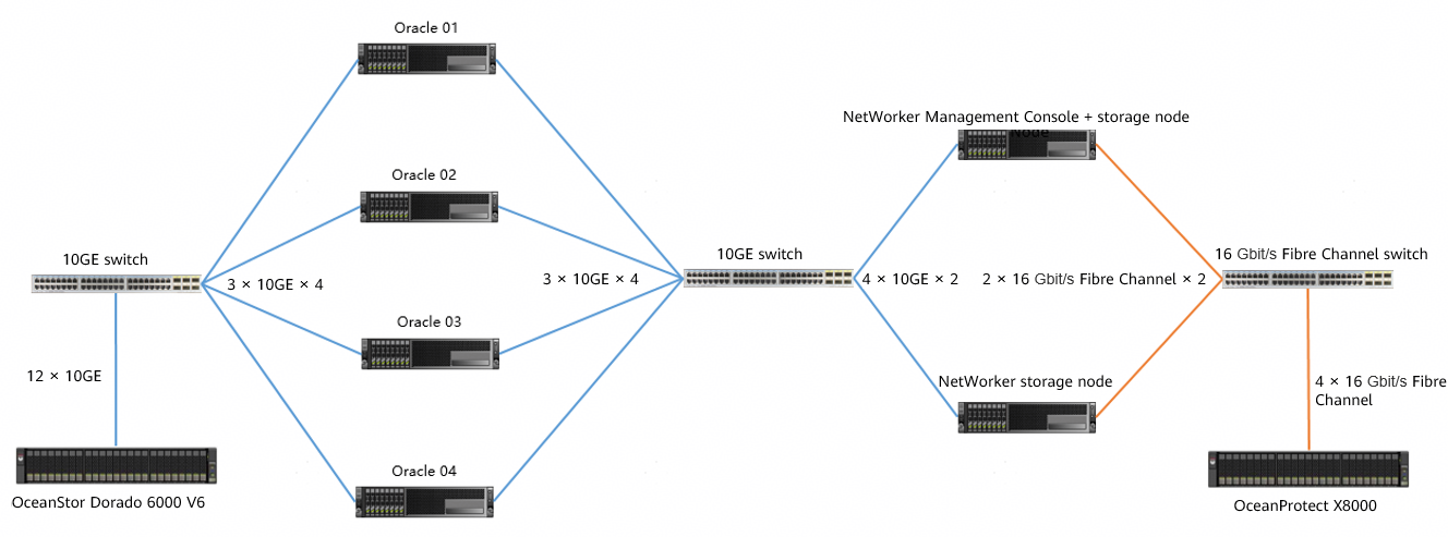
Figure 4-1 TCP networking diagram for Oracle backup using OceanProtect X8000 and NetWorker
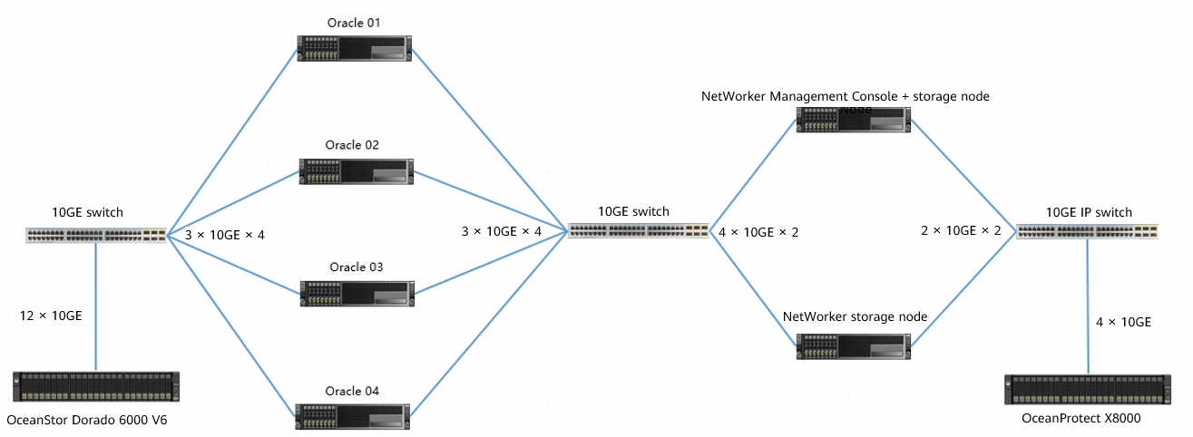

Figure 4-1 is for reference only. For details about connections between OceanProtect X8000 controller enclosures and application servers, between controller enclosures and disk enclosures, and between controller enclosures, see « Installation Planning and Preparation > Installation Planning > Cabinet Layout and Connection Planning » in the OceanProtect X6000, X8000 Backup Storage 1.x and V200R001 Hardware Installation Guide. TCP and Fibre Channel network connections are distinguished in « Connection Planning Between the Controller Enclosure and the Application Server > Connection Plans for File Services ».
The networking is described as follows:
- Oracle: Four physical Oracle hosts are deployed with one production storage device connected.
- Four Oracle hosts connect to OceanStor Dorado 6000 V6 through the 10GE switch. Each Oracle host uses 3 × 10GE iSCSI links, and OceanStor Dorado 6000 V6 uses 12 × 10GE links (6 × 10GE links for controller A and controller B separately).
- LUNs are created on OceanStor Dorado 6000 V6 and mounted to the Oracle hosts through the iSCSI protocol. These LUNs are used as storage volumes for Oracle data files and archive logs.
- Each Oracle host uses 3 × 10GE optical fibers to connect to the NetWorker storage nodes through a 10GE switch. Port bonding in mode 0 is configured.
- NetWorker Management Console (NMC): It is co-deployed with a NetWorker storage node on a physical server.
- NetWorker storage node: Two storage nodes are deployed and connected to the Oracle hosts through a 10GE switch and connected to OceanProtect X8000 through a Fibre Channel switch.
- The two storage nodes use 4 × 10GE ports for port binding (in mode 0) and are connected to the Oracle hosts through a 10GE switch where the Eth-Trunk is configured.
- Each storage node uses 2 × 10GE optical fibers to connect to OceanProtect X8000 through an IP switch.
- OceanProtect X8000: connects to an IP switch through 4 × 10GE optical fibers. Each controller uses 2 × 10GE optical fibers. Four physical ports connect to the backup servers for backup links.
Fibre Channel Network
Figure 4-2 shows an example of the Fibre Channel networking diagram in this best practice.
Figure 4-2 Fibre Channel networking diagram for Oracle backup using OceanProtect X8000 and NetWorker
The networking is described as follows:
- Oracle: Four physical Oracle hosts are deployed with one production storage device connected.
- The four Oracle hosts are connected to OceanStor Dorado 6000 V6 through a 10GE switch. Each Oracle host uses 3 × 10GE iSCSI links. OceanStor Dorado 6000 V6 uses 12 × 10GE links (6 × 10GE for controller A and controller B separately).
- LUNs are created on OceanStor Dorado 6000 V6 and mounted to the Oracle hosts through the iSCSI protocol. These LUNs are used as storage volumes for Oracle data files and archive logs.
- Each Oracle host uses 3 × 10GE optical fibers to connect to the NetWorker storage nodes through a 10GE switch. Port bonding in mode 0 is configured.
- NMC: It is co-deployed with a NetWorker storage node on a physical server.
- NetWorker storage node: Two storage nodes are deployed and connected to the Oracle hosts through a 10GE switch and connected to OceanProtect X8000 through a Fibre Channel switch.
- The two storage nodes use 4 × 10GE ports for port binding (in mode 0) and are connected to the Oracle hosts through a 10GE switch where the Eth-Trunk is configured.
- Each storage node uses 2 × 16 Gbit/s Fibre Channel ports to connect to OceanProtect X8000 through a Fibre Channel switch.
- OceanProtect X8000: connects to a Fibre Channel switch through 4 × 16 Gbit/s optical fibers. Each controller uses 2 × 16 Gbit/s Fibre Channel optical fibers. Four physical ports connect to the backup servers for backup links.
4.2 Hardware and Software Configuration
4.2.1 Hardware Configuration
|
Name |
Description |
Quantity |
Function |
|---|---|---|---|
|
Oracle server |
x86 server CPU: 2 x Intel(R) Xeon(R) Gold 6130 Memory: 256 GB Network: 6 x 10GE optical ports |
2 |
Oracle host where the Oracle 11g database is installed. |
|
Oracle server |
x86 server CPU: 2 x Montage Jintide(R) C6230R Memory: 256 GB Network: 6 x 10GE optical ports |
2 |
Oracle host where the Oracle 11g database is installed. |
|
NetWorker Management Console |
x86 server CPU: 2 x Intel(R) Xeon(R) Silver 4214R Memory: 128 GB Network: 4 x 10GE optical ports + 2 x 16 Gbit/s Fibre Channel |
1 |
Manages NetWorker Storage Nodes and NetWorker Client. It is deployed together with one NetWorker Storage Node. |
|
NetWorker Storage Node |
x86 server CPU: 2 x Intel(R) Xeon(R) Silver 4214R Memory: 128 GB Network: 4 x 10GE optical ports + 2 x 16 Gbit/s Fibre Channel |
2 |
NetWorker proxy server, which reads and writes backup data and manages NetWorker storage media. |
|
Production storage |
Huawei OceanStor Dorado 6000 with two controllers, 25 x 7.68 TB SSDs, and 4 x 4-port 10 Gbit/s SmartIO interface modules |
1 |
Production storage that stores production service data to be backed up and tested. |
|
Backup service switch |
Huawei CE6850 |
2 |
10GE switch on the backup service plane. |
|
Fibre Channel service switch |
Huawei SNS2248 |
1 |
16 Gbit/s Fibre Channel switch that connects NetWorker Storage Node hosts to OceanProtect X8000. |
|
TCP service switch |
Huawei CE6850 |
1 |
10GE IP switch that connects NetWorker Storage Node hosts to OceanProtect X8000. |
4.2.2 OceanProtect X8000 (All-Flash) Configuration
Table 4-1 OceanProtect X8000 (all-flash) configuration
|
Name |
Description |
Quantity |
|---|---|---|
|
OceanProtect controller enclosure |
Huawei OceanProtect X8000 with two controllers |
2 |
|
10GE front-end interface module |
4 x 10 Gbit/s SmartIO interface modules |
2 |
|
SAS SSD |
Huawei 7.68 TB SAS SSDs |
25 |
4.2.3 Test Software and Tools
Table 4-2 Software description
|
Software Name |
Description |
|---|---|
|
OceanStor DataTurbo 1.6.0 |
Source deduplication client software. It is deployed on the backup server for source deduplication and compression on backup data to reduce the amount of physical data transmitted from the backup server to storage and improve the overall bandwidth of backup services. |
|
NetWorker 18.2.0.1 |
NetWorker 18.2.0.1 backup software |
|
Oracle 11g |
Oracle database |
|
CentOS 7.6 |
CentOS Linux open-source OS |
|
Swingbench 2.6 |
Third-party tool for generating Oracle test data |
|
SSH client software |
SSH terminal connection tool |
4.3 Configuration Planning for Connection to NetWorker
- Storage pool on OceanProtect X8000: Create a storage pool with 25 x 7.68 TB SAS SSDs, and set the RAID policy to RAID 6.
- OceanProtect X8000 file system: Take two backup media servers as an example. Plan two file systems (one for each controller) and 100 TB logical capacity for each file system.
- Logical ports of OceanProtect X8000: OcanProtect X8000 is connected to the two front-end backup media servers through 4 x 10GE physical links. Each physical port is configured with one logical port.
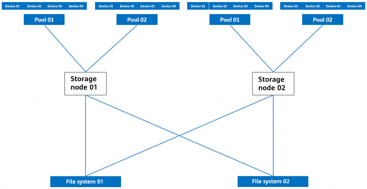
- Storage pool planning:
- On OceanProtect X8000, create two file systems that are owned by controllers A and B, respectively.
- Mount the two file systems to each backup media server.
- Four devices are created for each mount point on each backup media server. There are eight devices in total. The four devices that belong to the same file system form a pool. Therefore, each backup media server has two pools. In addition, if the same data is backed up for multiple times, ensure that it is backed up to the same pool each time. In this way, data can be deduplicated and compressed.
Figure 4-3 shows the mounting details.
Figure 4-3 Mounting file systems

Backup principle: Periodic backup copy data of the same type of applications is written to the same deduplication domain.
Networking principles:
- It is recommended that one pool be planned for a type of applications. The mapping relationship between pools and file systems is one-to-one and that between pools and backup media servers is two-to-one.
- To maximize the performance of OceanProtect X9000 HDDs, you must configure 16 file systems.
The backup performance of the backup software is related to the number of mount points. Increasing the number of mount points helps improve the backup performance. Therefore, two file systems are planned for each NetWorker backup media server.
4.4 NetWorker Backup and Restoration Configuration
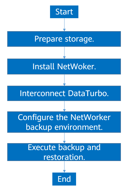
4.4.1 Configuration Process
Figure 4-4 Solution configuration process
4.4.2 Preparing Storage
According to planning in this solution, create two file systems and DataTurbo shares on OceanProtect X8000. The configuration procedure is as follows: Create a storage pool, create logical ports, create a file system, and create a share.
4.4.2.1 Creating a Storage Pool on OceanProtect X8000
Step 1 Create a storage pool on OceanProtect X8000. Select 25 disks to create a storage pool. Set RAID Policy to RAID 6, select the controller enclosure, and set Required Disks to the value of Available Disks.
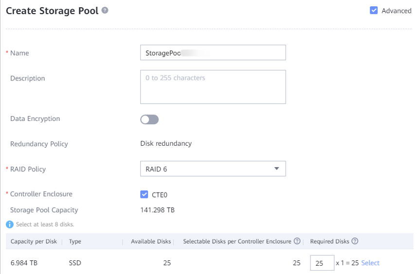
Step 2 Click Advanced and set Compression Mode to High reduction ratio (default value) or High performance. In this best practice, set it to High reduction ratio.
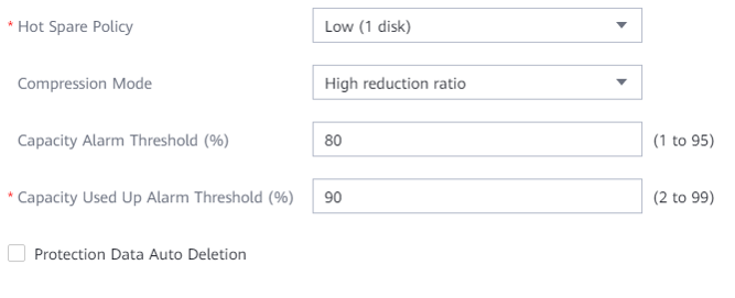
—-End
4.4.2.2 Creating a vStore DataTurbo Administrator
Step 1 Choose Services > vStore Service > vStores. On the displayed page, click System_vStore. Switch to the User Management tab page, and click Create. On the displayed page, set Role to vStore DataTurbo administrator, specify Username, Password, and Confirm Password, and click OK.
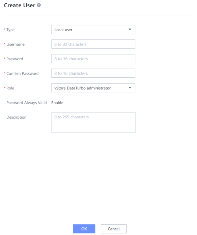
—-End
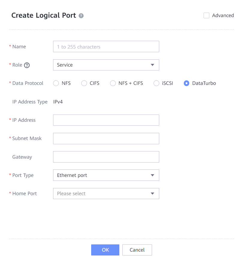
4.4.2.3 Creating Logical Ports on OceanProtect X8000 (DataTurbo over TCP)
If a DataTurbo over TCP network is used, you need to configure logical ports. If this network is not used, see 4.4.2.4 Creating Channel LUNs on OceanProtect X8000 (DataTurbo over Fibre Channel). In this practice, OceanProtect X8000 has four physical ports, with each physical port configured with a logical port. Therefore, create a total of four logical ports and set Data Protocol to DataTurbo.
The following figure shows a logical port configuration example.
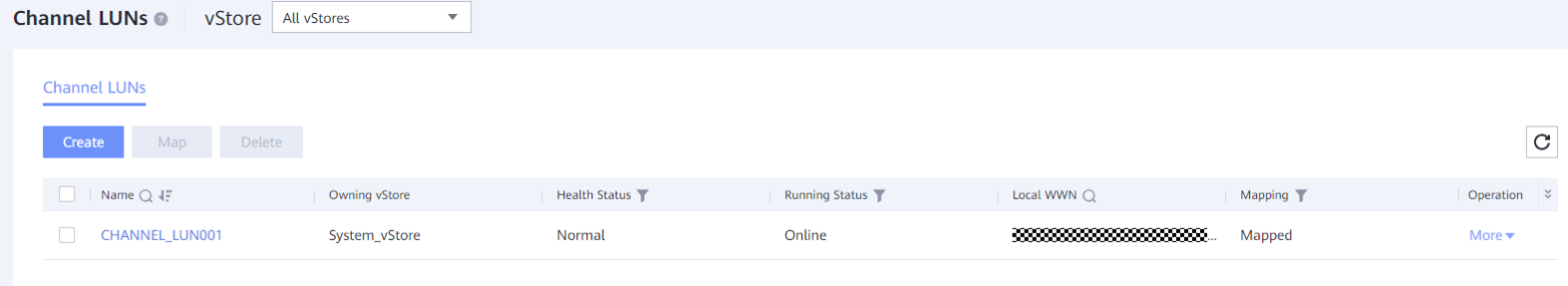
4.4.2.4 Creating Channel LUNs on OceanProtect X8000 (DataTurbo over Fibre Channel)
If a DataTurbo over Fibre Channel network is used, you need to configure channel LUNs. If this network is not used, see 4.4.2.3 Creating Logical Ports on OceanProtect X8000 (DataTurbo over TCP). Create channel LUN mappings on the OceanProtect Backup Storage and ensure that the backup server is connected to the storage over a Fibre Channel physical network.
For details about how to create channel LUN mappings, see « Configuring Basic Storage Services > Sharing File Systems > Configuring a DataTurbo Share > Configuring the Network > Method 2: Configuring the FC Network > Creating a Channel LUN » in the OceanProtect Backup Storage 1.6.0-1.7.0 and V200R001 Basic Storage Service Configuration Guide for File.
4.4.2.5 Creating File Systems and Shares
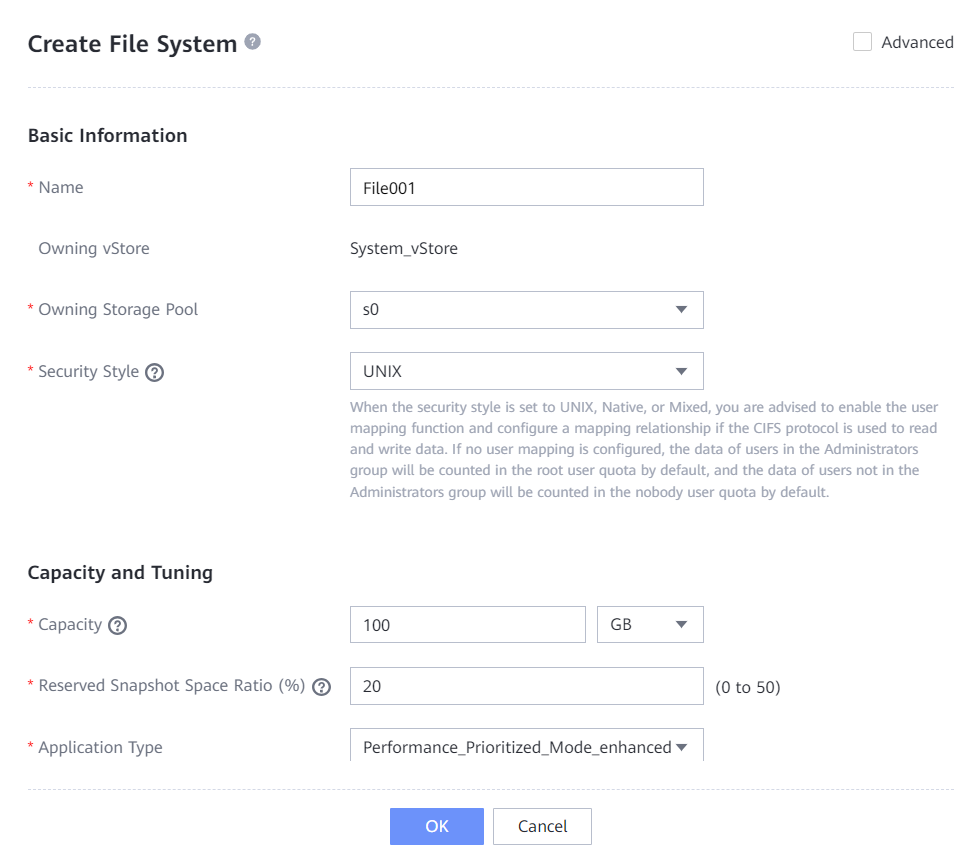
Step 1 Create two file systems (100 TB each). In this step, select the created storage pool.
Set Application type to Reduction_Prioritized_Mode_enhanced to save storage resources if Compression Mode is set to High reduction ratio, and to Performance_Prioritized_Mode_enhanced if Compression Mode is set to High performance for the storage pool.
The following figure shows a file system configuration example.
Step 2 Choose Services > Shares > DataTurbo Shares, and click Create. Select the file system for which you want to create a share, click Add, and select the vStore DataTurbo administrator created in 4.4.2.2 Creating a vStore DataTurbo Administrator.
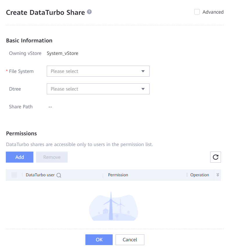
—-End
4.4.3 Installing NetWorker
In this backup solution, NetWorker 18.2 is used. NetWorker software must be installed on the NetWorker Server and storage nodes. For details about the NetWorker software installation process, see its official documentation. The configuration operations of NetWorker software of similar versions are similar.
4.4.4 Connection Through DataTurbo
This solution uses the SourceDedupe feature, which requires the DataTurbo protocol for connection with storage nodes. A DataTurbo share is created on OceanProtect X8000. To mount the corresponding file system to the backup host using the DataTurbo protocol, you must install OceanStor DataTurbo software and configure related parameters on the storage nodes.
4.4.4.1 Installation and Deployment
OceanStor DataTurbo must be installed on all backup hosts. For details, see « Installing, Upgrading, and Uninstalling the DataTurbo Client » in the OceanProtect Backup Storage 1.6.0-1.7.0 and V200R001 SourceDedupe User Guide. During the installation, select the high level.
4.4.4.2 Parameter Configuration
DataTurbo configuration is based on the network. If a TCP network is used, establish TCP links. If a Fibre Channel network is used, establish Fibre Channel links.
- Connection establishment: Connect two ports of each storage node to controllers A and B of OceanProtect X8000 through physical links. That is, connect each backup host to the back-end storage through two links.
Establishing a TCP Link
Step 1 Run the dataturbo create storage_object storage_name=Name ip_list=IP address command (Name indicates the user-defined storage name, and IP address indicates the IP address of the logical port created on OceanProtect X8000 in 4.4.2.3 Creating Logical Ports on OceanProtect X8000 (DataTurbo over TCP)) to establish connections between OceanStor DataTurbo and OceanProtect X8000. Enter the username and password of the created DataTurbo user as prompted.
In this example, the storage name is storage1 and the logical port IP address is 10.10.10.10.
[root@host192 mnt]# dataturbo create storage_object storage_name=storage1 ip_list=10.10.10.10
Please input username:
DataTurbo_user
Please input password:
**********
Create storage object successfully.
Step 2 Run the dataturbo show storage_object command to check whether the connection is established successfully.
If the following information is displayed and Status is Normal, the connection is successful:
[root@host192 mnt]# dataturbo show storage_object
Storage Name: huawei
User : dataturbo_user
Ips : 10.10.10.10
IpPair :
ID Local Address Remote Address Status
—————————————————————
1 10.10.10.101 10.10.10.10 Normal
Step 3 After the connection is established, choose Services > DataTurbo Clients on DeviceManager of the backup storage to view the backup server information.
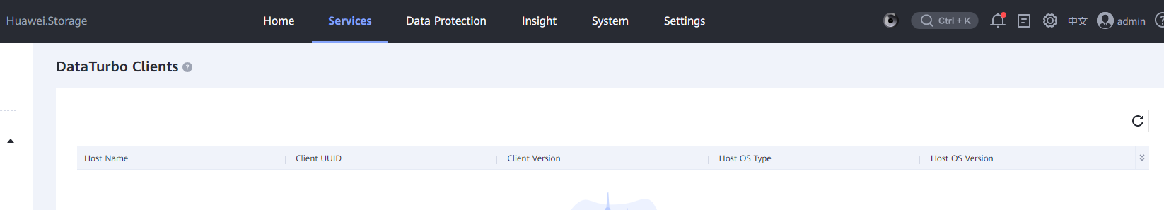
—-End
Establishing a Fibre Channel Link
Step 1 Run the dataturbo_rescan command to detect the mapping change of the channel LUN created in 4.4.2.4 Creating Channel LUNs on OceanProtect X8000 (DataTurbo over Fibre Channel).
In this example, delete sg xxxx indicates channel LUN mapping removal. scan hostx in the command output indicates new channel LUN mapping.
[root@localhost ~]# dataturbo_rescan
delete sg device sg2 sucess.
delete sg device sg3 sucess.
scan host1
scan host2
Step 2 Run the dataturbo create storage_object storage_name=name link_type=FC command (name indicates the user-defined storage name) to establish connection between the DataTurbo client and backup storage system.
Enter the username and password of the created DataTurbo user as prompted. If Create storage object successfully is displayed as shown in this example, the storage object is successfully created.
[root@localhost ~]# dataturbo create storage_object storage_name=test123 link_type=FC
Please input username:
test_001
Please input password:
**********
Create storage object successfully.
Step 3 Run the dataturbo show storage_object command to check whether the connection is established successfully.
In the following example, four Fibre Channel links are created on the backup storage. If Status is Normal, the connections are successful and the links are normal.
[root@localhost ~]# dataturbo show storage_object
Storage Name: test123
User : test_001
ID Initiator WWN Target WWN Status
—————————————————————
1 210000********c4 2800**********58 Normal
2 210000********c4 2801**********58 Normal
3 210000********c4 28b0**********3d Normal
4 210000********c4 28e0**********58 Normal
—-End
Mounting a File System
Step 1 Run the dataturbo mount storage_object storage_name=name filesystem_name=/fsname mount_dir=H: enable_user_security=false command to mount the file system created on the backup storage to the specified mount point.
name indicates the storage name defined in Establishing a TCP Link or Establishing a Fibre Channel Link. fsname indicates the name of the DataTurbo share path created in 4.4.2.5 Creating File Systems and Shares.
In the following example, the storage name is storage1, the file system name is testfile, and the mount point is H:.
C:\Users\Administrator>dataturbo mount storage_object storage_name=storage1 filesystem_name=/testfile mount_dir=H: enable_user_security=false
Command executed successfully.
Step 2 Run the dataturbo show mount_dir command to check whether the mounting is successful.
C:\Users\Administrator>dataturbo show mount_dir
StorageName FilesystemName MountPoint EnableUserSecurity
————————————————————————————————–
storage1 /testfile H: false
Step 3 Configure the mount point to be persistent. To ensure that the configured mount information is not lost after the backup server is restarted, configure the mount information in the …\oceanstor\DataTurbo\conf\dpc_mount_tab file in the installation path in the specified format. The following provides a configuration example, where file system /testfile, mount point H:, and the ACL configuration are separated by spaces.
# ———————————-Description———————————— #
# File system written in this config file will be automatically mounted to the
# mount directory when the operating system starts up. Remove the mount information
# from this file if you do not need it to be mounted automatically at the start.
#
# Config Format:
# filesystem_name mount_dir mount_option
# Example:
# /exampleFileSystem « E: » enable_user_security=false
# ——————————————————————————— #
/testfile « H: » enable_user_security=false
—-End
4.4.5 Configuring the NetWorker Backup Environment
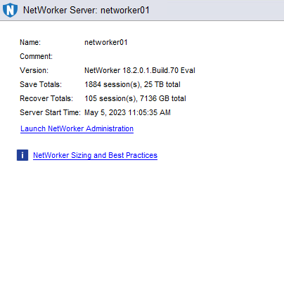
4.4.5.1 Logging In to the NetWorker WebUI
Step 1 Enter the management server IP address followed by port number 9000, and click Launch console.
Step 2 Enter the username and password for login.
Step 3 Click Launch NetWorker Administration to enter the WebUI.
—-End
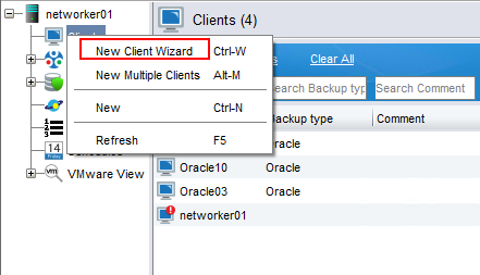
4.4.5.2 Configuring the Client
Step 1 Click Protection, right-click Clients, and select New Client Wizard from the shortcut menu to create a client.
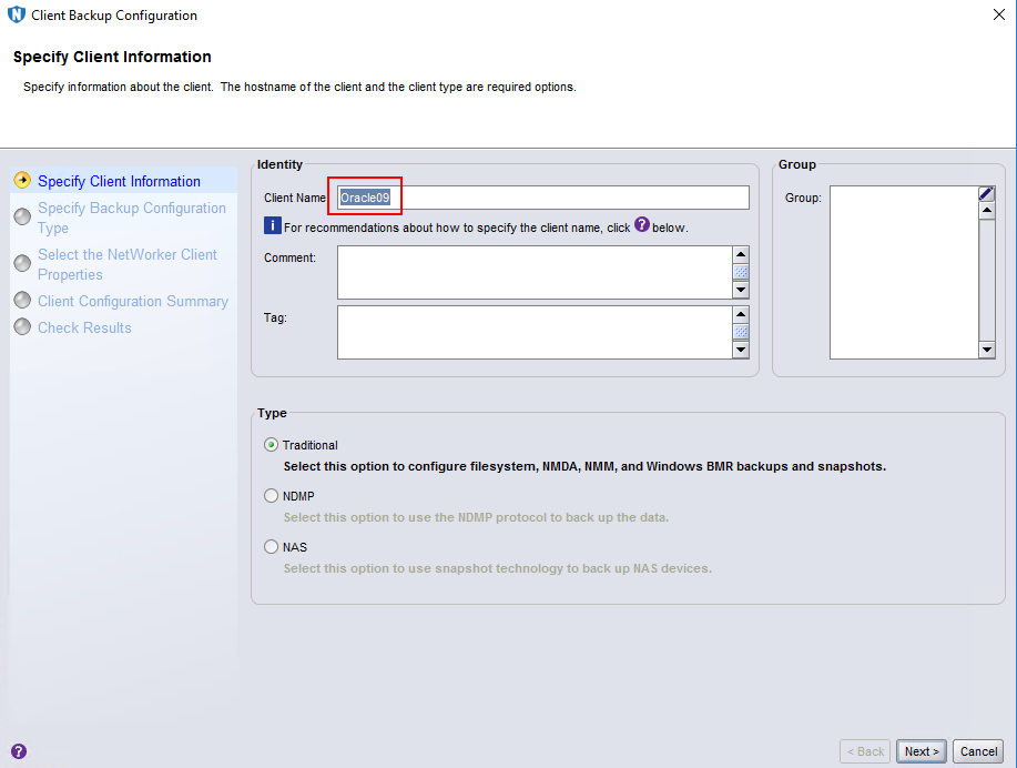
Step 2 On the Specify Client Information page, enter a client name and click Next.
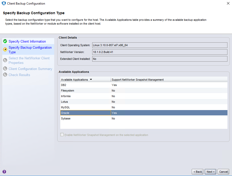
Step 3 On the Specify Backup Configuration Type page, set Available Applications to Oracle and click Next.
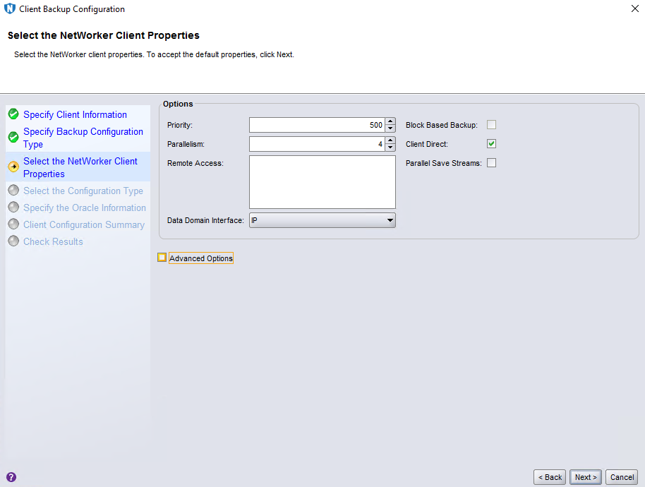
Step 4 Retain default settings on the Select the NetWorker Client Properties page and click Next.
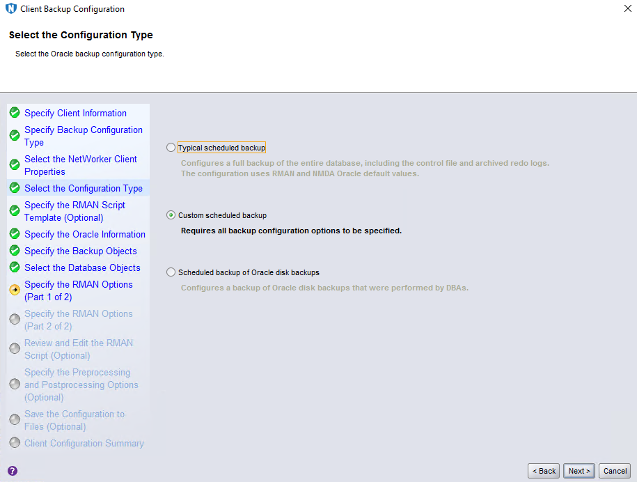
Step 5 On the Select the Configuration Type page, select Custom scheduled backup and click Next.
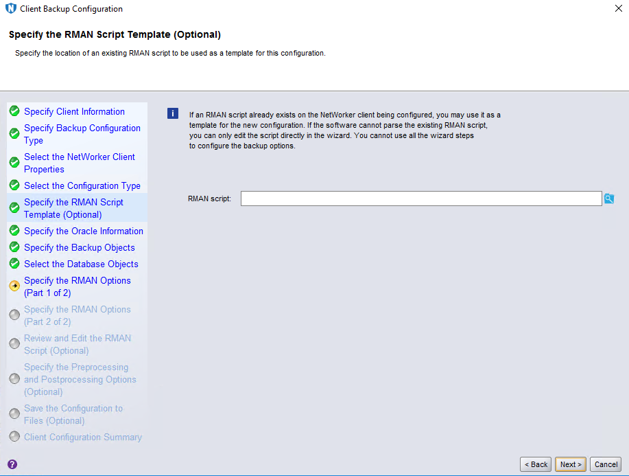
Step 6 Retain default settings on the Specify the RMAN Script Template (Optional) page and click Next.
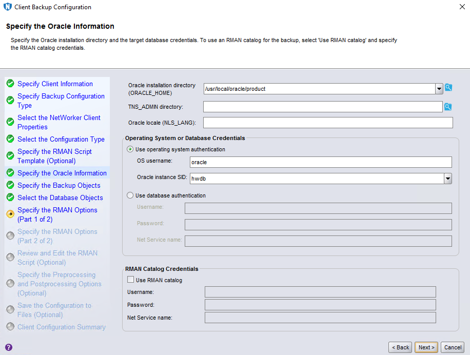
Step 7 On the Specify the Oracle Information page, set OS username and Oracle instance SID, and click Next.
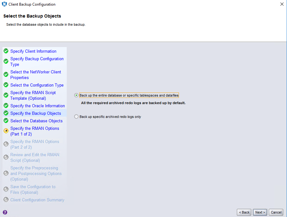
Step 8 Retain default settings on the Select the Backup Objects page and click Next.
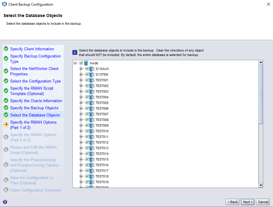
Step 9 On the Select the Database Objects page, select data sources to be backed up. By default, all options are selected. Then, click Next.
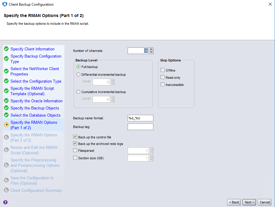
Step 10 On the Specify the RMAN Options (Part 1 of 2) page, set Number of channels based on the Oracle performance, set other parameters based on service requirements, and click Next.
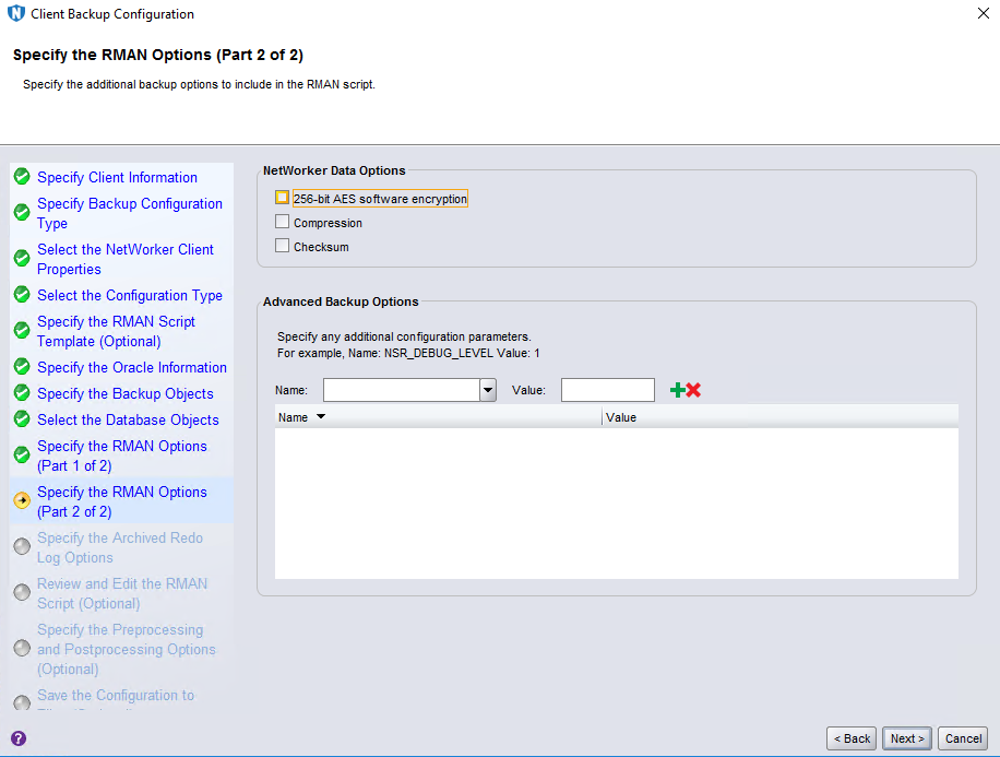
Step 11 Retain default settings on the Specify the RMAN Options (Part 2 of 2) page and click Next.
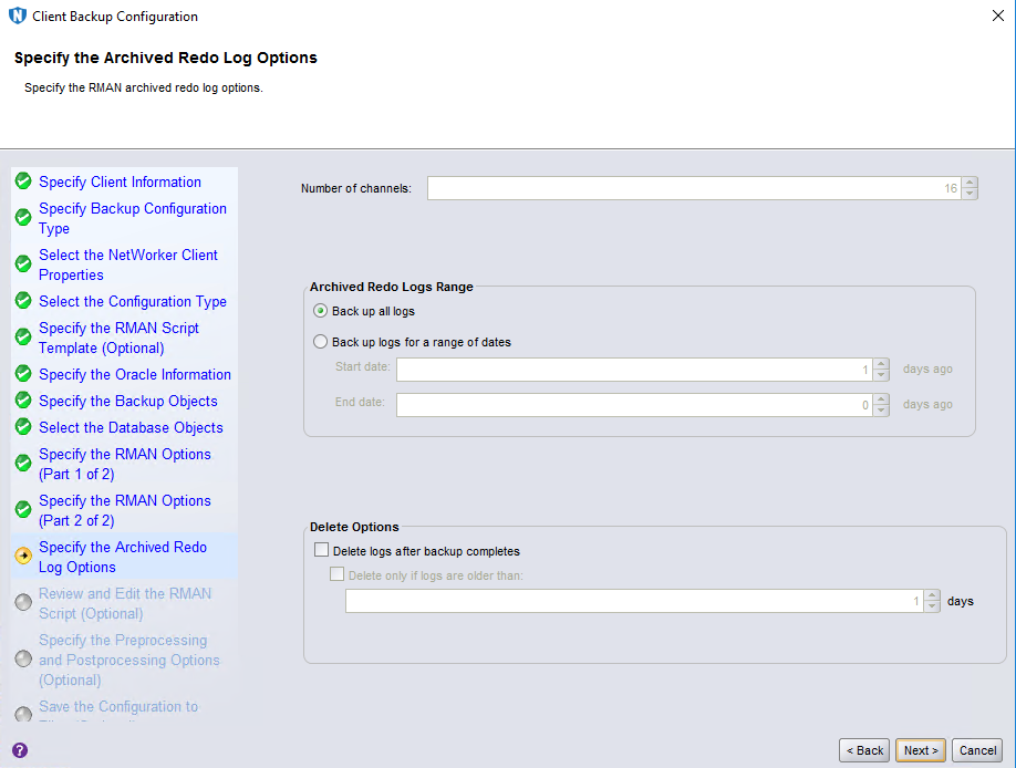
Step 12 Retain default settings on the Specify the Archived Redo Log Options page and click Next.
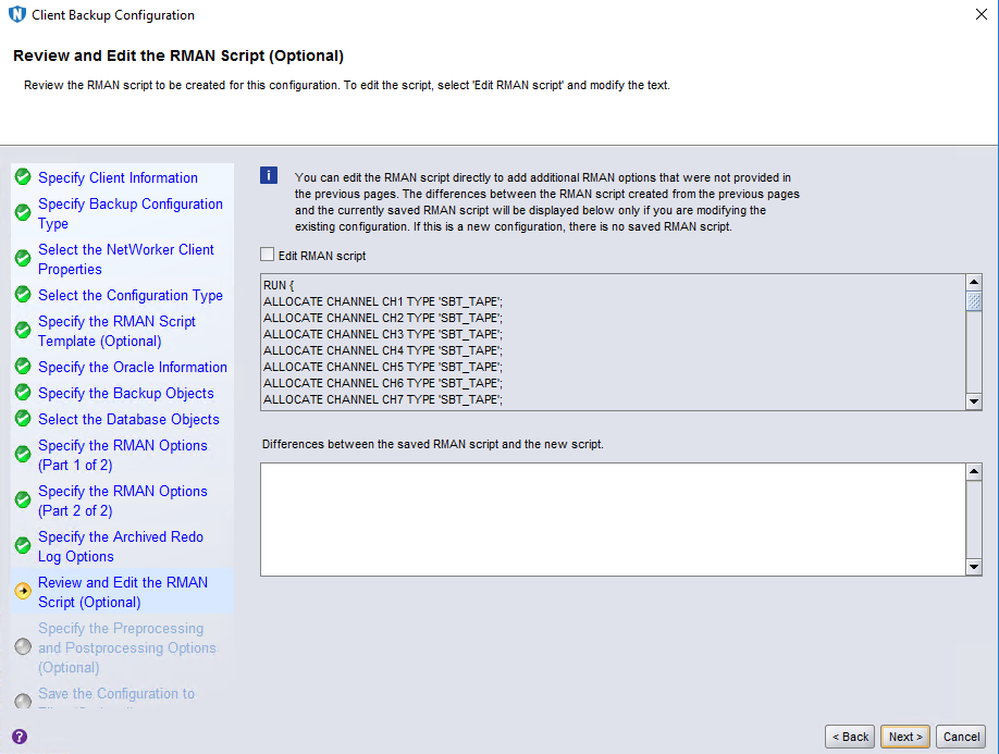
Step 13 Retain default settings on the Review and Edit the RMAN Script (Optional) page and click Next.
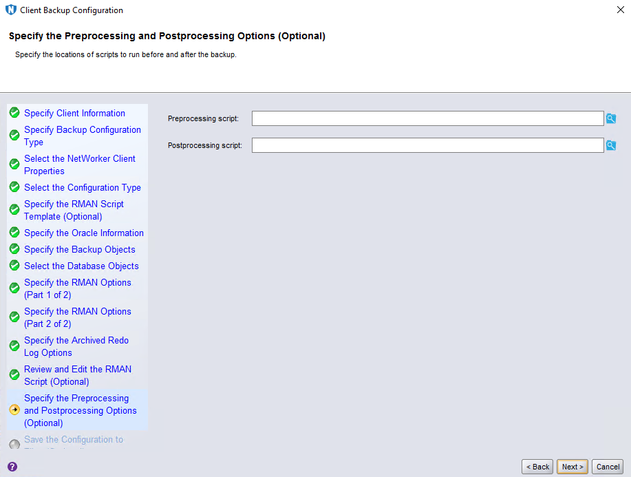
Step 14 Retain default settings on the Specify the Preprocessing and Postprocessing Options (Optional) page and click Next.
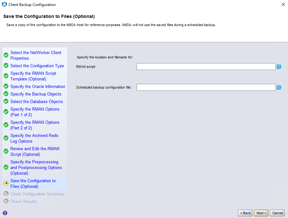
Step 15 Retain default settings on the Save the Configuration to Files (Optional) page and click Next.
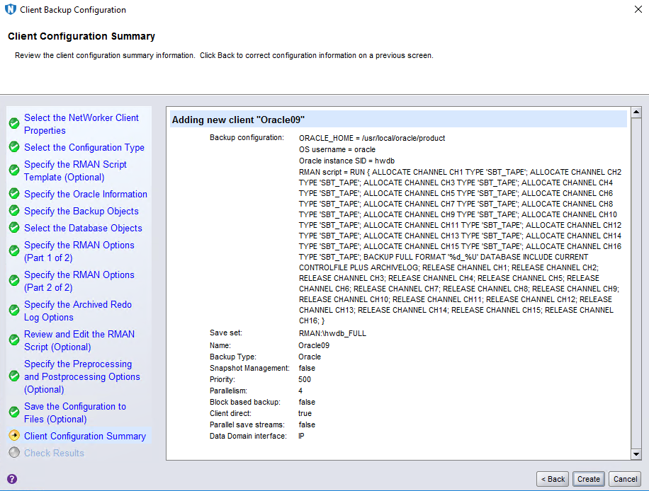
Step 16 On the Client Configuration Summary page, confirm the client information and click Create.
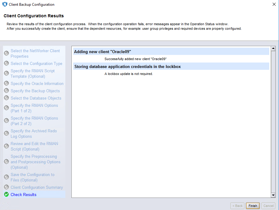
Step 17 On the Client Configuration Results page, click Finish.
—-End
4.4.5.3 Configuring the Group
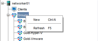
Step 1 Click Protection, right-click Groups, and select New from the shortcut menu to create a group.
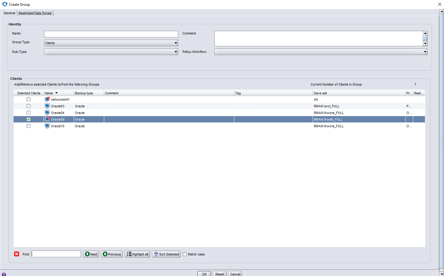
Step 2 Click the General tab on the Create Group page, set Name, select a client, and click OK.
—-End
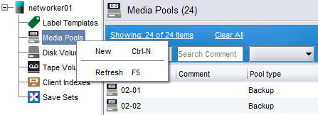
4.4.5.4 Configuring the Pool
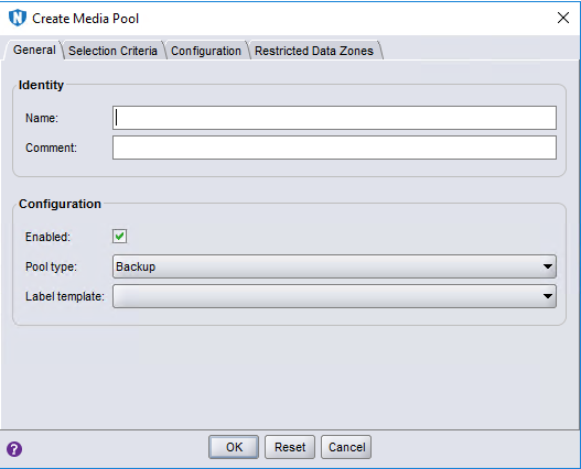
Step 1 Click Media, right-click Media Pools, and click New from the shortcut menu to create a pool.
Step 2 On the Create Media Pool page, specify Name, select a value for Label template, and click OK.
—-End
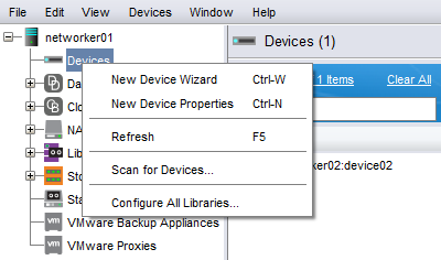
4.4.5.4 Configuring the Device
Step 1 Click Devices, right-click Devices, and click New Device Wizard from the shortcut menu to create a device.
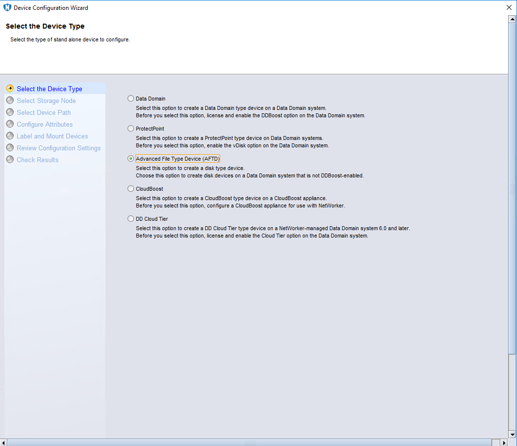
Step 2 On the Select the Device Type page, select Advanced File Type Device (AFTD).
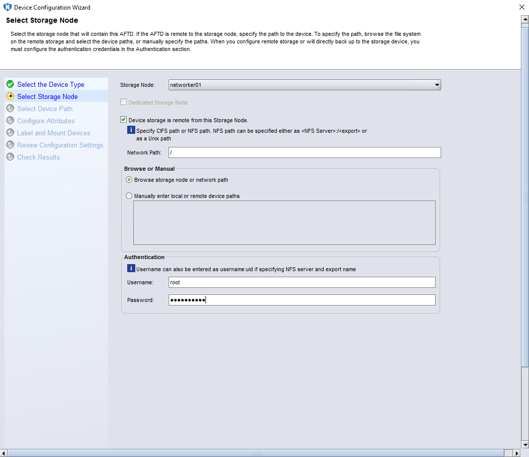
Step 3 (Optional) Perform this step only in the NFS or CIFS scenario. On the Select Storage Node page, select Device storage is remote from this Storage Node, enter the share address for Network Path, enter the OS username for Username, and enter the password for Password.
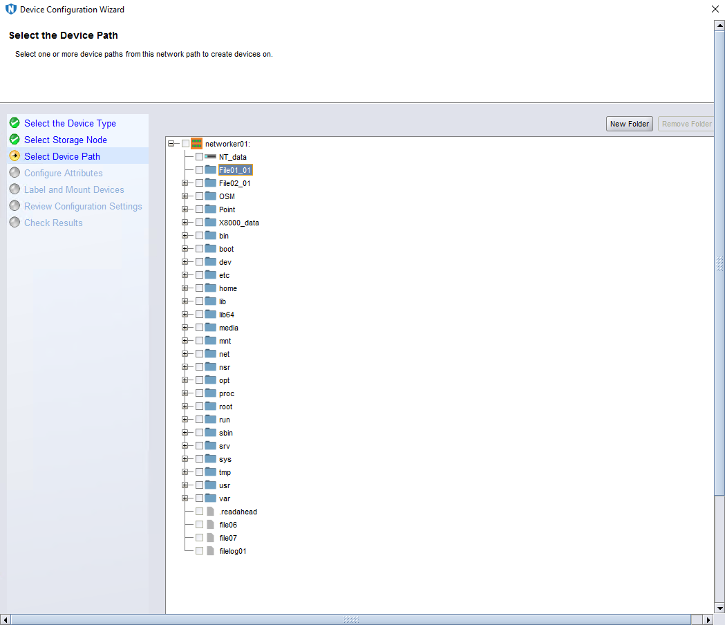
Step 4 On the Select the Device Path page, select the directory that OceanProtect X8000 mounts to the storage node.
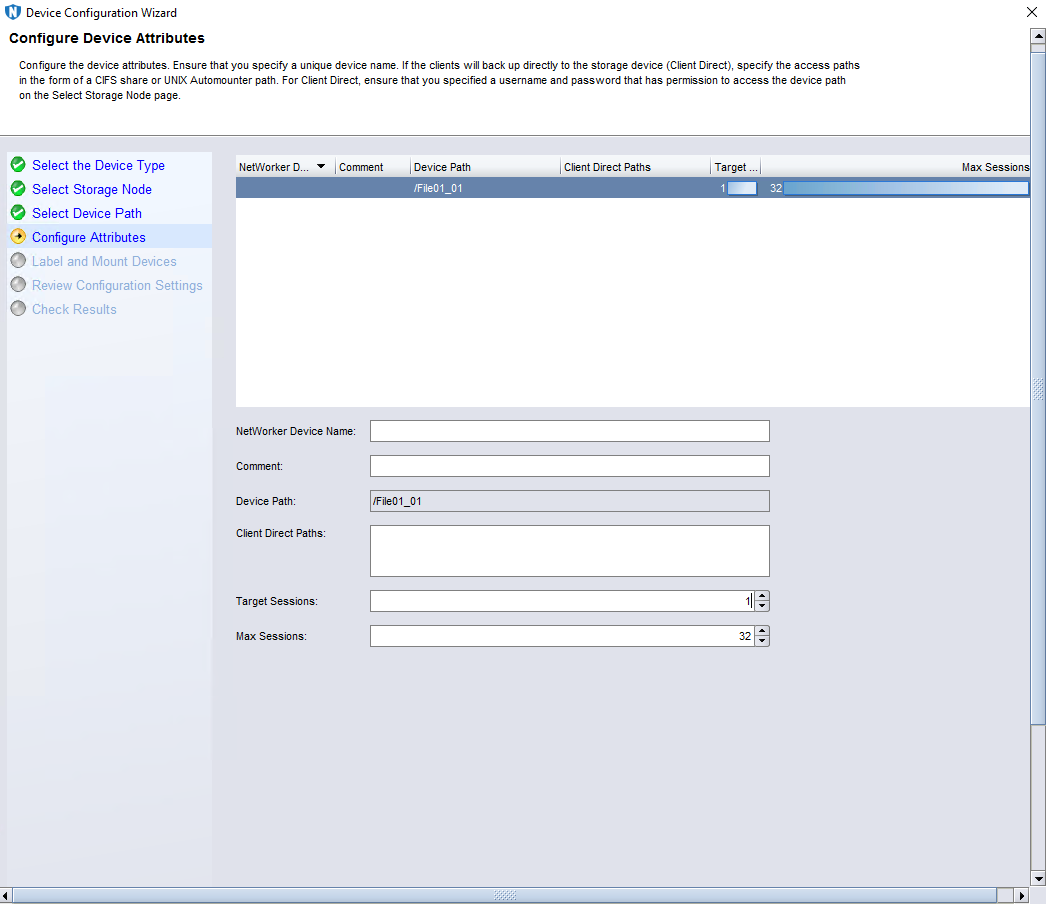
Step 5 On the Configure Device Attributes page, enter the device name in the NetWorker Device Name field, and set Target Sessions to 1.
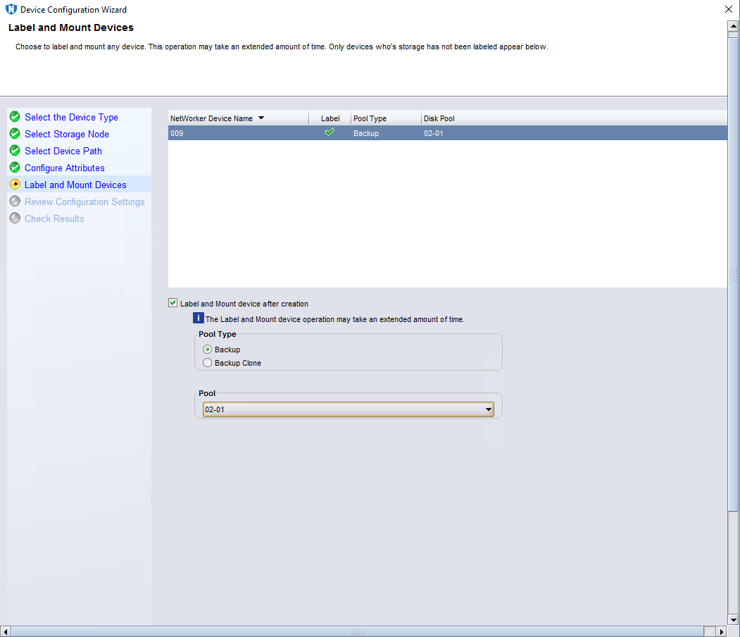
Step 6 On the Label and Mount Devices page, select the pool created in 4.4.5.4 Configuring the Pool.
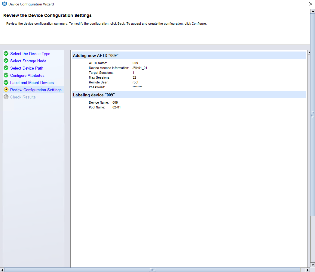
Step 7 On the Review the Device Configuration Settings page, confirm the device configuration information, and click Configure.
—-End
4.4.5.6 Configuring the Policy
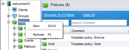
Step 1 Click Protection, right-click Policies, and select New from the shortcut menu to create a policy.
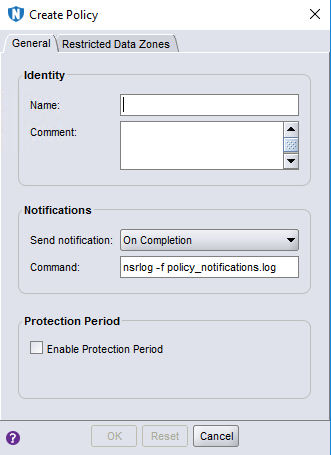
Step 2 On the Create Policy page, enter a policy name, and click OK.
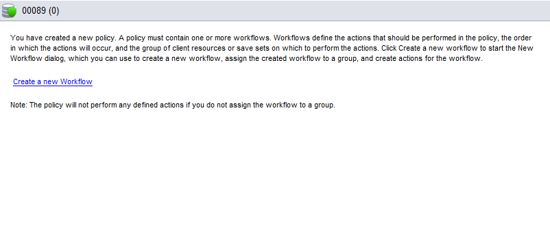
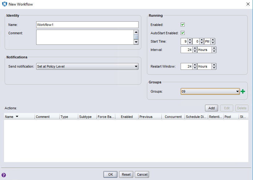
Step 3 Click Create a new Workflow.
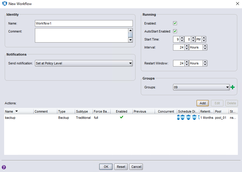
Step 4 On the New Workflow page, enter a workflow name, select a value for Groups, and click Add.
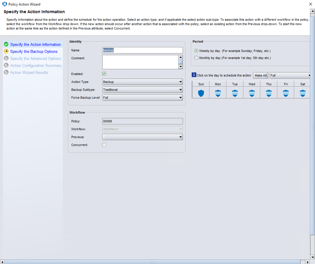
Step 5 On the Specify the Action Information page, specify Name, and set Force Backup Level to Full for full backup.
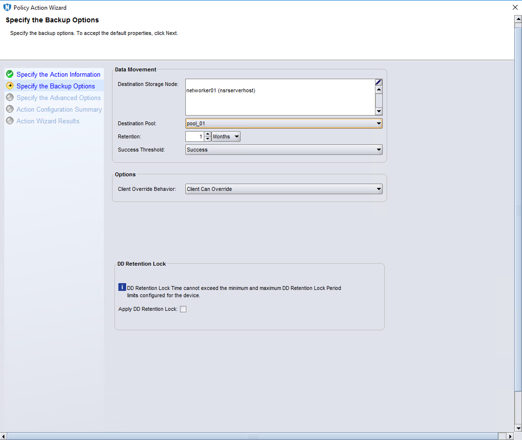
Step 6 On the Specify the Backup Options page, select a destination pool.
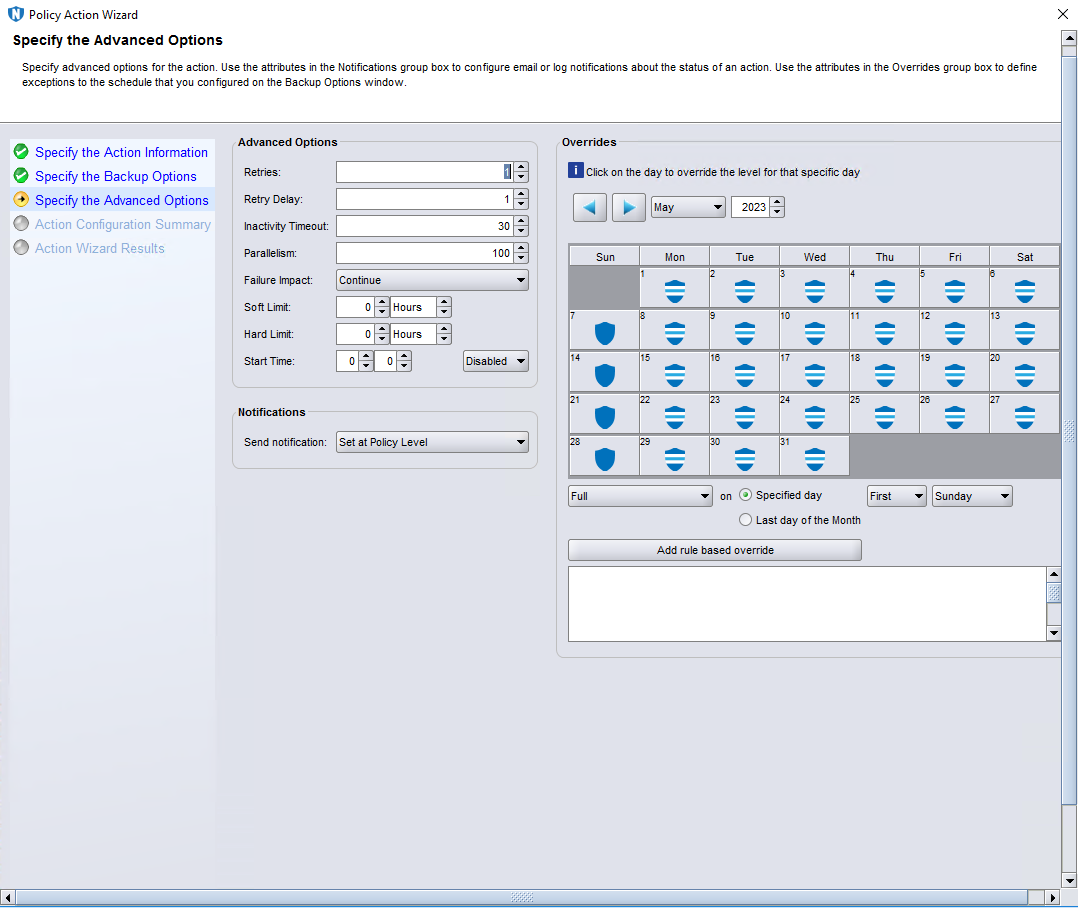
Step 7 Retain default settings on the Specify the Advanced Options page.
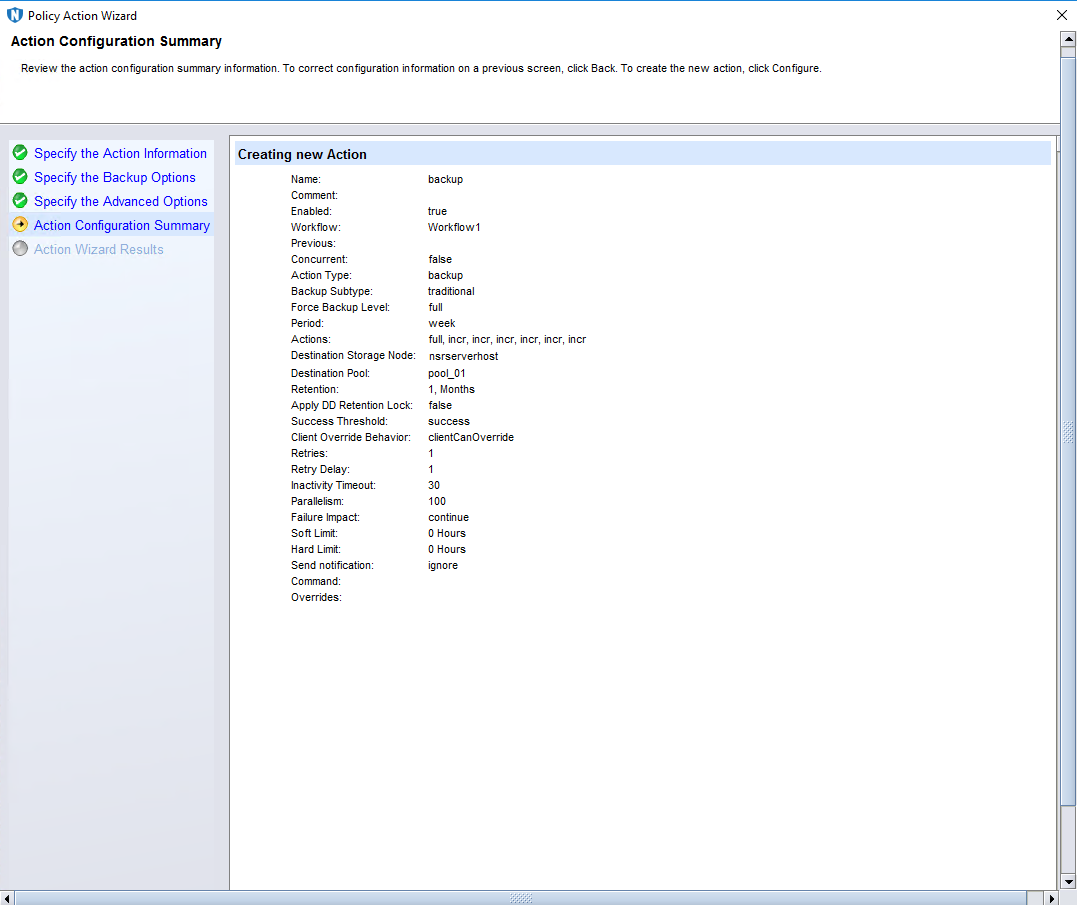
Step 8 On the Action Configuration Summary page, confirm the configuration information, and click Configure.
Step 9 On the New Workflow page, click OK.
—-End
4.4.6 Executing Backup
Step 1 Select the created policy, right-click the workflow, and click Start from the shortcut menu.
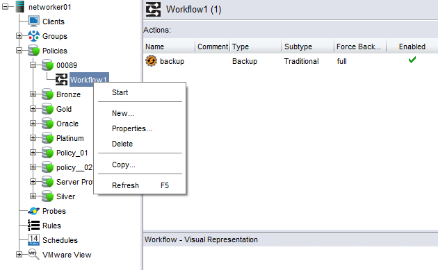
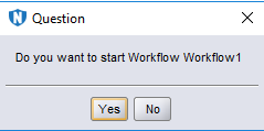
Step 2 Click Yes to start backup.
—-End
4.4.7 Executing Restoration
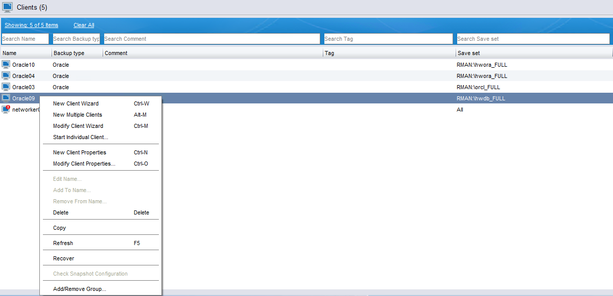
Step 1 On the Protection > Clients page, right-click the desired client, and click Recover from the shortcut menu.
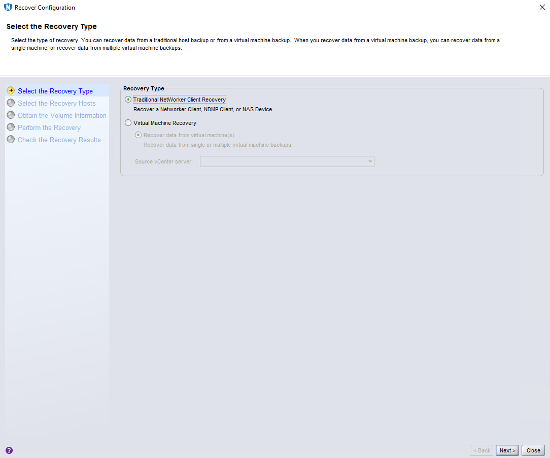
Step 2 On the Select the Recovery Type page, select Traditional NetWorker Client Recovery (default) and click Next.
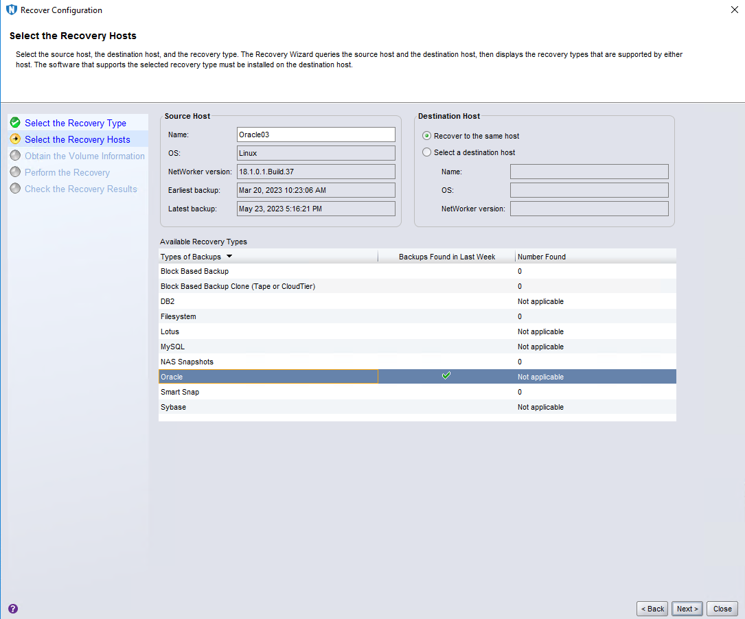
Step 3 On the Select the Recovery Hosts page, select Oracle under Available Recovery Types and click Next.
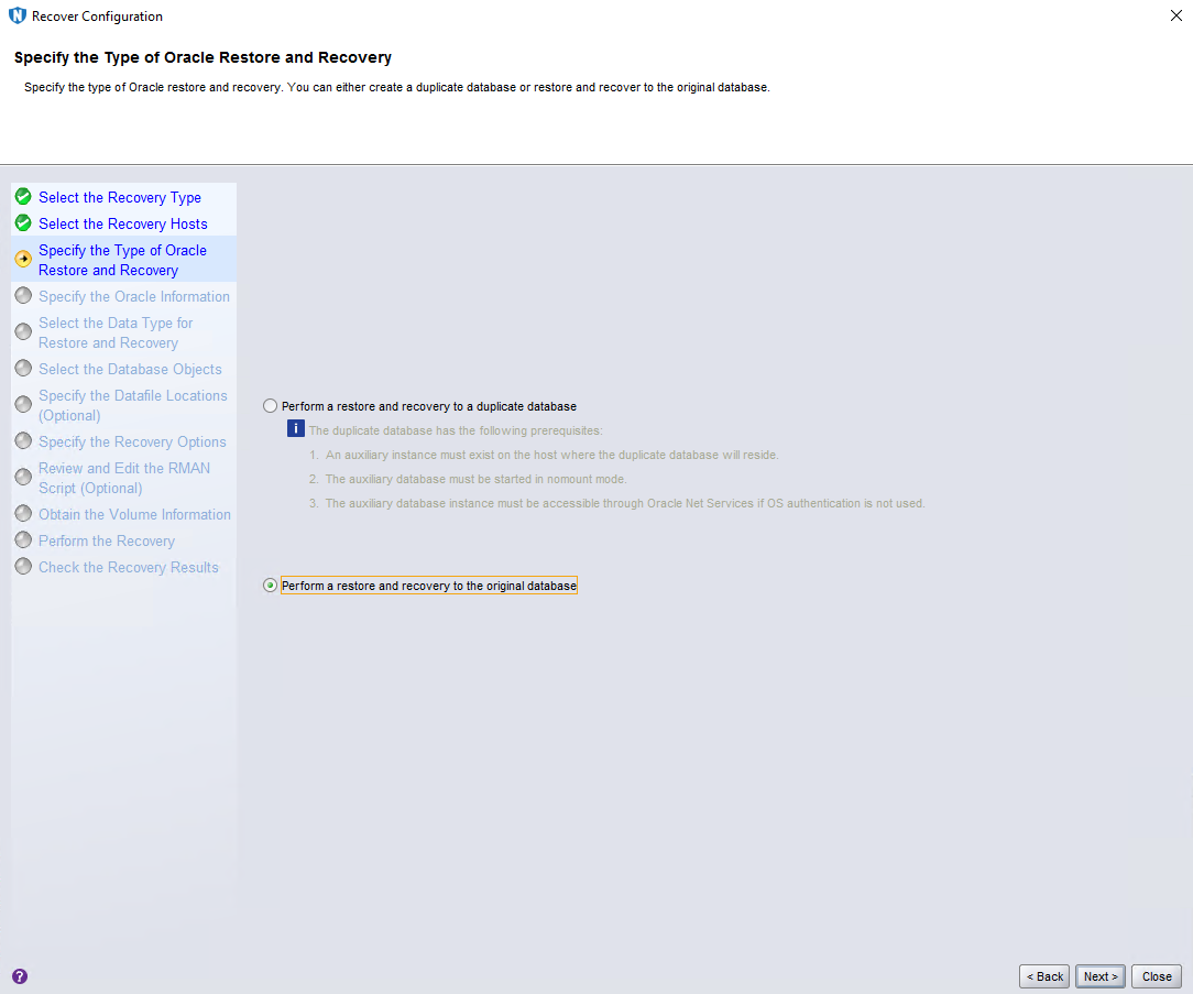
Step 4 On the Specify the Type of Oracle Restore and Recovery page, select Perform a restore and recovery to the original database and click Next.
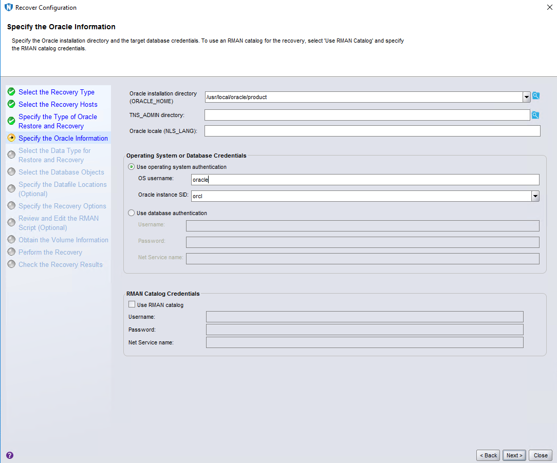
Step 5 On the Specify the Oracle Information page, enter oracle for OS username. Click Next.
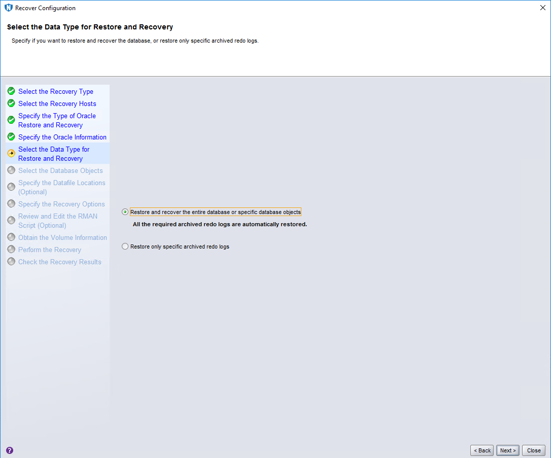
Step 6 Retain default settings on the Select the Data Type for Restore and Recovery page and click Next.
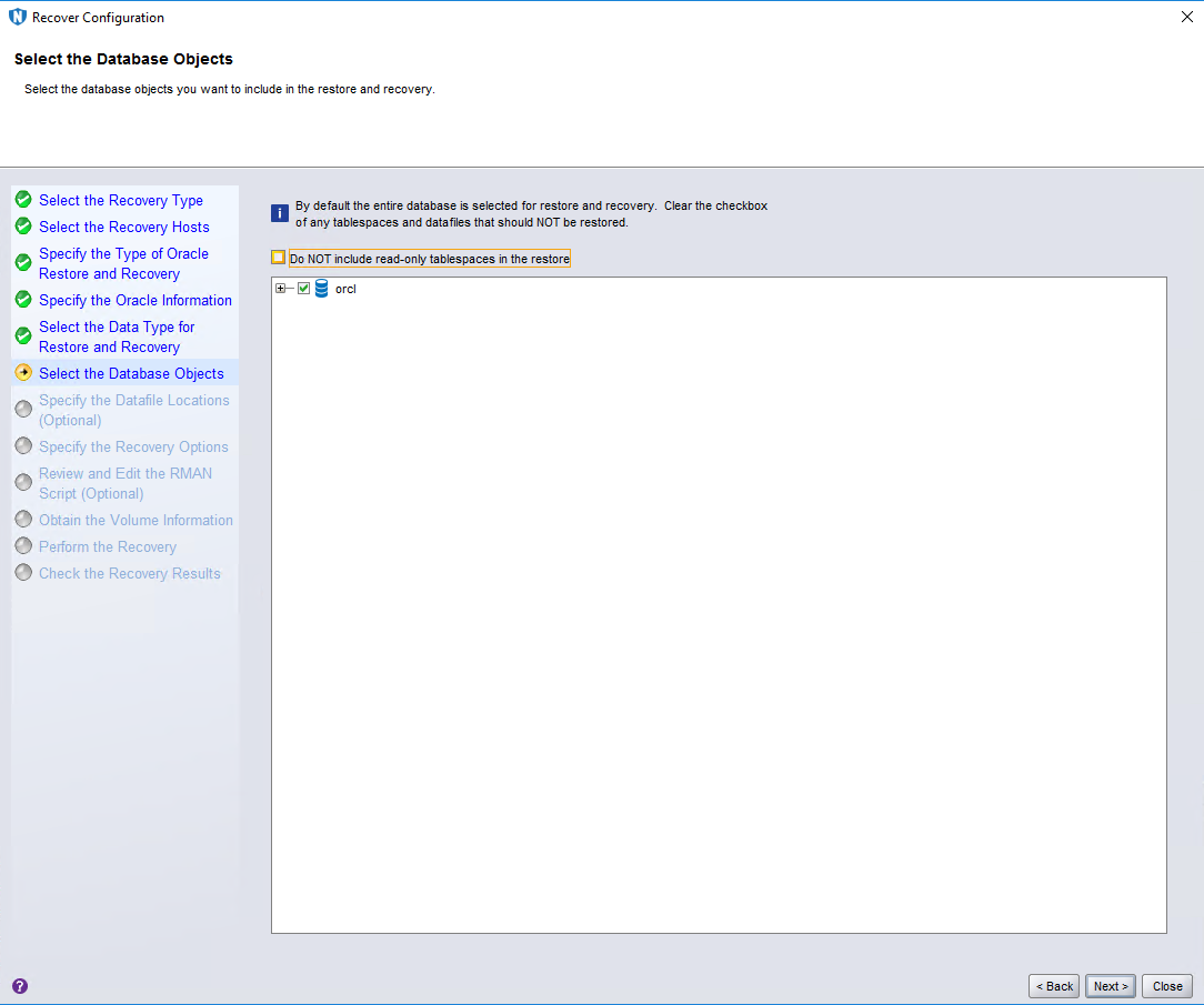
Step 7 On the Select the Database Objects page, select the data to be restored and click Next.
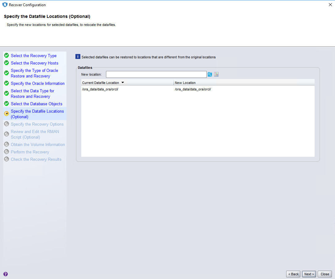
Step 8 Retain default settings on the Specify the Datafile Locations (Optional) page and click Next.
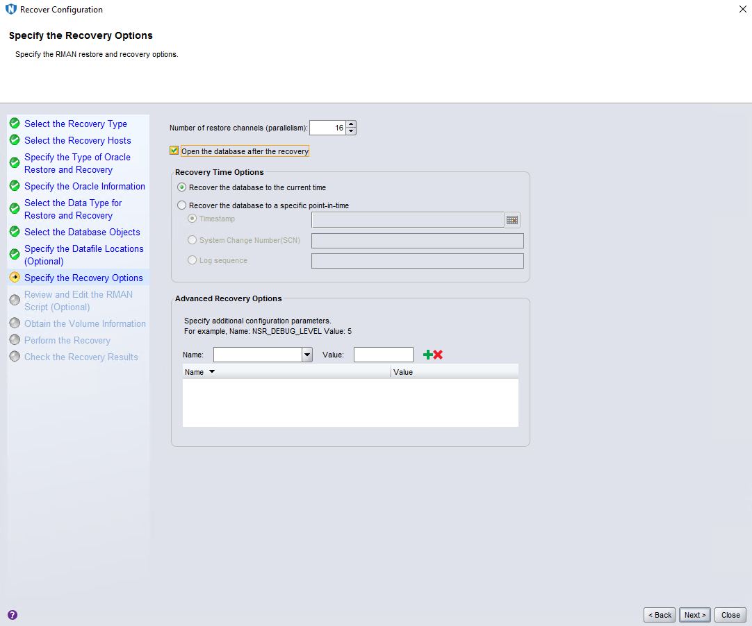
Step 9 On the Specify the Recovery Options page, set Number of restore channels (parallelism) based on Oracle performance, and select Open the database after the recovery. After the restoration is successful, the Oracle database will be automatically opened. Click Next.
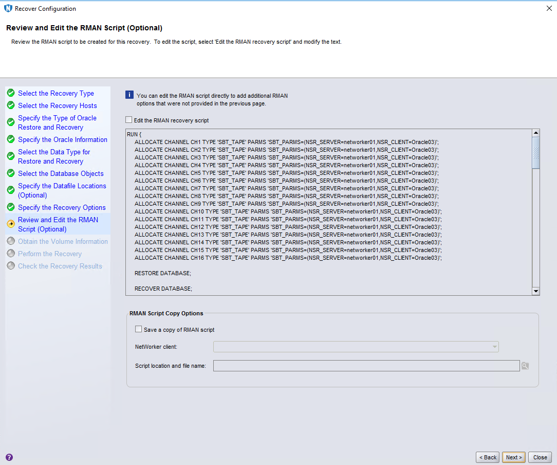
Step 10 Retain default settings on the Review and Edit the RMAN Script (Optional) page and click Next.
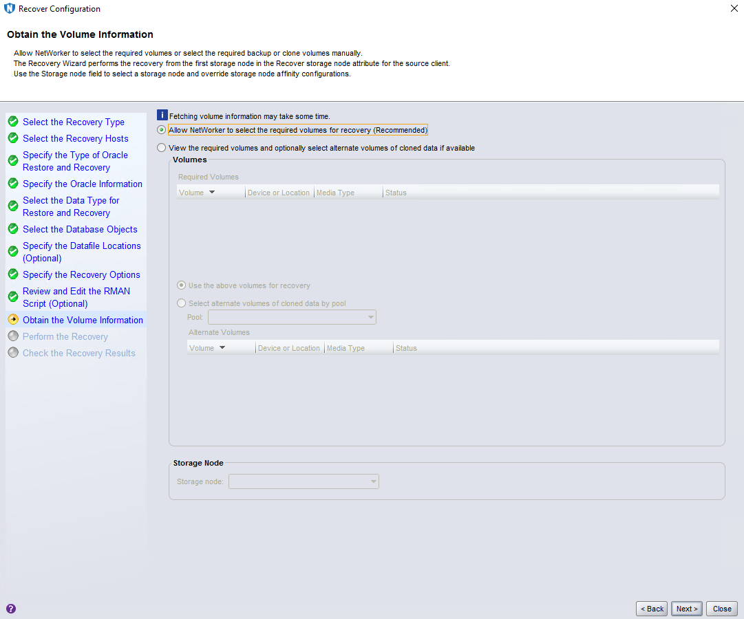
Step 11 Retain default settings on the Obtain the Volume Information page and click Next.
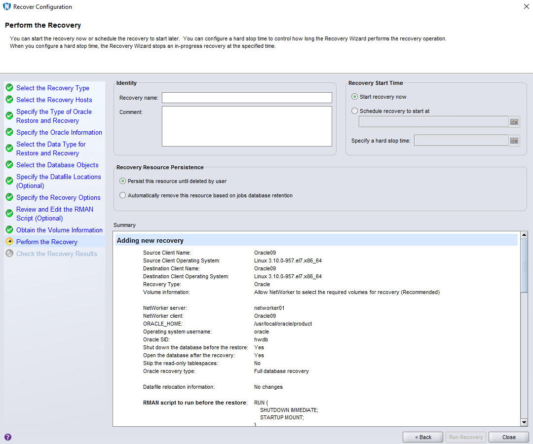
Step 12 On the Perform the Recovery page, set Recovery name and click Run Recovery.
—-End
4.5 Configuring the Remote Replication Environment
4.5.1 Configuring Remote Replication
4.5.1.1 Creating Replication Logical Ports
In this practice, OceanProtect X8000 provides two physical ports used for replication links. Each physical port is configured with one replication logical port. A total of two replication logical ports are created. Use the same method to configure logical ports on the local and remote devices. The following is an example of configuring logical ports:
Step 1 Log in to DeviceManager of the remote device.
Step 2 Choose Services > Network > Logical Ports.
Step 3 Select All vStores from the vStore drop-down list. Click Create. On the Create Logical Port page that is displayed, set Role to Replication, enter key information such as the IP address, and set Port Type and Home Port based on the planned physical ports used for replication.
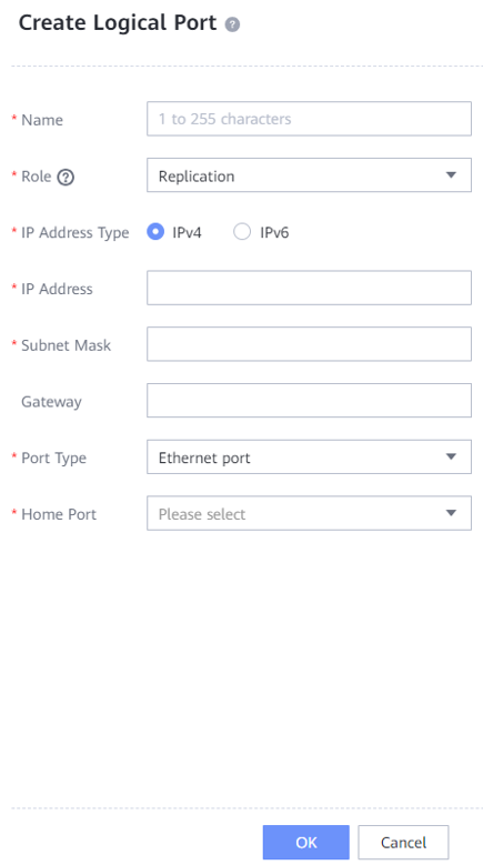
—-End
4.5.1.2 Creating a Remote Device Administrator
Step 1 Log in to DeviceManager of the remote device.
Step 2 Choose Settings > User and Security > Users and Roles > Users.
Step 3 Click Create. On the Create User page that is displayed, set Role to Remote device administrator, enter the username and password, and click OK to create a remote device administrator.
The following figure shows a configuration example.
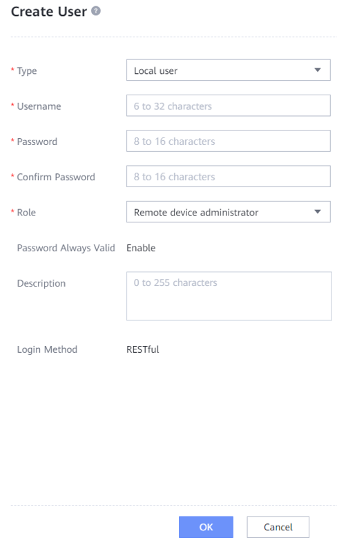
—-End
4.5.1.3 Creating a Remote Device
Step 1 Log in to DeviceManager of the local device.
Step 2 Choose Data Protection > Remote Devices.
Step 3 Click . The Add Remote Device page is displayed.

Set Link Type to IP link, and set Local Port, Remote IP Address, Remote Device Administrator, and Password. Then, click Connect.
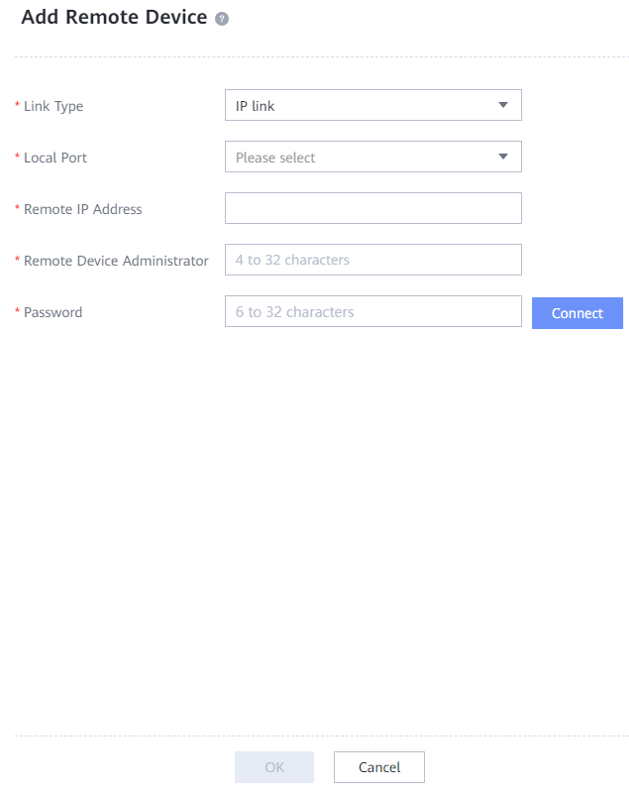
—-End
4.5.2 Creating Remote Replication
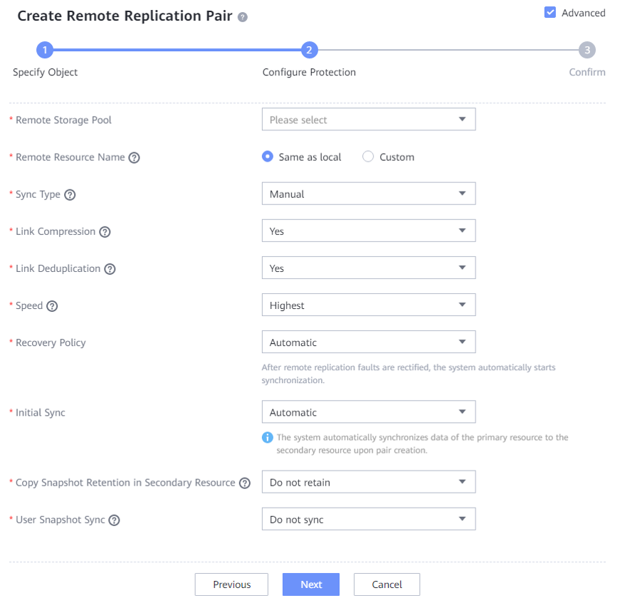
Step 1 Log in to DeviceManager of the local device. Choose Data Protection > Remote Replication > File Systems, and click Create. On the Create Remote Replication Pair page that is displayed, select file systems for which you want to create a remote replication pair, and click Next.
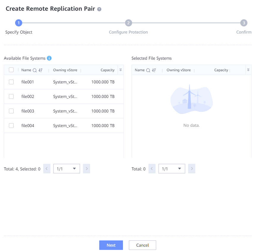
Step 2 On the Configure Protection page, select Advanced. Set Link Compression to Yes, Link Deduplication to Yes, and Speed to Highest. Retain default settings of other parameters.
—-End
4.6 Best Practice Verification Examples
4.6.1 Backup Performance of a Single Storage Node (DataTurbo over TCP Networking)
In this solution, a typical server (CPU: Intel(R) Xeon(R) Silver 4214R; memory: 128 GB) is used to test backup performance of Oracle database backup using a single Storage Node. The test information is as follows:
Test scenario:
- Production environment: A single Storage Node is used to back up two Oracle hosts. Each Oracle host is preconfigured with 45 to 70 data files. The size of each data file ranges from 35 GB to 45 GB. The size of each database ranges from 1.7 TB to 2.1 TB. The total data volume of the two Oracle databases is about 5 TB.
- Backup environment: OceanProtect X8000 (all-flash form) is used to create file systems, and connects to one Storage Node through DataTurbo over an IP network.
- Test model: Test the initial, second, and third full backups with 5% data changed each time. Table 4-3 shows bandwidth performance when a single Storage Node is used.
Table 4-3 Backup bandwidth performance test results when a TCP network is used
|
Compression Mode |
Backup Type |
Peak Backup Bandwidth (GB/s) |
Backup Data Volume (GB) |
Backup Duration (Minutes) |
Average Backup Bandwidth (GB/s) |
|---|---|---|---|---|---|
|
High performance mode |
Initial backup |
2.268 |
4209 |
37 |
1.896 |
|
Second backup |
2.916 |
4209 |
34 |
2.063 | |
|
Third backup |
3.039 |
4209 |
33 |
2.126 | |
|
High reduction ratio mode |
Initial backup |
1.605 |
4209 |
51 |
1.375 |
|
Second backup |
2.935 |
4209 |
33 |
2.126 | |
|
Third backup |
2.980 |
4209 |
34 |
2.063 |
4.6.2 Restoration Performance of a Single Storage Node (DataTurbo over TCP Networking)
Table 4-4 shows the test results of restoring two Oracle hosts using a single Storage Node server.
Table 4-4 Restoration bandwidth performance test results when a TCP network is used
|
Compression Mode |
Number of Oracle Hosts |
Peak Restoration Bandwidth (GB/s) |
Restored Data Volume (GB) |
Restoration Duration (Minutes) |
Average Restoration Bandwidth (GB/s) |
|---|---|---|---|---|---|
|
High performance mode |
2 |
1.842 |
4029 |
48 |
1.461 |
|
High reduction ratio mode |
2 |
1.783 |
4209 |
48 |
1.461 |
4.6.3 Backup Performance of a Single Storage Node (DataTurbo over Fibre Channel Networking)
In this solution, a typical server (CPU: Intel(R) Xeon(R) Silver 4214R; memory: 128 GB) is used to test backup performance of Oracle database backup using a single Storage Node. The test information is as follows:
Test scenario:
- Production environment: A single Storage Node is used to back up two Oracle hosts. Each Oracle host is preconfigured with 45 to 70 data files. The size of each data file ranges from 35 GB to 45 GB. The size of each database ranges from 1.7 TB to 2.1 TB. The total data volume of the two Oracle databases is about 5 TB.
- Backup environment: OceanProtect X8000 (all-flash form) is used to create file systems and is connected to one Storage Node through DataTurbo over a Fibre Channel network.
- Test model: Test the initial, second, and third full backups with 5% data changed each time. Table 4-5 shows bandwidth performance when a single Storage Node is used.
Table 4-5 Backup bandwidth performance test results when a Fibre Channel network is used
|
Compression Mode |
Backup Type |
Peak Backup Bandwidth (GB/s) |
Backup Data Volume (GB) |
Backup Duration (Minutes) |
Average Backup Bandwidth (GB/s) |
|---|---|---|---|---|---|
|
High performance mode |
Initial backup |
1.935 |
4796 |
63 |
1.262 |
|
Second backup |
3.096 |
4796 |
49 |
1.622 | |
|
Third backup |
3.047 |
4796 |
58 |
1.370 | |
|
High reduction ratio mode |
Initial backup |
1.407 |
4209 |
51 |
1.375 |
|
Second backup |
2.851 |
4209 |
41 |
1.711 | |
|
Third backup |
2.808 |
4209 |
41 |
1.711 |

The high performance mode and high reduction ratio mode in Table 4-5 are described as follows:
- High performance mode: When the storage pool compression mode is set to high performance mode, set the file system application type to Performance_Prioritized_Mode_enhanced.
- High reduction ratio mode: When the storage pool compression mode is set to high reduction ratio mode, set the file system application type to Reduction_Prioritized_Mode_enhanced.
4.6.4 Restoration Performance of a Single Storage Node (DataTurbo over Fibre Channel Networking)
Table 4-6 shows the test results of restoring two Oracle hosts using a single Storage Node server.
Table 4-6 Restoration bandwidth performance test results when a Fibre Channel network is used
|
Compression Mode |
Number of Oracle Hosts |
Peak Restoration Bandwidth (GB/s) |
Restored Data Volume (GB) |
Restoration Duration (Minutes) |
Average Restoration Bandwidth (GB/s) |
|---|---|---|---|---|---|
|
High performance mode |
2 |
1.946 |
4302 |
47 |
1.526 |
|
High reduction ratio mode |
2 |
1.905 |
4209 |
46 |
1.525 |
4.6.5 Backup Performance Test Results when Multiple Backup Media Servers Are Used
Two Storage Nodes (CPU: Intel(R) Xeon(R) Silver 4214R; memory: 128 GB) with the same configurations are used. On OceanProtect X8000, the high performance mode is used. Performance is tested when one or two Storage Nodes are used for Oracle database backup over a DataTurbo over Fibre Channel network. The backup performance increases linearly as the number of Storage Nodes increases. Table 4-7 shows the test data.
Table 4-7 Data reduction test results
|
Number of Backup Media Servers |
Backup Bandwidth (GB/s) |
|---|---|
|
1 |
3.096 |
|
2 |
5.366 |
4.6.6 Remote Replication Test Results
Two OceanProtect X8000 devices are used for remote replication.
- Networking: Two 10GE network cables are used for connection to the same switch to form a replication network. Then, a remote device is created.
- Remote replication configuration: Deduplicated and compressed replication is supported, and the speed is set to highest.
- Backup data difference: 5% data changes between two backups.
Table 4-8 lists the test results.
Table 4-8 Test results of the replication link data reduction ratio
|
Backup Type |
Data Volume (TB) |
Replication Link Data Reduction Ratio |
Replication Duration (Minutes) |
Average Bandwidth (GB/s) |
|---|---|---|---|---|
|
First remote replication |
1.752 |
2.801:1 |
15 |
1.993 |
|
Second remote replication |
1.752 |
185.684:1 |
5 |
5.980 |
|
Third remote replication |
1.752 |
197.303:1 |
5 |
5.980 |