OceanProtect 1.5.0 Backup Storage Solution Best Practice (Integration with Veeam Backup & Replication)

Overview
This document describes the best practice of backing up VMware vSphere’s data using OceanProtect X8000 and Veeam Backup & Replication 12.
Intended Audience
This document is intended for technical support engineers who must:
- Be familiar with the current network and version information about related NEs.
- Be experienced in operating and maintaining the device.
Symbol Conventions
The symbols that may be found in this document are defined as follows.
Symbol | Description |
|---|---|
 | Indicates a hazard with a high level of risk which, if not avoided, will result in death or serious injury. |
 | Indicates a hazard with a medium level of risk which, if not avoided, could result in death or serious injury. |
 | Indicates a hazard with a low level of risk which, if not avoided, could result in minor or moderate injury. |
 | Indicates a potentially hazardous situation which, if not avoided, could result in equipment damage, data loss, performance deterioration, or unanticipated results. NOTICE is used to address practices not related to personal injury. |
 | Supplements the important information in the main text. NOTE is used to address information not related to personal injury, equipment damage, and environment deterioration. |
Change History
Issue | Date | Description |
|---|---|---|
01 | 2023-01-30 | This issue is the first official release. |
1 Solution Overview
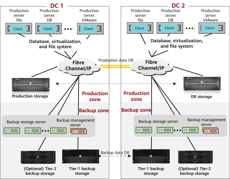
The backup storage solution provides a backup system with software and hardware deployed independently. It includes the backup software, backup agent, backup management server, backup storage server, and backup storage. As shown in Figure 1-1, the backup storage solution has a three-layer architecture: backup management server, backup storage server (backup media), and backup storage.
Figure 1-1 Architecture of the backup storage solution
2 Solution Introduction
2.1 Solution Components
2.1.1 OceanProtect backup storage
Service Positioning
As the amount, types, and growth rate of data change exponentially, enterprises face increasing data loss risks due to human errors, viruses, natural disasters, and Cyber resilience threats. Therefore, data protection becomes increasingly important.
OceanProtect backup storage features rapid backup, rapid restoration, efficient reduction, and solid resilience. It implements efficient backup and restoration with the TCO greatly reduced. It is widely used in government, finance, carrier, healthcare, and manufacturing industries. In addition, it offers easy management and convenient local/remote maintenance, significantly reducing device management and maintenance costs.
OceanProtect backup storage is available in solid-state drive (SSD) and hard disk drive (HDD) forms.
- SSD form: The system supports only SSDs. Service data and metadata are stored on SSDs.
- HDD form: The system supports SSDs and HDDs. Service data is stored on a storage pool composed of HDDs. SSDs only store system metadata. SSDs delivering higher performance accelerate metadata access, improving read and write performance.
Product Highlights
With the active-active high-reliability architecture and full-process acceleration, OceanProtect backup storage features rapid backup, rapid restoration, efficient reduction, and solid resilience.
- Rapid backup and restoration
- Full-process acceleration is implemented. The front-end network protocol offload technology reduces the CPU pressure, and back-end CPU multi-core parallel scheduling is implemented. Dedicated cores are used through grouping and task partitioning, efficiently improving the processing capability of nodes.
- Based on backup service characteristics, multiple sequential data flows are aggregated for read and write, greatly improving bandwidth performance. Source deduplication reduces the amount of data to be transmitted over the network, shortening the backup duration.
- The system provides high IOPS performance and can work with mainstream backup software. Backup image data can be accessed instantly, enabling fast utilization of backup data.
- Efficient reduction
- Accurate backup data segmentation, backup data aggregation preprocessing, and multi-layer inline variable-length deduplication are used to increase the logical capacity and reduce the total cost of operations (TCO).
- Data flow features can be identified. Combination-based compression, high-performance predictive encoding, and byte-level compaction are used to improve the data reduction ratio.
- Source deduplication and deduplicated replication are used to reduce network bandwidth costs.
- Solid resilience
- The active-active redundant hardware architecture design ensures that ongoing backup jobs, if a controller is faulty, can be switched over in seconds without being interrupted.
- Protocol encryption, replication link encryption, storage encryption, secure snapshot, and WORM functions are used to ensure security and availability of copies.
- Source deduplication
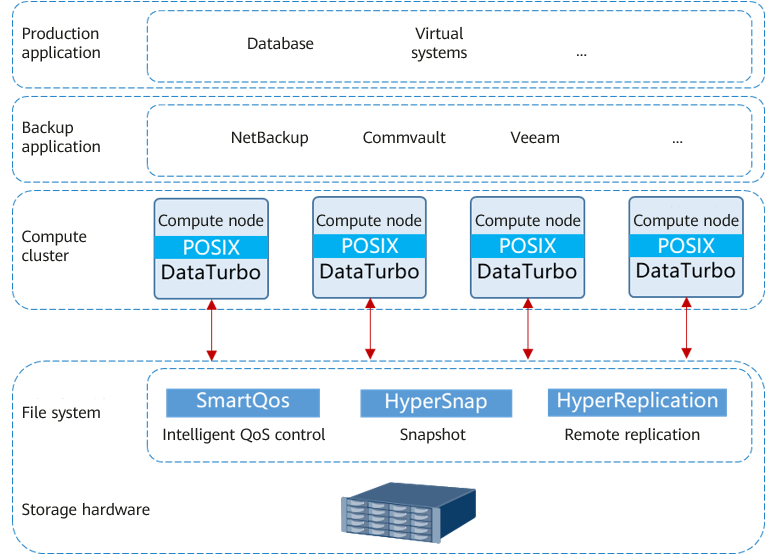
The DataTurbo client runs on a compute node and functions as a storage client. It exchanges data with back-end storage nodes through network protocols.
Compatible with standard POSIX semantics, the DataTurbo client provides data cache algorithms and source deduplication and compression algorithms, enabling upper-layer applications to access storage devices more efficiently. Figure 2-1 shows the position of the DataTurbo client in the backup solution.
Figure 2-1 Position DataTurbo in the backup solution.
2.1.2 Veeam Backup & Replication Backup Software
Veeam Backup & Replication provides data protection and disaster recovery solutions. It allows you to back up and restore applications such as VMs, file systems, and databases.
The basic architecture of Veeam is as follows.
- Backup server: Veeam Backup & Replication is installed on the backup server. As the core component of the backup infrastructure, the backup server is responsible for performing all types of administrative activities, such as coordinating backup, replication, recovery verification, and restore tasks, controlling job scheduling and resource allocation, and setting and managing backup infrastructure components. In addition, the backup server also serves as the default backup proxy and the backup repository.
- Backup proxy: It operates as a data mover that transfers data between the source file and the backup repository. It also processes backup jobs and delivers backup and restoration traffic. For VMware backup, if the hot-add transmission mode is used, VMs must be used as backup proxies.
- Gateway server: It connects the production system and backend storage. Generally, the backup proxy also functions as the gateway server. In hot-add transmission mode, the backup proxy is a VM. Therefore, a physical host is used as the gateway server.
Key software functions
Data backup: Quickly and securely backs up all data and automatically backs up and discovers workloads in the cloud, virtual, physical, and NAS environments. Image-based quick backup can be implemented using VM, hardware, and OS snapshots. It is 100% software-defined and independent of hardware.
Data recovery: Recovers data quickly and reliably in any scenario. Innovative instant recovery is used for reliable recovery, meeting the service-level agreement (SLA) requirements. Full recovery and project-level recovery for operating systems, applications, databases, VMs, files, folders, objects, and shares are supported. Data recovery across multiple cloud environments and platforms can also be implemented using portable data formats.
Cloud-ready: Supports native backup and recovery of centralized AWS, Microsoft Azure, and Google Cloud during cost reduction. Implement policy-based tiering of backup and archive data across object storage types. AWS Key Management Service (AWS KMS), Azure Key Vault, immutability, and other functions enhance ransomware protection.
Data security: Prevents ransomware and network threats from the data center to the cloud to ensure end-to-end invariability of backup data. Automatic scanning with trusted malware detection helps create backups that are not infected with malware. Compared with paying ransom for decrypting data, reliable recovery can help you quickly recover data.
For details about the product, see the official documentation.
2.2 Solution Architecture
2.2.1 Solution Architecture
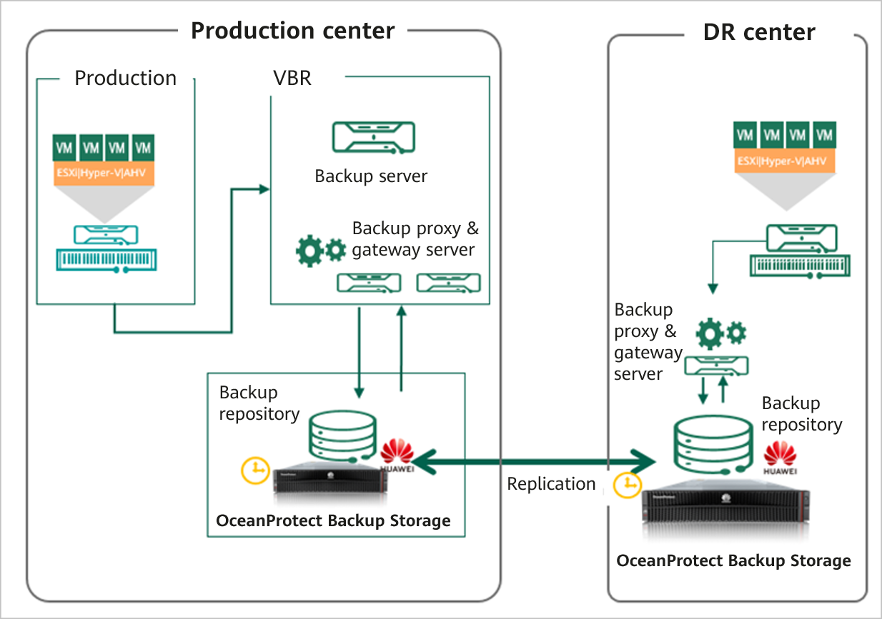
This solution uses the Veeam Backup & Replication 12 backup software to back up VMs to the OceanProtect Backup Storage. By establishing replication links between the local and remote ends, you can use the remote replication feature to replicate copies to the remote end.
Figure 2-2 Architecture of the VMware vSphere-based backup solution using the OceanProtect Backup Storage and Veeam Backup & Replication 12
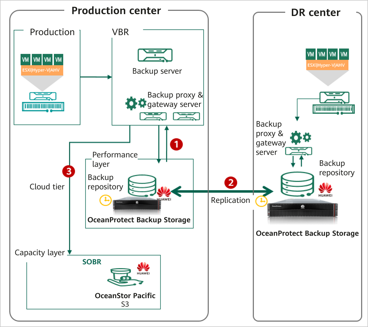
In the preceding figure, 1 indicates the backup and restoration process, 2 indicates the replication process, and 3 indicates the tiering process.
The functions of each component shown in Figure 2-2 are as follows:
- VMware vSphere: VMware virtualization environment for VM provisioning.
- Backup server: Veeam Backup & Replication is installed on the backup server. As the core component of the backup infrastructure, the backup server is responsible for performing all types of administrative activities, such as coordinating backup, replication, recovery verification, and restore tasks, controlling job scheduling and resource allocation, and setting and managing backup infrastructure components. In addition, the backup server also serves as the default backup proxy and the backup repository.
- Backup proxy: It operates as a data mover that transfers data between the source file and the backup repository. It also processes backup jobs and delivers backup and restoration traffic. For VMware backup, if the hot-add transmission mode is used, VMs must be used as backup proxies.
- Gateway server: It connects the production system and backend storage. Generally, the backup proxy also functions as the gateway server. In hot-add transmission mode, the backup proxy is a VM. Therefore, a physical host is used as the gateway server.
- Local OceanProtect Backup Storage: As a backup storage device, it creates file systems and mounts them to gateway servers as backup repositories using the Huawei DataTurbo protocol, to store Veeam backup copies.
- Remote OceanProtect Backup Storage: The local OceanProtect Backup Storage is connected to the remote OceanProtect Backup Storage through replication links. After a file system remote replication pair is created, copies can be replicated from the local end to the remote end.
2.2.2 Backup Solution Architecture
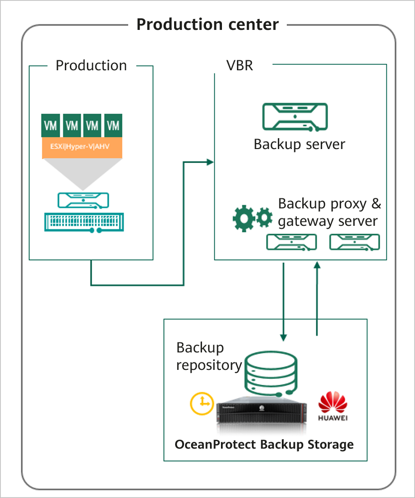
On the Veeam backup server, add the OceanProtect Backup Storage as the backup storage (backup repository).
The deduplication function of backup media is recommended because backup storage has excellent deduplication and compression performance. The active full and the synthetic full backup modes can be configured in Veeam backup policies. You can directly perform recovery based on backup jobs or use the instant recovery capability.
2.2.3 Replication Solution Architecture
Remote replication architecture and functions
- Use the OceanProtect backup storage for remote replication (HyperReplication). After the remote replication is created, use the backup software to import the data for recovery.
- Replication by using the backup software: Use the Backup Copy function of Veeam for remote replication of backup jobs. Snapshot-based replication is supported for some applications. Replication after deduplication and compression is supported.
Suggestion: Use the deduplicated replication and replication capability of the OceanProtect backup storage to save network bandwidth.
- In OceanProtect 1.5.0, copy-based restoration after remote replication can be performed without splitting the replication pair.
2.2.4 Tiering Solution Architecture
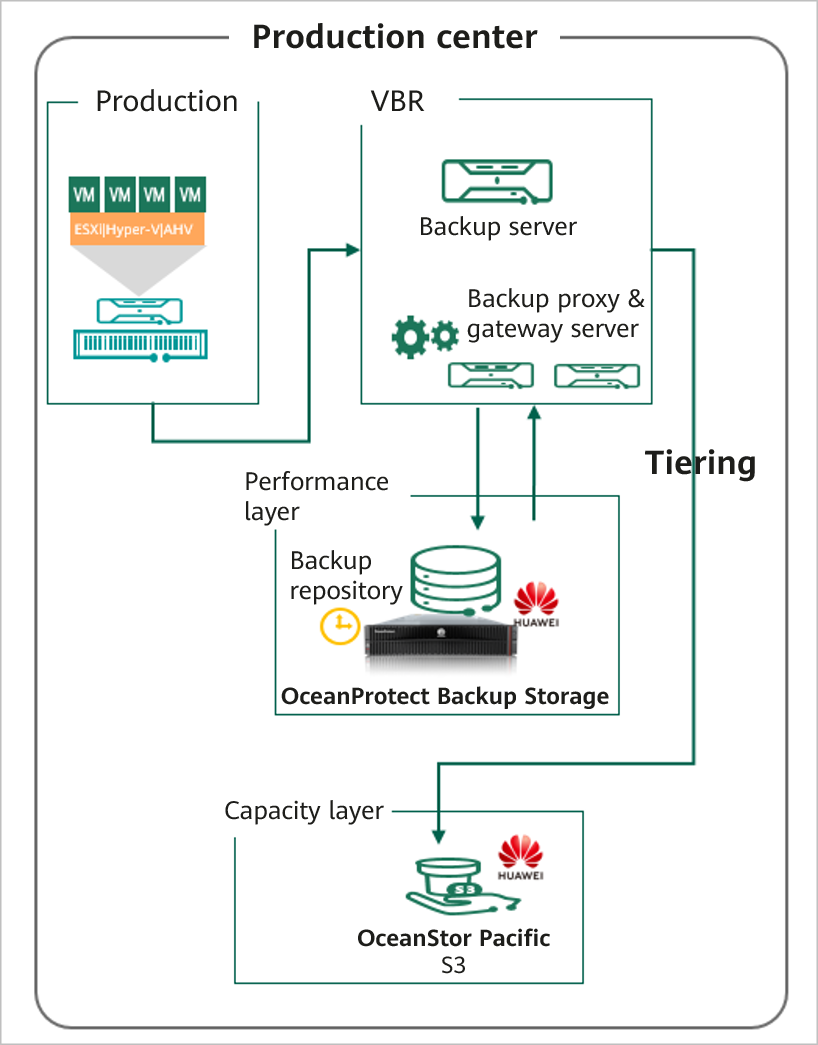
Description
The Veeam backup software supports multiple types of repositories, such as NAS and S3. Data can be stored in different types of repositories based on policies. The Cloud Tier function tiers copies that require long-term retention (LTR) to tier-2 media.
Application scenarios
- Different tiers correspond to different LTR policies of backup data. When a large amount of application data must be retained for a long time, customers usually use capacity storage as the level-2 backup device to reduce costs.
- The 3-2-1 Rule of the backup policy is used. The 3-2-1 Rule means there should be 3 copies of data on 2 different media with 1 copy being off site.
3 Planning and Configuration
3.1 Network Planning for Different OceanProtect Models
In OceanProtect 1.5.0, the customer can select OceanProtect X3000, X6000, X8000, and X9000 based on different backup capacity and performance requirements. The networking configuration principles of all models must comply with the principles described in 4.3 Configuration Planning for Veeam Interconnection.
3.2 Backup Capacity and Performance Planning
Backup capacity calculation
Generally, the capacity of OceanProtect X8000 is planned based on the customer’s backup data capacity and retention period.
Before planning and designing a backup solution, survey the customer’s production system and plan the backup system according to the following procedure.
- Configure a backup policy.
Survey the service systems to be backed up, and formulate a proper backup policy for each service system based on service requirements. For example, the frequency of full and incremental backups can be once every week and once every day respectively, and the backup data can be retained for one month. Table 3-1 lists typical backup policies.
Table 3-1 Typical backup policies
No. | Backup Object | Incremental Backup Frequency | Incremental Backup Copy Retention Period (Days) | Number of Incremental Backup Copies | Full Backup Frequency | Full Backup Copy Retention Period (Days) | Number of Full Backup Copies |
|---|---|---|---|---|---|---|---|
1 | VM | Every day | 90 | 87 | Every month | 90 | 4 |
2 | File | Every day | 90 | 77 | Every week | 90 | 14 |
3 | Every day | 365 | 353 | Every month | 365 | 13 | |
4 | Database | Every day | 90 | 77 | Every week | 90 | 14 |
2. Calculate backup capacity.
Survey the production capacity of each service system to be backed up and the data change rate (such as daily and annual change rates). Then, send the above survey information to Huawei technical support engineers to obtain the deduplication ratio and post-deduplication capacity. Table 3-2 shows typical examples of calculating the backup capacity.
Table 3-2 Backup capacity calculation
No. | Site | Backup Object | Initial Capacity (GB) | Capacity Growth Rate | Three-Year Capacity (GB) Before Deduplication | Data Deduplication Ratio | Three-Year Capacity (GB) After Deduplication |
|---|---|---|---|---|---|---|---|
1 | Data center | VM | 5000 | 1% per month | 32177 | 5:1 | 6435 |
2 | File | 2500 | 2% per month | 81206 | 5:1 | 16241 | |
3 | 1000 | 2% per month | 33199 | 8:1 | 4150 | ||
4 | Database | 5000 | 1% per month | 112042 | 3:1 | 37347 | |
5 | Total | 13500 | 258624 | 64175 | |||
6 | Remote site 1 | VM | 2500 | 1% per month | 16089 | 5:1 | 3218 |
7 | File | 1250 | 2% per month | 40603 | 5:1 | 8121 | |
8 | Total | 3750 | 56692 | 11339 | |||
9 | Remote site 2 | VM | 5000 | 1% per month | 32177 | 5:1 | 6435 |
10 | File | 3000 | 2% per month | 97447 | 5:1 | 19489 | |
11 | Total | 8000 | 129624 | 25924 | |||
12 | Total (all sites) | 25250 | 444940 | 101438 | |||
3. Calculate backup performance and bandwidth.
You are advised to perform the first full backup after the backup system is delivered for the first time. You need to plan a backup window for the first full backup. A daily backup window needs to be planned for periodic backup or incremental backup based on the backup policy required by the customer. Generally, it is recommended that the periodic full backup of each application system be performed in off-peak hours. In a period, the full and incremental backup jobs of each application system should be executed based on the backup policies. Table 3-3 shows typical examples of calculating backup performance and bandwidth.
Table 3-3 Examples for calculating backup performance and bandwidth
No. | Site | Backup Object | Daily Full Backup Volume After Three Years (GB) | Backup Time Window (Hours) | Backup Bandwidth (MB/s) |
|---|---|---|---|---|---|
1 | Data center | VM | 7154 | 4 | 509 |
2 | File | 5100 | 2 | 725 | |
3 | 2040 | 1 | 580 | ||
4 | Database | 7154 | 5 | 407 | |
5 | Remote site 1 | VM | 3577 | 2 | 509 |
6 | File | 2550 | 2 | 363 | |
7 | Remote site 2 | VM | 7154 | 4 | 509 |
8 | File | 6120 | 3 | 580 |
4. Determine the number of media servers based on the software recommendation. The following is for reference only.
In an actual project, select a proper type and number of media servers based on the front-end or back-end capacity. For Veeam 12:
- In principle, one VM disk to be backed up is one task, and two tasks consume one CPU of a backup proxy. For example, if a backup proxy is configured with eight CPU cores, 16 backup tasks can be executed at the same time, that is, backing up 16 VM disks.
- For a backup proxy, one CPU core requires 2 GB memory. For example, if eight CPU cores are configured, 16 GB memory is needed.
5. Create a replication policy.
If backup copy replication is required for DR, a replication policy must be created. You need to plan the execution window of the replication jobs. Table 3-4 lists typical replication policies.
Table 3-4 Replication policies
No. | Source Site | Target Site | Replication Type | Replication Trigger Type | Replication Time Window |
|---|---|---|---|---|---|
1 | Remote site 1 | Data center | Backup storage-based replication | Trigger by time, automatic copy | 7:00 to 11:00 |
2 | Remote site 2 | Data center | Backup storage-based replication | Trigger by time, automatic copy | 7:00 to 11:00 |
3 | Data center | Remote site 2 | Backup storage-based replication | Trigger by time, automatic copy | 11:00 to 21:00 |
6. Calculate replication performance and bandwidth.
Determine the replication time window based on customer requirements. Calculate replication performance requirements based on the volume of data to be replicated. Table 3-5 shows typical examples of calculating replication bandwidth.
Table 3-5 Typical examples of calculating replication bandwidth
No. | Source Site | Target Site | Daily Replication Data Volume (GB) | Replication Time Window (Hours) | Replication Bandwidth (MB/s) |
|---|---|---|---|---|---|
1 | Remote site 1 | Data center | 1225 | 2 | 174 |
2 | Remote site 2 | Data center | 2655 | 4 | 189 |
3 | Data center | Remote site 2 | 5090 | 9 | 161 |
Maximum daily replication data volume per site = ∑(Full backup data volume of all applications/Deduplication rate)

Generally, the backup performance of a backup system is planned based on the backup time window and backup capacity. In this best practice, the backup performance is 8 GB/s.
3.3 Planning and Configuration of Veeam Backup & Replication 12
Backup Server Planning
Backup server: The Veeam Backup & Replication software is installed on the backup server. It is the core component of the backup infrastructure, and manages all Veeam components. It can only be deployed on Windows. For details about compatible operating systems and other compatibility issues, see the Veeam official website.
Backup Proxy Planning
The hot-add transmission mode uses VMs in ESXi as backup proxies. For details about the planning suggestions, see Veeam official documentation.
- In principle, one VM disk to be backed up is one task, and two tasks consume one CPU of a backup proxy. For example, if a backup proxy is configured with eight CPU cores, 16 backup tasks can be executed at the same time, that is, backing up 16 VM disks.
- For a backup proxy, one CPU core requires 2 GB memory. For example, if eight CPU cores are configured, 16 GB memory is needed.
Gateway Server Planning
This solution adopts the SourceDedupe feature, using the DataTurbo protocol for interconnecting with OceanProtect X8000. The OceanStor DataTurbo software needs to be deployed on the gateway server.
- Server requirements: The backup capability of each gateway server is related to the server type. For details about the bandwidth capability of each server type, see the related Veeam documentation.
Plan the number of servers based on the required backup network bandwidth. For details about DataTurbo’s requirements on servers, see « Backup Server Requirements » in « Preparing the Environment, Software Package, and Tools » of OceanProtect Backup Storage 1.5.0 SourceDedupe User Guide.
- Operating system requirements: OceanStor DataTurbo, which supports both Linux and Windows operating systems, needs to be deployed on the gateway server. Therefore, the compatibility requirements must be met. For details, visit https://info.support.huawei.com/storage/comp/#/oceanprotect. In this best practice, the Windows operating system is used.
- NIC requirements: The gateway server is connected to both the production system and backup storage devices. Both the front-end and back-end NICs must meet the backup bandwidth requirements to avoid bottlenecks.
- Front-end network: It is used to connect to the production environment. To prevent the front-end network configuration from becoming a bottleneck, the capability of a single gateway server is evaluated as 2 GB/s, and the front-end network is prepared as 8 x 10GE in this solution. In actual tests, the front-end network can be adjusted based on the gateway server capability.
- Back-end network: This solution uses the SourceDedupe feature. Therefore, the back-end network of the gateway server does not need to have the same configuration as the front-end network. You are advised to connect each gateway server to controller A or B of OceanProtect X8000 through two 10GE optical fibers.
Backup Repository Planning
The file systems created by OceanProtect X8000 are mounted to gateway servers. This solution uses the DataTurbo protocol for mounting. You are advised to mount the file systems based on the following principles:
To ensure backup performance and reduction ratio, it is recommended that the number of file systems created on OceanProtect X8000 be the same as that of gateway servers, one file system be mounted to each gateway servers, and each mount point be created as an independent backup repository.
3.4 Planning and Configuration of OceanProtect X8000
Planning Storage Resources
- Disk type planning: Storage pools can be created using solid-state drives (SSDs) and hard disk drives (HDDs). Table 3-6 describes the disk type planning.
Table 3-6 Disk planning
Disk Planning | OceanProtect X8000 (all-flash) | OceanProtect X8000 (hybrid-flash) |
Disk Type | All disks in a storage pool are SSDs. | A storage pool consists of SSDs and HDDs. |
Disk Quantity |
|
|
- Storage capacity planning: The capacity of OceanProtect X8000 is planned based on the customer’s backup data capacity and retention period.
- Compression mode planning: The storage pool supports two compression modes: high reduction ratio (default) and high performance.
With regard to the compression ratio, High reduction ratio mode outperforms the high performance mode. If the customer has a tight backup window and requires high backup bandwidth, the high performance mode is recommended.
- Storage pool planning: A storage pool is a container that stores resources. It provides storage space for all application servers. For core services, RAID-TP is recommended. Table 3-7 describes the protection level policies of storage pools.
Table 3-7 Protection levels of storage pools
Protection Level | Number of Parity Bits | Redundancy and Data Recovery Capability | Maximum Number of Allowed Faulty Disks |
|---|---|---|---|
RAID 6 (default) | 2 | High. Parity data is distributed on different chunks. In each chunk group, the parity data occupies the space of two chunks. RAID 6 is able to tolerate simultaneous failures on two chunks. If three or more chunks fail, RAID 6 protection can no longer be provided. | 2 |
RAID-TP | 3 | High. Parity data is distributed on different chunks. In each chunk group, the parity data occupies the space of three chunks. RAID-TP is able to tolerate simultaneous failures on three chunks. If four or more chunks fail, RAID-TP protection can no longer be provided. | 3 |
File System Planning
- File system planning: Table 3-8 describes the key parameters that are used for file system planning.
Table 3-8 File system planning
Parameter | Description |
|---|---|
Capacity | The capacity of a file system is planned based on actual services. |
Quantity | Considering the performance and reduction ratio, it is recommended that the number of created file systems be the same as the number of gateway servers. |
Application type |
|
- File system sharing: OceanProtect X8000 provides CIFS, NFS, and DataTurbo shares. Windows SourceDedupe is planned in this solution. Therefore, select DataTurbo shares for file system sharing. For details about the operating system versions and backup software versions supported by the DataTurbo client, see the compatibility query website.

Compatibility query website: https://info.support.huawei.com/storage/comp/#/oceanprotect
Network Planning
- Planning physical ports
- Quantity planning: After SourceDedupe is activated, the required physical bandwidth can be planned based on the number of backup hosts. 2 x 10GE for each backup host can meet the bandwidth requirements. For example, if there are four backup hosts, eight physical ports are needed for the back-end OceanProtect X8000.
- Configuration planning: OceanProtect X8000 is a dual-controller device. To ensure reliability, the planned NICs must be evenly distributed to controllers A and B.
- Planning logical ports
- Quantity planning: Logical ports are created for running NAS services. You are advised to configure at least one logical port for each physical port.
- Configuration and planning: OceanProtect X8000 has two controllers: controller A and controller B. It is recommended that two backup hosts be connected to the logical ports on controllers A and B of the OceanProtect X8000 separately through two 10GE optical fibers, and other backup hosts be connected in similar way.

To achieve a good deduplication effect, you are advised to disable the deduplication and compression functions of backup software and disable the compression and encryption functions of applications to be backed up. For example, disable compression and encryption of Oracle RMAN.
4 Configuration Example
This section describes a configuration example of backing up VMware virtualization data using OceanProtect X8000 and Veeam Backup & Replication 12.
4.1 Networking Diagram
4.1.1 VMware Hot-Add Transmission Networking (Four Gateway Servers)
Figure 4-1 shows the backup verification networking of OceanProtect X8000.
Figure 4-1 Networking diagram for backing up VMs using OceanProtect X8000 and Veeam (VMware transmission mode: hot-add)
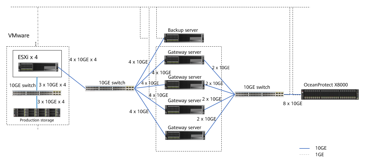

The networking diagram shown in Figure 4-1 is for reference only. For details about the cable connections between the controller enclosures and application servers, between the controller enclosures and disk enclosures, and between controller enclosures, see « Cabinet Layout and Connection Planning » in the OceanProtect X6000, X8000 1.x Installation Guide.
Networking description:
- VMware vSphere: In this best practice, VMs are deployed through four ESXi physical hosts.
- Three 10GE distributed ports (working in active/standby mode) are configured for each ESXi physical host through vCenter.
- Four ESXi hosts are connected to OceanStor Dorado 8000 as the production storage through three 10GE iSCSI links. Four VMs are planned for each datastore. A total of 28 VMs are deployed, and each VM contains six disks, including one system disk and five data disks. A total of about 500 GB or 600 GB data is preset in the data disks.
- Backup server: connects to a 10GE switch through two 10GE optical fibers, runs the Windows operating system, and manages backup components and backup tasks. In addition, Veeam Console is deployed on it.
- Backup proxy: works in hot-add transmission mode. Each ESXi host uses four VMs (Linux) as backup proxies. There are 16 backup proxies in total. In addition, a 32-core CPU and 64 GB memory are configured for each backup proxy.
- Gateway server: Four gateway servers are connected to ESXi hosts and OceanProtect X8000 through 10GE switches.
- Front-end network: Each gateway server uses four 10GE optical fibers to connect to ESXi hosts through 10GE switches. 4 x 10GE bonding (mode 0) is configured for each gateway server (Linux host), and Eth-Trunk (mode manual) is configured on the switches.
- Back-end network: Each gateway server uses two 10GE optical fibers to connect to OceanProtect X8000 through 10GE switches. Each gateway server uses two 10GE optical fibers to connect to two ports on controller A or B of OceanProtect X8000.
- OceanProtect X8000: OceanProtect X8000 connects to four gateway servers through a 10GE switch. Controllers A and B of OceanProtect X8000 are separately connected to the 10GE switches through four 10GE optical fibers.
4.2 Hardware and Software Configuration
4.2.1 Hardware Configuration
Table 4-1 Hardware requirements
Name | Description | Quantity | Function |
|---|---|---|---|
ESXi server | x86 server
| 8 | Used to create VMs as file system hosts. |
Gateway Server | x86 server
| 4 | Used to install the Linux operating system and OceanProtect DataTurbo software to schedule backup tasks and transmit backup data. |
Backup server | VM
| 1 | Used to install the Windows operating system and functions as the backup server to manage backup jobs and backup copies. |
Production storage | OceanStor Dorado 6000, dual controllers, 25 x 7.68 TB SAS SSDs, 3 x 4-port 16 Gbit/s Fibre Channel SmartIO cards | 1 | Used as production storage of the ESXi server. |
Production storage | OceanStor Dorado 8000, dual controllers, 26 x 7.68 TB SSDs, 5 x 4-port 10 Gbit/s SmartIO cards | 1 | Used as production storage of the ESXi server. |
10GE switch | Huawei CE6850 | 3 | 10GE switch on the backup service plane. |
4.2.2 OceanProtect X8000 (All-Flash) Configuration
Table 4-2 OceanProtect X8000 (all-flash) configuration
Name | Description | Quantity |
|---|---|---|
OceanProtect engine | Huawei OceanProtect X8000 with dual controllers | 1 |
10GE front-end interface module | Four 10 Gbit/s SmartIO interface modules | 4 |
SAS SSD | Huawei 7.68 TB SAS SSDs | 25 |
4.2.3 Test Software and Tools
Table 4-3 Software description
Software Name | Description |
|---|---|
OceanProtect DataTurbo 1.2.0 | The SourceDedupe client, which is deployed on the backup server to perform source deduplication and compression on backup data, reducing the amount of physical data transmitted from the backup server to the storage and improving the overall bandwidth capability of backup services. |
Veeam Backup & Replication 12 | Veeam backup and restoration software |
ESXi 7.0 | Enterprise-level hypervisor developed by VMware, which is used to provide hardware virtualization services. |
Windows Server 2019 | Operating system equipped with Windows Gateway Server |
Vdbench 5.04.06 | Third-party tool for generating test data |
4.3 Configuration Planning for Veeam Interconnection
4.3.1 VM Backup Planning Using OceanProtect X8000 (Backup Repository)
Four gateway servers are used to back up VMs through backup repositories of Veeam in this solution.
- Storage pool on OceanProtect X8000: Create a storage pool with 25 x 7.68 TB SAS SSDs, and set the RAID policy to RAID 6.
- File systems on OceanProtect X8000: To ensure backup performance and deduplication and compression effects, plan four file systems (two file systems for each controller, and 100 TB for each file system). In addition, if the same data is backed up for multiple times, ensure that it is backed up to the same file system each time.
- Logical ports on OceanProtect X8000: OceanProtect X8000 is connected to the four front-end gateway servers through 8 x 10GE physical links. Each physical port is configured with one logical port.
- Connections established using OceanStor DataTurbo: This solution uses the SourceDedupe feature. The file systems created on OceanProtect X8000 need to use the DataTurbo protocol to connect to the gateway servers. After the OceanStor DataTurbo software is installed on the gateway servers, it is recommended that each gateway server be connected to the two ports on controller A or B of OceanProtect X8000 through two 10GE optical fibers before mounting the file systems.
- Veeam backup repository planning: A total of four Veeam backup repositories are configured on Veeam.
- Mounting principles: The four file systems are separately mounted to different gateway servers. One file system is mounted to one gateway server. Two file systems separately are created for controllers A and B.
- Veeam backup repository: Each mount point is configured as an independent backup repository.
- Veeam job configuration: All VMs to be backed up are evenly distributed to four backup jobs and data is backed up to the four different backup repositories.
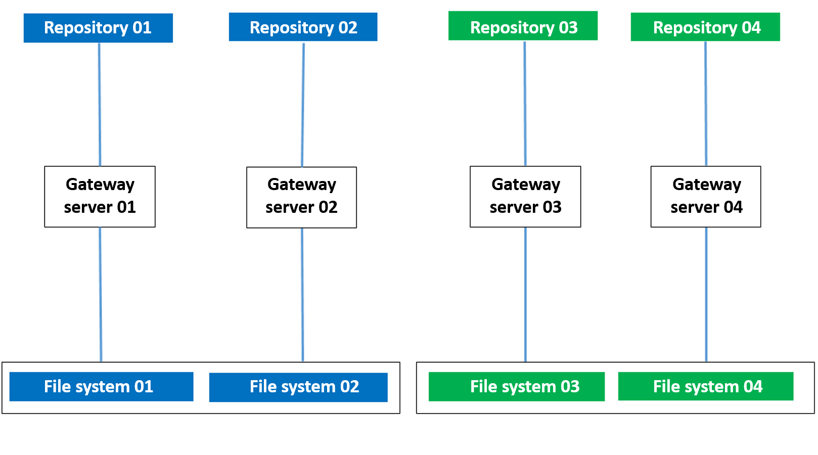
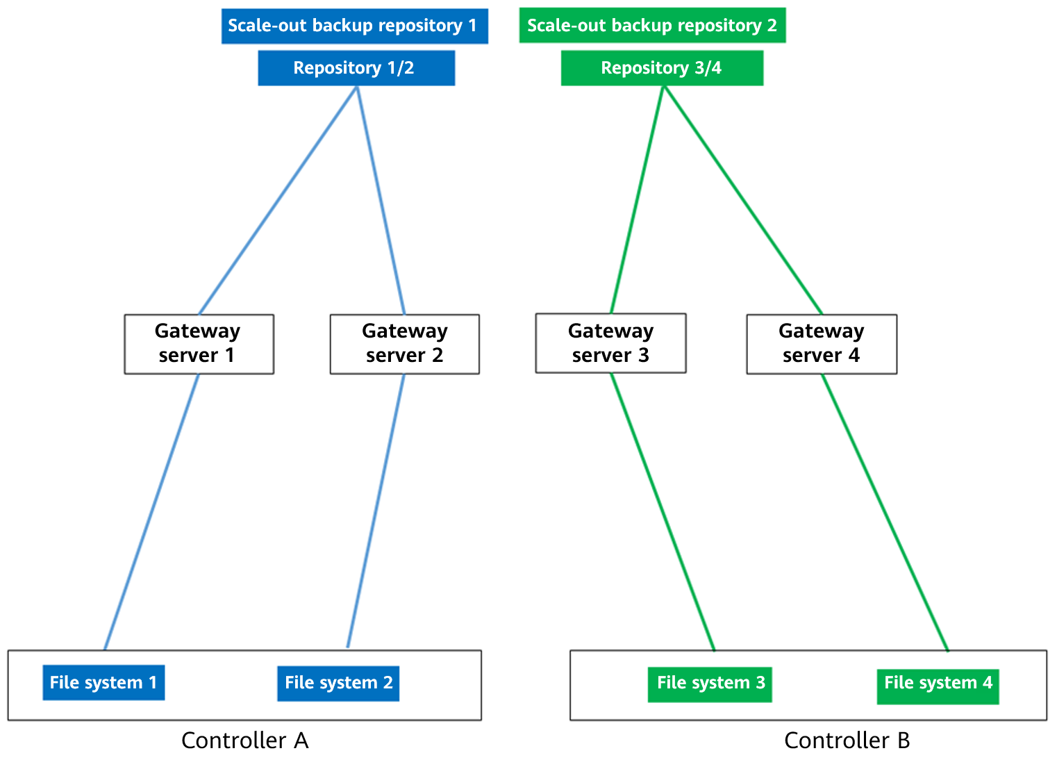
4.3.2 VM Backup Planning Using OceanProtect X8000 (Scale-Out Backup Repository)
Four gateway servers are used to back up VMs through scale-out backup repositories of Veeam in this solution.
- Storage pool on OceanProtect X8000: Create a storage pool with 25 x 7.684 TB SSDs, and set the RAID policy to RAID 6.
- File systems on OceanProtect X8000: Plan four file systems (two file systems for each controller, and 100 TB for each file system). In addition, if the same data is backed up for multiple times, ensure that it is backed up to the same file system each time so that data can be deduplicated and compressed.
- Logical ports on OceanProtect X8000: OceanProtect X8000 is connected to the four front-end gateway servers through 8 x 10GE physical links. Each physical port is configured with one logical port.
- Connections established using OceanStor DataTurbo: This solution uses the SourceDedupe feature. The file systems created on OceanProtect X8000 need to use the DataTurbo protocol to connect to the gateway servers. After the OceanStor DataTurbo software is installed on the gateway servers, it is recommended that each gateway server be connected to the two ports on controller A or B of OceanProtect X8000 through two 10GE optical fibers before mounting the file systems.
- Veeam backup repository planning: Create a Veeam backup repository for each file system on Veeam (four backup repositories in total). Create two scale-out backup repositories, and add the backup repositories of the two file systems belonging to the same controller to each scale-out backup repository.
- Mounting principles: The four file systems are separately mounted to different gateway servers. One file system is mounted to one gateway server. Two file systems separately are created for controllers A and B.
- Veeam backup repository: Each mount point is configured as an independent backup repository. The backup repositories of two file systems on the same controller are configured as a scale-out backup repository.
- Veeam job configuration: All VMs to be backed up are evenly distributed to four backup jobs and data is backed up to four different backup repositories through scale-out backup repositories.

Backup principle: Periodic backup copy data of the same type of applications is written to the same deduplication domain.
Networking principles:
- Scenario involving Veeam scale-out backup repositories: It is recommended that one scale-out backup repository be planned for one type of applications. One scale-out backup repository corresponds to file systems on the same controller of OceanProtect, and one repository is configured for one each file system. In the scale-out backup repository, one repository corresponds to one backup media server.
- Scenario involving only repositories: It is recommended that one repository be planned for a type of applications. The mapping relationship between repositories and file systems or backup media servers is one-to-one.
- To use OceanProtect X9000 while maximizing the performance of HDDs, 16 file systems are required.
- Plan the actual number of file systems based on customer services. (To ensure performance and deduplication and compression ratio, you are advised to configure at least one file system for each controller.)
4.4 Veeam Resource Scheduling Parameters
Table 4-4 Veeam resource scheduling parameters
Veeam Parameter or Option | Module | Description |
|---|---|---|
Maximum number of concurrent tasks on a backup proxy | Backup proxy | The maximum number of concurrent tasks on the backup proxy depends on the number of available CPU cores on the backup proxy. You are advised to use the following rule on Veeam 12 to define the job upper limit: two jobs per CPU core. For example, if a backup agent has four CPU cores, you are advised to set the maximum number of concurrent jobs on the backup agent to 8. For details, see the concurrent job limitation on the Veeam official website. |
Maximum number of concurrent tasks on a backup repository | Repository | 1. You can enable the Limit maximum concurrent tasks to <N> option on the backup repository to limit the number of concurrent jobs. N indicates the expected maximum number of concurrent jobs. 2. In the current version, you are advised to deselect the Limit maximum concurrent tasks to <N> option. |
Limitation of read and write data rates for backup repositories | Repository | 1. You can enable the Limit read and write data rate to <N> MB/s option in backup repository settings to control the data read/write speed. N indicates the expected data read/write speed. 2. In the current version, you are advised to deselect the Limit read and write data rate to <N> MB/s option. |
Specifying preferred networks | Global network traffic rules | You can choose networks over which Veeam Backup & Replication must transport data when you perform data protection and disaster recovery tasks. For details, see the Veeam official website. |
Compression | Job | Deselect the Enable inline data deduplication(recommended) check box to disable the compression feature of Veeam. |
Deduplication | Job | Set Compression level to None to disable the deduplication feature of Veeam. |
Backing Up Files by Host | Global network traffic rules | With the Use per-machine backup files option enabled, Veeam Backup & Replication writes VM data to the backup repository in several streams, which improves the backup job performance. |
Backup file storage policies | Scale-out backup repository |
|
Synthetic full backup policies | Repository | If Linux source deduplication is used, select Use fast cloning on XFS volumes. If Windows source deduplication is used, deselect this option because Fast Clone is automatically enabled for the system. |
4.5 VMware Backup and Recovery Configuration
4.5.1 Configuration Process
Figure 4-2 Configuration process
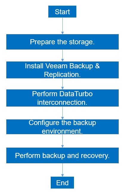
4.5.2 Preparing the Storage
In this solution, four file systems and a DataTurbo share are created on OceanProtect X8000. Each file system is mounted to Veeam through two links as a backup repository. The configuration procedure is as follows: create a storage pool, create logical ports, create a DataTurbo user, create file systems, and create file system shares.
4.5.2.1 Creating a Storage Pool
Step 1 To create a storage pool on OceanProtect X8000, select 25 disks and set the RAID policy to RAID 6.
The following figure shows an example of configuring a storage pool:
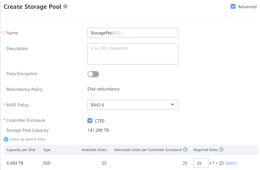
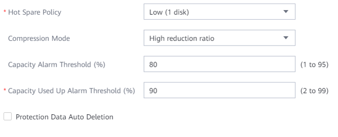
Step 2 Click Advanced to set Compression mode. You can set Compression mode to High reduction ratio (default value) or High performance as required.
—-End
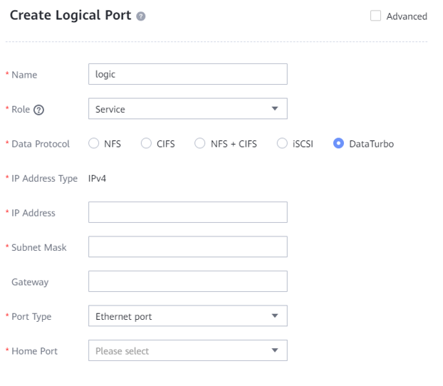
4.5.2.2 Creating Logical Ports
In this solution, OceanProtect X8000 has eight physical ports, each of which is configured with one logical port. Therefore, you need to create a total of eight logical ports and set DataTurbo as the data protocol.
The following figure shows a configuration example.
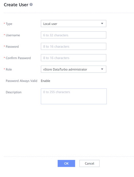
4.5.2.3 Creating a DataTurbo User
To create a DataTurbo share, you need to create a vStore DataTurbo administrator in advance. You need to use the administrator to create and connect to storage objects during mounting on a proxy host.
Go to Services > vStore Service > vStores, select the vStore in use, select User Management, click Create, and the system will display the Create User page. On the Create User page, set Type to Local user, enter the name and password, and set Role to vStore DataTurbo administrator. The following figure shows a configuration example.
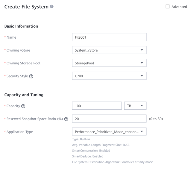
4.5.2.4 Creating File Systems
Step 1 Create four file systems and select the created storage pool. The capacity of each file system is 100 TB.
Step 2 If the application type is set to Reduction_Prioritized_Mode_enhanced, Compression mode of the storage pool is set to High reduction ratio to save storage resources. If the application type is set to Performance_Prioritized_Mode_enhanced, the compression mode of the storage pool is set to High performance.
Step 3 Set Security Style to NTFS if Windows source deduplication is used and to UNIX if Linux source deduplication is used. The following figure shows a configuration example.
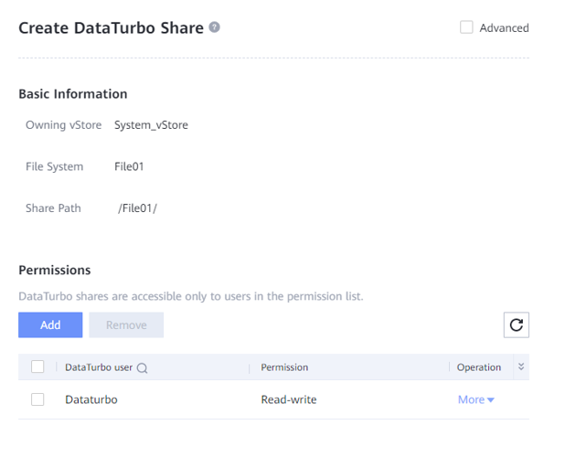
4.5.2.5 Creating File System Shares
Create a DataTurbo share for each file system and select the configured DataTurbo user.
4.5.3 Installing Veeam Backup & Replication 12
In the Veeam environment, you only need to manually install the Veeam Backup & Replication 12 software on the Windows host where the backup server is located. The software is automatically installed on other components during the Veeam configuration.
For details about how to install Veeam Backup & Replication, see the official documentation. This document describes how to configure each component on the Veeam Backup & Replication 12 console.
4.5.4 DataTurbo Interconnection
This solution uses the SourceDedupe feature, which requires the DataTurbo protocol for interconnecting with the gateway servers. DataTurbo shares are created on OceanProtect X8000. To mount the corresponding file systems to the backup hosts using the DataTurbo protocol, you need to install the OceanStor DataTurbo software and configure related parameters on the gateway servers.
4.5.4.1 Installation and Deployment
OceanStor DataTurbo must be installed on all gateway servers. For details about how to install OceanStor DataTurbo, see « Installation, Upgrade, and Uninstallation » in the OceanProtect Backup Storage 1.5.0 SourceDedupe User Guide. Considering the performance and reliability of Veeam and Windows source deduplication on the gateway server, you are advised to select the low level during the installation.
4.5.4.2 Parameter Configuration
The DataTurbo configuration consists of two parts: establishing connections and mounting file systems.
- Establishing connections: The two ports of each gateway server are separately connected to the two logical ports on controller A or B of OceanProtect X8000. That is, each backup host is connected to the back-end storage through two 10GE optical links.
- Mounting file systems: Create four file systems on OceanProtect X8000, and separately mount the file systems to the four front-end backup hosts. For details, see 4.3 Configuration Planning for Veeam Interconnection.
Establishing Connections
Step 1 Run the dataturbo create storage_object storage_name=name ip_list=IP command (name indicates the defined storage name, and IP indicates the IP address of the logical port created on OceanProtect X8000) to connect OceanStor DataTurbo and OceanProtect X8000. Enter the user name and password of the created DataTurbo user as prompted.
In the following example, the storage device name is storage1 and the logical port IP address is 10.10.10.10.
C:\Users\Administrator>dataturbo create storage_object storage_name=storage1 ip_list=10.10.10.10
Please input username:
dataturbo_user
Please input password:
**********
Create storage object successfully.
Step 2 Run the dataturbo show storage_object command to check whether the connection is established successfully.
If the following information is displayed and Status is Normal, the connection is established successfully.
C:\Users\Administrator>dataturbo show storage_object
Storage Name: storage1
User : dataturbo_user
Ips : 10.10.10.10
IpPair :
ID Local Address Remote Address Status
—————————————————————
1 10.10.10.101 10.10.10.10 Normal
Step 3 After the connection is established, go to Services > DataTurbo Clients on DeviceManager of the backup storage to view the backup server information.
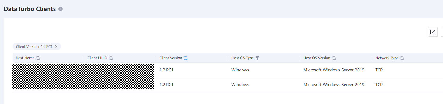
—-End
Mounting File Systems
Step 1 Run the dataturbo mount storage_object storage_name=name filesystem_name=/fsname mount_dir=H: enable_user_security=false command to mount a file system created on the Backup Storage to a specified mount point.
name indicates the storage name defined in Establishing Connections. fsname indicates the name of the DataTurbo share path created in 4.5.2.5 Creating File System Shares.
In the following example, the storage name is storage1, the file system name is testfile, and the mount point is H:.
C:\Users\Administrator>dataturbo mount storage_object storage_name=storage1 filesystem_name=/testfile mount_dir=H: enable_user_security=false
Command executed successfully.
Step 2 Run the dataturbo show mount_dir command to check whether the mounting is successful.
C:\Users\Administrator>dataturbo show mount_dir
StorageName FilesystemName MountPoint EnableUserSecurity
————————————————————————————————–
storage1 /testfile H: false
Step 3 Configure the mount point to be persistent. To ensure that the configured mount information is not lost after the backup server is restarted, configure the mount information in the \oceanstor\dataturbo\conf\dpc_mount_tab file in the installation path in the specified format. The following provides a configuration example, where file system /testfile, mount point H:, and the ACL configuration are separated by spaces.
# ———————————-Description———————————— #
# File system written in this config file will be automatically mounted to the
# mount directory when the operating system starts up. Remove the mount information
# from this file if you do not need it to be mounted automatically at the start.
#
# Config Format:
# filesystem_name mount_dir mount_option
# Example:
# /exampleFileSystem « E: » enable_user_security=false
# ——————————————————————————— #
/testfile « H: » enable_user_security=false
Step 4 (Optional) Enable the FileRangeClone function if the Fast Clone feature is required during synthetic full backup. For details, see « Configuring FileRangeClone » in the OceanProtect Backup Storage 1.5.0 SourceDedupe User Guide.
4.5.5 Configuring the Backup Environment (Backup Repository)
This section describes the configuration planning for the interconnection between OceanProtect X8000 and Veeam Backup & Replication 12.
4.5.5.1 Adding a Windows Server
All Veeam-related servers must be configured on Veeam.
Adding a Windows Server
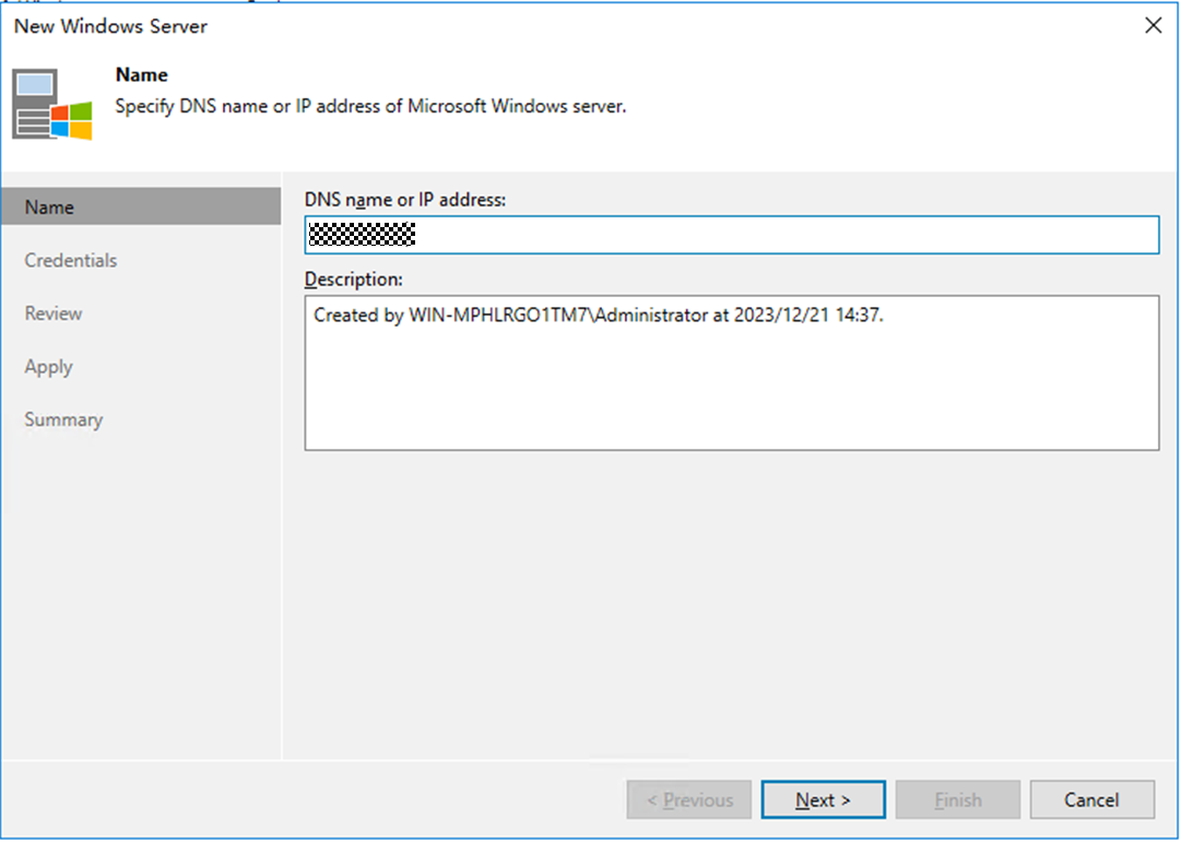
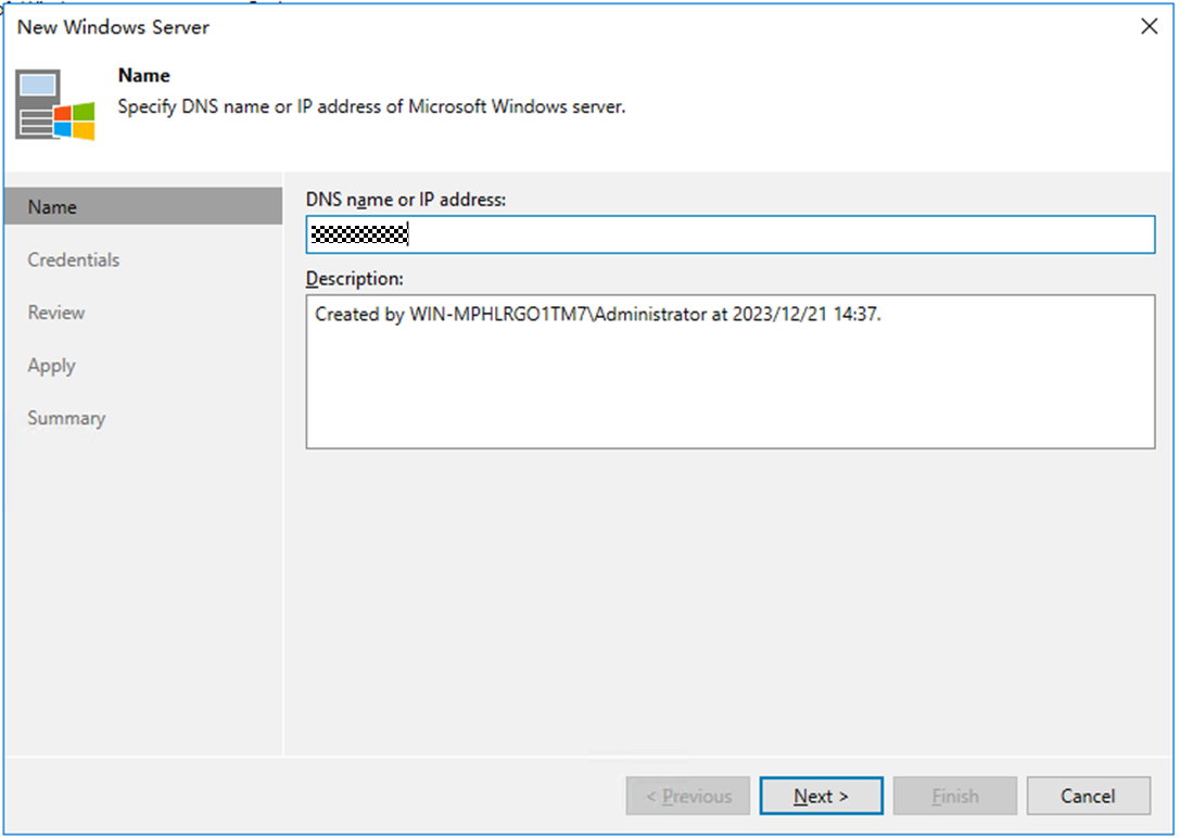
Step 1 On the Backup Infrastructure window, right-click Microsoft Windows under Managed Servers and choose Add server from the shortcut menu. Enter the IP address of the Windows host to be added, and click Next.
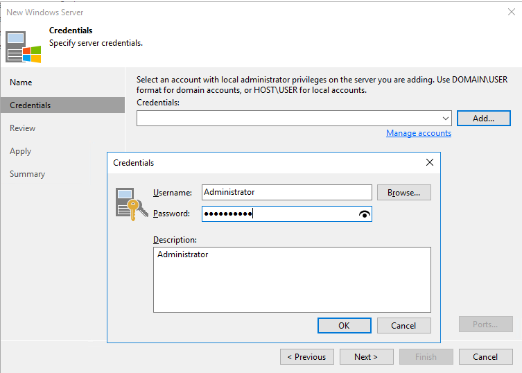
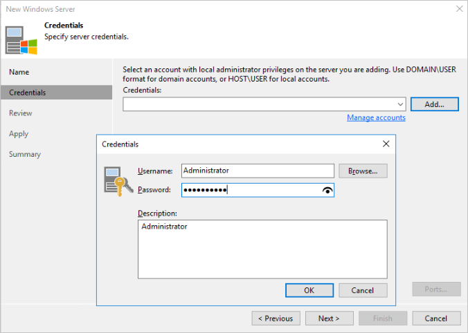
Step 2 Enter the username and password and click Next.
Step 3 Perform operations as prompted.
—-End
4.5.5.2 Configuring Backup Proxies
In this best practice, the hot-add transmission mode is used to back up VMs. Four VMs with 32-core CPUs on each ESXi host are used as backup proxies.
The backup proxy configuration in this section is for reference only. For details, see the official documentation.
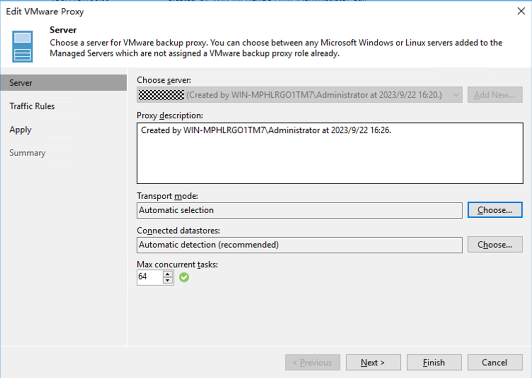
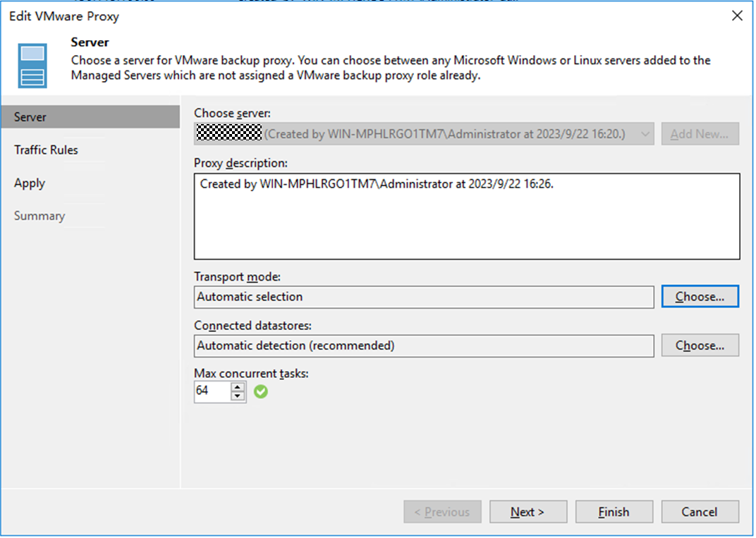
Step 1 Choose Backup Infrastructure, right-click Backup Proxies, and choose Add VMware backup proxy from the shortcut menu. On the page that is displayed, select the VM to be added.
- Transport mode: If this parameter is set to Automatic selection, Veeam automatically selects Direct storage access, Virtual appliance (Hot-Add), and Network (NBD) in sequence. In this solution, Direct storage access is not configured. Therefore, if this parameter is set to Automatic selection, Hot-Add is automatically selected.
- Max concurrent tasks: indicates the maximum number of tasks that can be concurrently processed by a backup proxy. If the number of concurrent tasks reaches this value, the backup proxy does not start a new task until the current tasks are completed. Veeam Backup & Replication creates a task for each VM disk. The recommended number of concurrent tasks is automatically calculated based on the available resources. Backup proxies with multi-core CPUs can process more concurrent tasks. For example, you are advised to set the value to 8 for a 4-core CPU and 16 for an 8-core CPU. In this solution, set this parameter based on the number of CPU cores of the proxy. In this example, set this parameter to 64, and click Next.
Step 2 Retain the default settings in the subsequent steps and perform operations as prompted.
—-End
4.5.5.3 Configuring Backup Repositories
In this solution, use four file systems created on OceanProtect X8000 to configure four backup repositories.
The procedure for creating a backup repository in this section is for reference only. For details, see the official documentation.
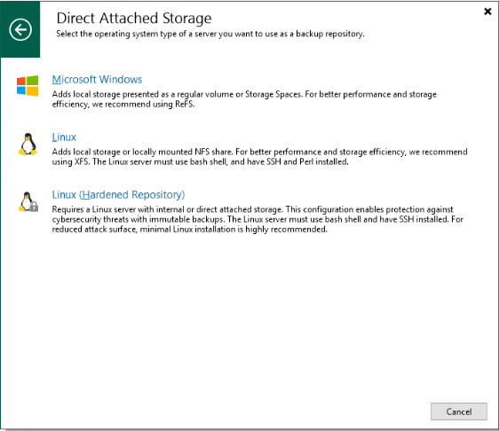
Step 1 Choose Backup Infrastructure, click Backup Repository, and right-click Add backup repository.On the page that is displayed, select Direct attached storage and Microsoft Windows in sequence.

Step 2 On the Name page, enter a name for the repository.
Step 3 On the Server tab page, select the gateway server in the networking diagram.
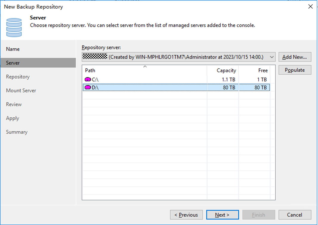
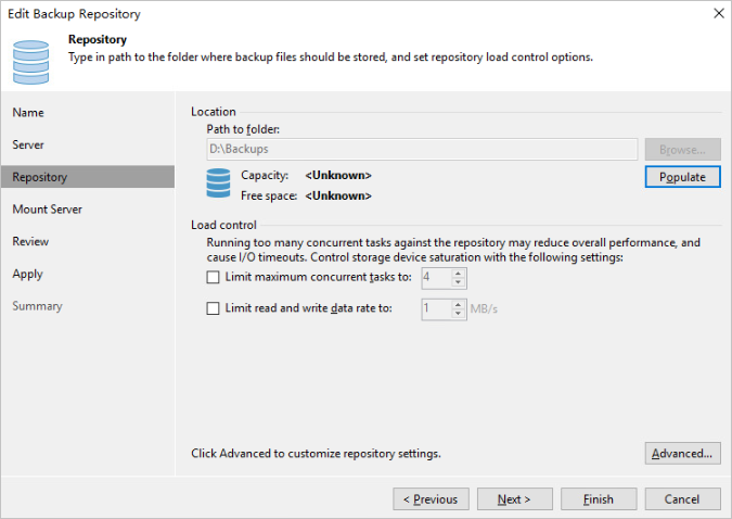
Step 4 Perform the following operations on the Repository tab page:
- Select the mount directory of the file system for Path to folder .
- Change the maximum number of concurrent tasks based on the number of tasks carried by each backup repository. Set this parameter to a value greater than the number of tasks. In this solution, the maximum performance is tested as a target. Therefore, the maximum number of concurrent tasks is not limited. In an actual backup system, you can set this parameter based on the system load requirements. Click Next.
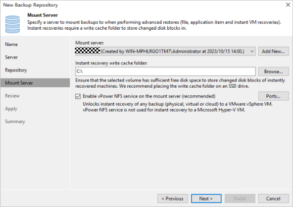
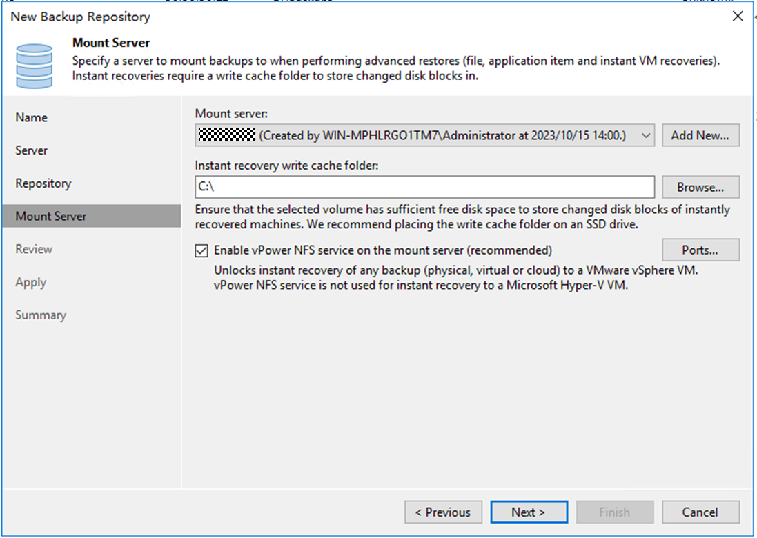
Step 5 On the displayed Mount Server page, select the repository server to which the backup repository is mounted. Click Next.
- Mount server: This parameter is mainly used for instant recovery. Only the Windows operating system is supported. In this solution, the repository server is selected by default to serve as the mount server.
- Instant recovery write cache folder: This parameter specifies a cache location for instant recovery. The reserved space must be 200 MB greater than the memory of the VM to be restored to ensure successful instant recovery. For example, if 10 VMs are to be restored and each VM has 16 GB memory, ensure that the available space of Instant recovery write cache folder is greater than 160.2 GB.
Step 6 Click Apply and perform operations as prompted.
—-End
4.5.5.4 Configuring VMware vSphere
Step 1 On the Backup Infrastructure page, right-click VMware vSphere and choose Add server from the shortcut menu. Enter the IP address in Name and click Next.

Step 2 On the Credentials page, add the username and password and click Apply. Perform subsequent operations as prompted.
—-End
4.5.5.5 Configuring VM Backup Jobs
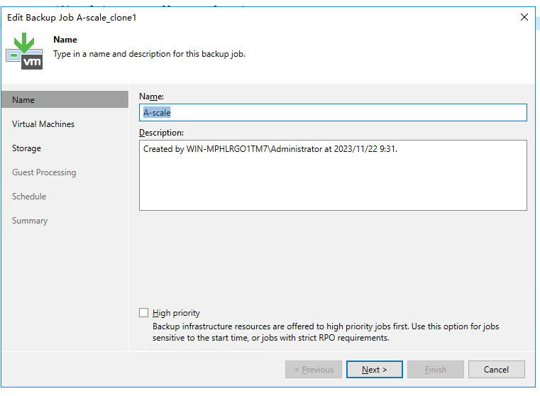
Step 1 On the Home page, choose Jobs > Backup. From the drop-down list, click Virtual machine. On the Name page that is displayed, specify Name and click Next.
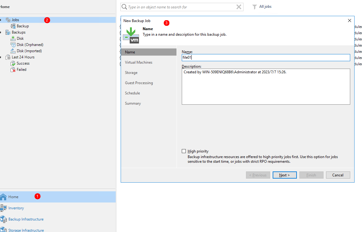
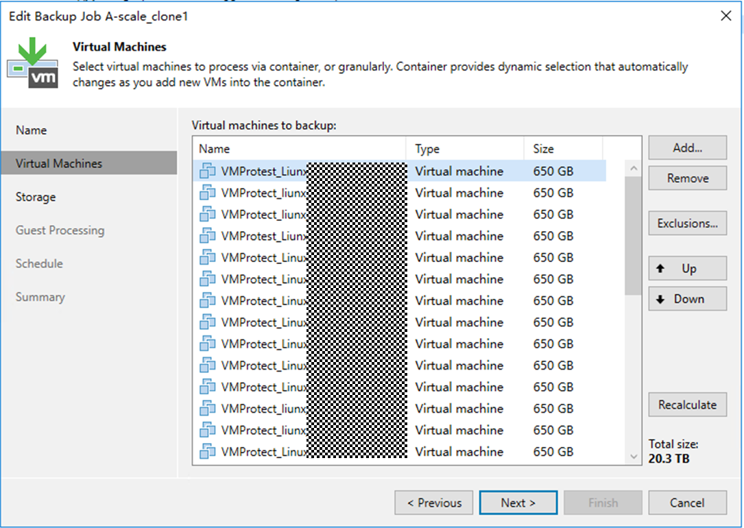
Step 2 Click Add to add the VM to be backed up and click Next.
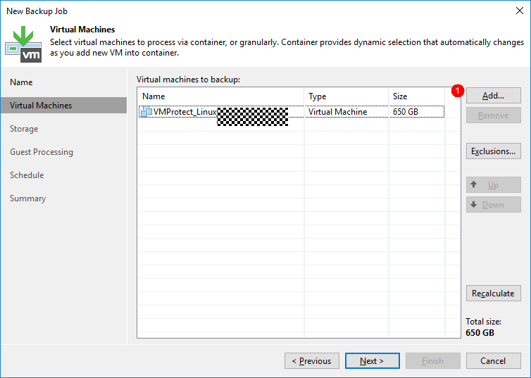
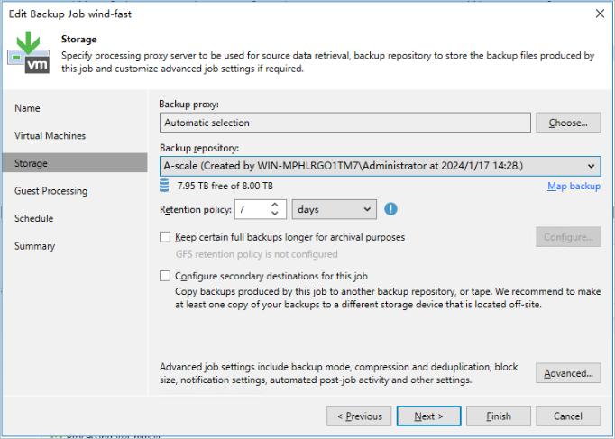
Step 3 On the Storage page, retain the default setting Automatic selection for Backup proxy and select the previously configured backup repository for Backup repository.
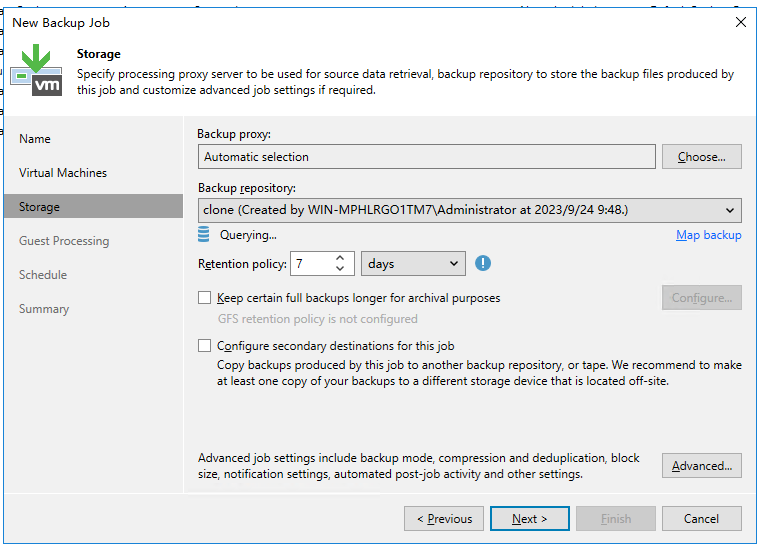
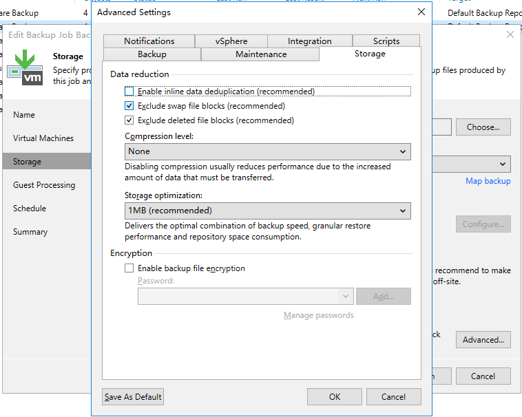
Step 4 Click Advanced. On the Storage tab page, deselect Enable inline data deduplication (recommend) to disable the deduplication function of the backup software. Set Compression level to None to disable the compression function of the backup software. Click OK. Perform subsequent operations as prompted.

—-End
4.5.6 Configuring the Backup Environment (Scale-Out Backup Repository)
This section describes the configuration planning for the interconnection between OceanProtect X8000 and Veeam Backup & Replication 12.
4.5.6.1 Adding a Windows Server
All Veeam-related servers must be configured on Veeam.
Adding a Windows Server
Step 1 On the Backup Infrastructure window, right-click Microsoft Windows under Managed Servers and choose Add server from the shortcut menu. Enter the IP address of the Windows host to be added, and click Next.
Step 2 Click Add. In the dialog box that is displayed, enter the username and password and click Next.
Step 3 Perform operations as prompted.
—-End
4.5.6.2 Configuring Backup Proxies
In this best practice, the hot-add transmission mode is used to back up VMs. Four VMs with 32-core CPUs on each ESXi host are used as backup proxies.
The backup proxy configuration in this section is for reference only. For details, see the official documentation.
Step 1 Choose Backup Infrastructure, right-click Backup Proxies, and choose Add VMware backup proxy from the shortcut menu. On the page that is displayed, select the VM to be added.
- Transport mode: If this parameter is set to Automatic selection, Veeam automatically selects Direct storage access, Virtual appliance (Hot-Add), and Network (NBD) in sequence. In this solution, Direct storage access is not configured. Therefore, if this parameter is set to Automatic selection, Hot-Add is automatically selected.
- Max concurrent tasks: indicates the maximum number of tasks that can be concurrently processed by a backup proxy. If the number of concurrent tasks reaches this value, the backup proxy does not start a new task until the current tasks are completed. Veeam Backup & Replication creates a task for each VM disk. The recommended number of concurrent tasks is automatically calculated based on the available resources. Backup proxies with multi-core CPUs can process more concurrent tasks. For example, you are advised to set the value to 8 for a 4-core CPU and 16 for an 8-core CPU. In this solution, set this parameter based on the number of CPU cores of the proxy. In this example, set this parameter to 64, and click Next.
Step 2 Retain the default settings in the subsequent steps and perform operations as prompted.
—-End
4.5.6.3 Configuring Backup Repositories
In this solution, use four file systems created on OceanProtect X8000 to configure four backup repositories.
The procedure for creating a backup repository in this section is for reference only. For details, see the official documentation.
Step 1 Choose Backup Infrastructure, click Backup Repository, and right-click Add backup repository.On the page that is displayed, select Direct attached storage and Microsoft Windows in sequence.
Step 2 On the Name page, enter a name for the repository.
Step 3 On the Server tab page, select the gateway server in the networking diagram.

Step 4 Perform the following operations on the Repository tab page:
- Select the mount directory of the file system for Path to folder .
- Change the maximum number of concurrent tasks based on the number of tasks carried by each backup repository. Set this parameter to a value greater than the number of tasks. In this solution, the maximum performance is tested as a target. Therefore, the maximum number of concurrent tasks is not limited. In an actual backup system, you can set this parameter based on the system load requirements. Click Next.

Step 5 On the displayed Mount Server page, select the repository server to which the backup repository is mounted. Click Next.
- Mount server: This parameter is mainly used for instant recovery. Only the Windows operating system is supported. In this solution, the repository server is selected as the mount server.
- Instant recovery write cache folder: This parameter specifies a cache location for instant recovery. The reserved space must be 200 MB greater than the memory of the VM to be restored to ensure successful instant recovery. For example, if 10 VMs are to be restored and each VM has 16 GB memory, ensure that the available space of Instant recovery write cache folder is greater than 160.2 GB.
Click Apply and perform operations as prompted.
—-End
4.5.6.4 Configuring Scale-Out Backup Repositories
In this best practice, the two file systems that belong to controller A of OceanProtect X8000 are configured in one scale-out repository, and the two file systems that belong to controller B are configured in the other scale-out repository.
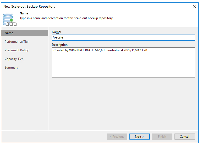
Step 1 Choose Backup Infrastructure. On the displayed page, right-click Scale-out Repositories, and select Add scale-out backup repository from the shortcut menu. On the displayed page, set Name to the name of the scale-out repository.
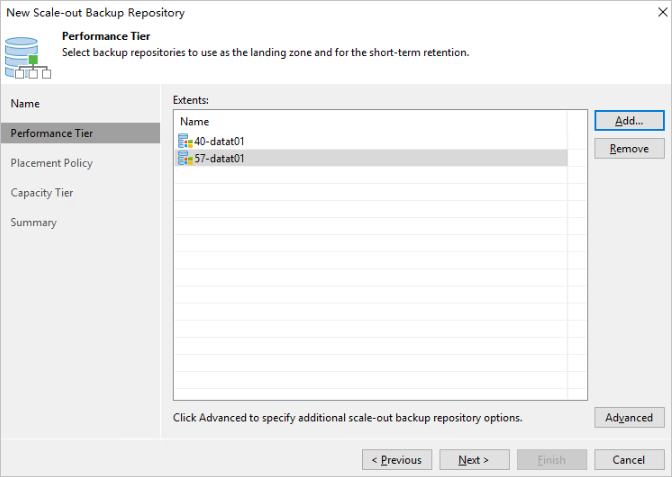
Step 2 On the Performance Tier tab page, add the configured backup repositories.
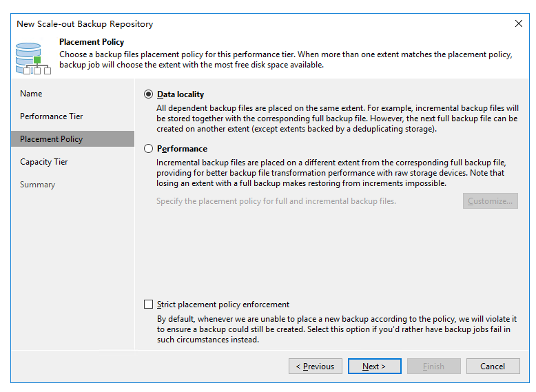
Step 3 On the Placement Policy page, specify how backup files are stored on the performance expansion area of the scale-out backup repository.
- Data locality: Select Data locality if you want to store backup files that belong to the same backup chain together or you need to use synthetic full backup with Fast Clone. Select Data locality for this solution.
- Performance: Select Performance if you want to store full and incremental backup files to different extents of the scale-out backup repository.
Step 4 Click Apply and perform operations as prompted.
—-End
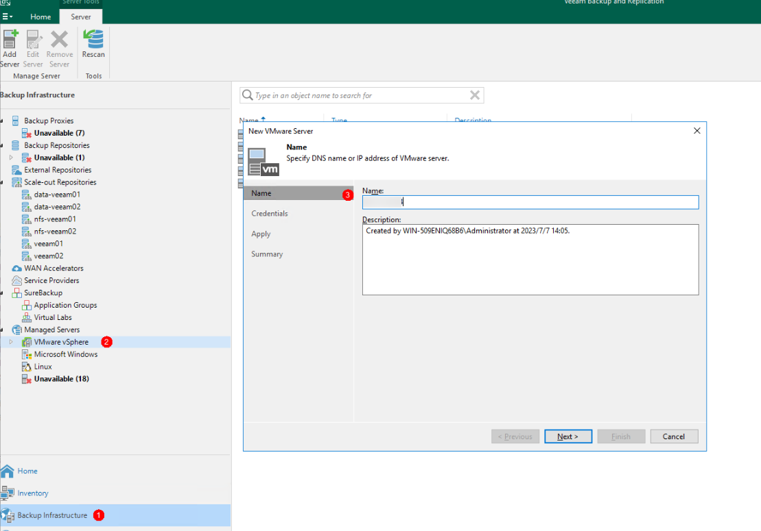
4.5.6.5 Configuring VMware vSphere
Step 1 On the Backup Infrastructure page, right-click VMware vSphere and choose Add server from the shortcut menu. Enter the IP address in Name and click Next.
Step 2 On the Credentials page, add the username and password and click Apply. Perform subsequent operations as prompted.
—-End
4.5.6.6 Configuring VM Backup Jobs
Step 1 On the Home page, choose Jobs > Backup. From the drop-down list, click Virtual machine. On the Name page that is displayed, specify Name and click Next.
Step 2 Click Add to add the VM to be backed up and click Next.
Step 3 On the Storage page, retain the default setting Automatic selection for Backup proxy and select the previously configured scale-out backup repository for Backup repository.
Step 4 Click Advanced. On the Storage tab page, deselect Enable inline data deduplication (recommend) to disable the deduplication function of the backup software. Set Compression level to None to disable the compression function of the backup software. Click OK. Perform subsequent operations as prompted.
—-End
4.5.7 Executing Backup
4.5.7.1 First Full Backup
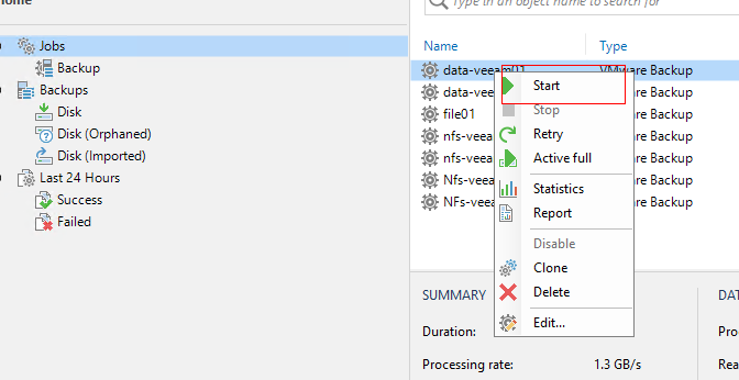
On the home page, right-click the VM backup task and choose Start from the shortcut menu to perform the first full backup.
4.5.7.2 Multiple Full Backups
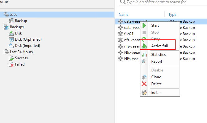
On the home page, right-click the VM backup task and choose Active full from the shortcut menu to perform subsequent full backups.
4.5.8 Performing Restoration
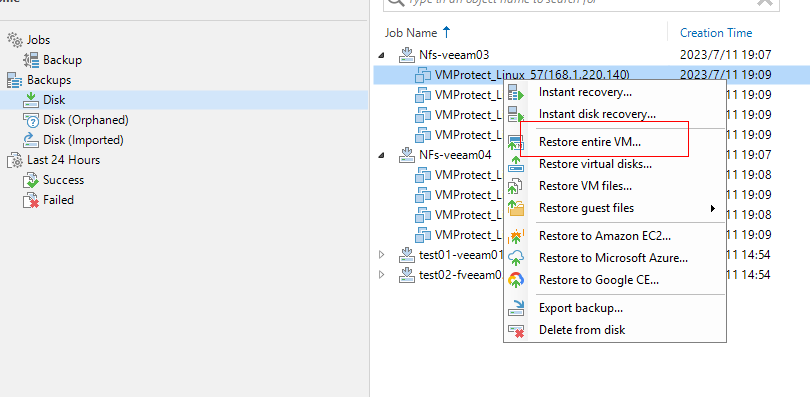
Step 1 Find the VM copy that has been backed up, right-click it, choose Restore entire VM from the shortcut menu, and click Next.
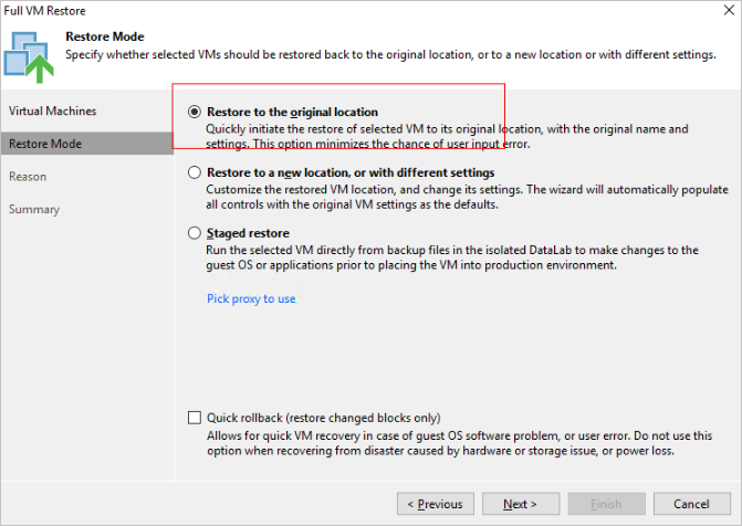
Step 2 Select Restore to the original location to restore data to the original location, and click Next. Perform subsequent operations as prompted.
4.6 Configuring Veeam Synthetic Full Backup
Step 1 Log in to the prepared VM and embed the same amount of data in the five data disks.
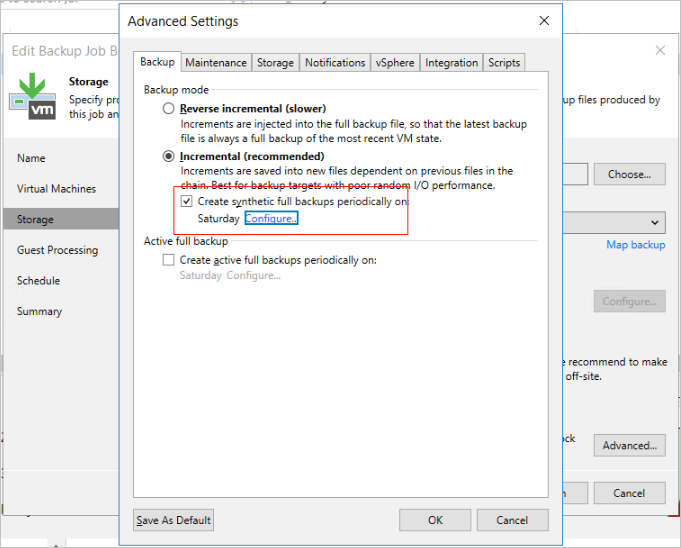
Step 2 Configure the backup environment for Veeam. For details, see 4.5.5 Configuring the Backup Environment (Backup Repository). When performing configuration on the Storage tab page for a VM backup job, click Advanced. On the Backup tab page of the displayed dialog box, set Backup mode to Incremental (recommended), select the Create synthetic full backups periodically on check box, and click Configure to specify the time for performing synthetic full backup.
Step 3 Perform the initial full backup and record the test result.
Step 4 Execute five incremental backups with 5% data changed between two backups.
Step 5 Before the sixth incremental backup, ensure that 5% data is changed since last backup. After the incremental backup is executed the next day, the synthetic full backup is automatically performed.
—-End

If the gateway server uses Linux source deduplication and Fast Clone is required for synthetic full backup, select Use fast cloning on XFS volumes.
5 Best Practice Verification Examples
The following test data in this chapter is obtained based on specific servers and configurations. The backup and restoration performance test result is specific to a single scenario, without adding other functions such as remote replication. The backup and restoration performance in this document may be different from that in the actual production environment. The actual performance is subject to the actual situation.
5.1 Backup and Restoration Bandwidth Performance Test Results
The test data in this section is obtained based on the following model:
- Preset data model: 28 Linux VMs are preset, each with one 50 GB system disk and five 120 GB data disks. A total of 500 GB or 600 GB data is preset for data disks. The deduplication ratio is 1.3:1, and the compression ratio is 2:1.
- Backup policy: Full backup is performed at the first, second, and third backups.
- Incremental data: A 5% data volume change is constructed between backups.
5.1.1 Repository Performance Test Result
In this solution, the typical server configuration (CPU: Intel(R) Xeon(R) Silver 4214R, memory: 256 GB) is used during the test on VM backup performance in the scenario where four gateway servers are deployed. For details about the networking, see 4.3.1 VM Backup Planning Using OceanProtect X8000 (Backup Repository). The performance test scenario is detailed as follows:
- Production environment: Four gateway servers and four ESXi 7.0 are used. Each ESXi 7.0 is configured with four backup proxies. Each backup proxy is configured with 32 CPU cores and 64 GB memory. Each VM contains six disks, including one 50 GB system disk and five 120 GB data disks, and a total of 500 GB or 600 GB data is preset in the data disks. Therefore, there is 17.6 TB data in total for backup of 28 VMs.
- Backup environment: OceanProtect X8000 (all-flash form) is deployed. Four file systems are created, each of which is connected to one gateway server through DataTurbo over an IP network. The low level is selected for OceanStor DataTurbo.
- Veeam backup repository planning: A total of four Veeam backup repositories are configured on Veeam.
- Veeam backup repository: Each mount point is configured as an independent backup repository.
- Veeam job configuration: All VMs to be backed up are evenly distributed to four backup jobs and data is backed up to the four different backup repositories.
- Test model: Full backup for the first, second and third backups, and restoration
Table 5-1 describes the test result.
Table 5-1 Backup and restoration bandwidth performance test result of repositories
Compression Mode | Backup/Restoration Type | Peak Logical Bandwidth for Backup/Restoration (GB/s) | Backup/Restoration Data Volume (TB) | Backup/Restoration Duration (Minute) | Average Backup/Restoration Logical Bandwidth (GB/s) | Reduction Ratio |
|---|---|---|---|---|---|---|
High performance mode | First full backup | 5.566 | 17.6 | 50 | 6.007 | 4.213 |
Second full backup | 7.289 | 17.6 | 43 | 6.985 | 7.820 | |
Third full backup | 7.535 | 17.6 | 43 | 6.985 | 10.968 | |
Restoration | 6.845 | 17.6 | 43 | 6.985 | / | |
High reduction ratio mode | First full backup | 4.555 | 17.6 | 61 | 4.924 | 4.324 |
Second full backup | 7.140 | 17.6 | 49 | 6.130 | 8.112 | |
Third full backup | 7.274 | 17.6 | 50 | 6.007 | 11.490 | |
Restoration | 6.308 | 17.6 | 44 | 6.827 | / |
5.1.2 Scale-Out Repository Performance Test Result
In this solution, the typical server configuration (CPU: Intel(R) Xeon(R) Silver 4214R, memory: 256 GB) is used during the test on VM backup performance in the scenario where four gateway servers are deployed. For details about the networking, see 4.3.2 VM Backup Planning Using OceanProtect X8000 (Scale-Out Backup Repository). The performance test scenario is detailed as follows:
- Production environment: Four gateway servers and four ESXi 7.0 are used. Each ESXi 7.0 is configured with four backup proxies. Each backup proxy is configured with 32 CPU cores and 64 GB memory. Each VM contains six disks, including one 50 GB system disk and five 120 GB data disks, and a total of 500 GB or 600 GB data is preset in the data disks. Therefore, there is 17.6 TB data in total for backup of 28 VMs.
- Backup environment: OceanProtect X8000 (all-flash form) is deployed. Four file systems are created, each of which is connected to one gateway server through DataTurbo over an IP network. The low level is selected for OceanStor DataTurbo.
- Veeam Backup Scale-Out: The Data locality mode is configured. The repositories in each scale-out repository correspond to the file systems on the same controller.
- Veeam backup repository: Each mount point is configured as an independent backup repository.
- Veeam job configuration: All VMs to be backed up are evenly distributed to four backup jobs and data is backed up to the two different scale-out repositories.
- Test model: Full backup for the first, second and third backups, and restoration
Table 5-2 describes the test result.
Table 5-2 Backup and restoration bandwidth performance test result of scale-out repositories
Compression Mode | Backup/Restoration Type | Peak Logical Bandwidth for Backup/Restoration (GB/s) | Backup/Restoration Data Volume (TB) | Backup/Restoration Duration (Minute) | Average Backup/Restoration Logical Bandwidth (GB/s) | Reduction Ratio |
|---|---|---|---|---|---|---|
High performance mode | First full backup | 5.524 | 17.6 | 50 | 6.007 | 4.205 |
Second full backup | 7.515 | 17.6 | 41 | 7.326 | 7.474 | |
Third full backup | 7.534 | 17.6 | 42 | 7.152 | 10.848 | |
Restoration | 6.800 | 17.6 | 44 | 6.827 | / | |
High reduction ratio mode | First full backup | 4.517 | 17.6 | 60 | 5.006 | 4.244 |
Second full backup | 7.405 | 17.6 | 43 | 6.985 | 7.98 | |
Third full backup | 7.501 | 17.6 | 43 | 6.985 | 11.294 | |
Restoration | 6.203 | 17.6 | 47 | 6.391 | / |

- High performance mode: Set Compression mode of the storage pool to High performance and the file system application type to Performance_Prioritized_Mode_enhanced.
- High reduction ratio mode: Set Compression mode of the storage pool to High reduction ratio and the file system application type to Reduction_Prioritized_Mode_enhanced.
- Reduction Ratio indicates the ratio of the amount of user data written into the storage pool to the used capacity of the storage pool.
- The actual data reduction ratio is closely related to the data model and backup policy. The test results are based on the preceding backup policy and data model.
- The backup and restoration bandwidths are related to the end-to-end (E2E) hardware configurations. The test result in this section does not indicate the maximum backup and restoration capabilities of OceanProtect X8000.
5.2 Linear Relationship in Backup Performance in the Case of Different Quantities of Gateway Servers
5.2.1 Repository Performance Test
In this solution, the typical server configuration (CPU: Intel(R) Xeon(R) Silver 4214R, memory: 256 GB) is used during the test on VM backup performance in the scenario where four gateway servers are deployed. For details about the networking, see 4.3.1 VM Backup Planning Using OceanProtect X8000 (Backup Repository). The performance test scenario is detailed as follows:
- Production environment: Four gateway servers and four ESXi 7.0 are used. Each ESXi 7.0 is configured with four backup proxies. Each backup proxy is configured with 32 CPU cores and 64 GB memory. Each VM contains six disks, including one 50 GB system disk and five 120 GB data disks, and a total of 500 GB or 600 GB data is preset in the data disks. Therefore, there is 17.6 TB data in total for backup of 28 VMs.
- Backup environment: OceanProtect X8000 (all-flash form) is deployed. Four file systems are created, each of which is connected to one gateway server through DataTurbo over an IP network. The low level is selected for OceanStor DataTurbo.
- Veeam backup repository planning: A total of four Veeam backup repositories are configured on Veeam.
- Veeam backup repository: Each mount point is configured as an independent backup repository.
- Veeam job configuration: All VMs to be backed up are evenly distributed to four backup jobs and data is backed up to the four different backup repositories.
- Test model: Full backup for the first, second and third backups, and restoration. A 5% data volume change is constructed between backups.
Table 5-3 describes the test result.
Table 5-3 Backup bandwidth performance test result in the single-gateway-server scenario
Compression Mode | Backup/Restoration Type | Peak Backup/Restoration Bandwidth (GB/s) | Backup/Restoration Data Volume (GB) | Backup/Restoration Duration (Minute) | Average Backup/Restoration Bandwidth (GB/s) |
|---|---|---|---|---|---|
High performance mode | First full backup | 1.518 | 4505 | 47 | 1.598 |
Second full backup | 1.951 | 4505 | 44 | 1.706 | |
Third full backup | 1.969 | 4505 | 44 | 1.706 | |
Restoration | 1.761 | 4505 | 45 | 1.669 | |
High reduction ratio mode | First full backup | 1.272 | 4505 | 59 | 1.273 |
Second full backup | 1.731 | 4505 | 55 | 1.365 | |
Third full backup | 1.990 | 4505 | 54 | 1.390 | |
Restoration | 1.595 | 4505 | 45 | 1.669 |
The backup bandwidth in the case of different numbers of gateway servers is estimated based on the following E2E backup bandwidth performance, which is obtained through backup performance tests on multiple gateway servers.
Table 5-4 E2E backup bandwidth performance test result in high reduction ratio mode in scenarios with multiple gateway servers deployed
Number of Gateway Servers | E2E Backup Bandwidth (GB/s) |
|---|---|
1 | 1.390 |
2 | 2.780 |
3 | 4.312 |
4 | 6.007 |

The backup performance increases linearly as the number of gateway servers increases. You can estimate the number of gateway servers to be deployed by dividing the customer-required performance by the performance of a single gateway server.
5.2.2 Scale-Out Repository Performance Test
In this solution, the typical server configuration (CPU: Intel(R) Xeon(R) Silver 4214R, memory: 256 GB) is used during the test on VM backup performance in the scenario where four gateway servers are deployed. For details about the networking, see 4.3.2 VM Backup Planning Using OceanProtect X8000 (Scale-Out Backup Repository). The performance test scenario is detailed as follows:
- Production environment: Four gateway servers and four ESXi 7.0 are used. Each ESXi 7.0 is configured with four backup proxies. Each backup proxy is configured with 32 CPU cores and 64 GB memory. Each VM contains six disks, including one 50 GB system disk and five 120 GB data disks, and a total of 500 GB or 600 GB data is preset in the data disks. Therefore, there is 17.6 TB data in total for backup of 28 VMs.
- Backup environment: OceanProtect X8000 (all-flash form) is deployed. Four file systems are created, each of which is connected to one gateway server through DataTurbo over an IP network. The low level is selected for OceanStor DataTurbo.
- Veeam Backup Scale-Out: The Data locality mode is configured. The repositories in each scale-out repository correspond to the file systems on the same controller.
- Veeam backup repository: Each mount point is configured as an independent backup repository.
- Veeam job configuration: All VMs to be backed up are evenly distributed to four backup jobs and data is backed up to the two different scale-out repositories.
- Test model: Full backup for the first, second and third backups, and restoration. A 5% data volume change is constructed between backups.
Table 5-5 describes the test result.
Table 5-5 Backup bandwidth performance test result in the single-gateway-server scenario
Compression Mode | Backup/Restoration Type | Peak Backup/Restoration Bandwidth (GB/s) | Backup/Restoration Data Volume (GB) | Backup/Restoration Duration (Minute) | Average Backup/Restoration Bandwidth (GB/s) |
|---|---|---|---|---|---|
High performance mode | First full backup | 1.499 | 4505 | 47 | 1.598 |
Second full backup | 1.960 | 4505 | 40 | 1.877 | |
Third full backup | 1.911 | 4505 | 42 | 1.788 | |
Restoration | 1.721 | 4505 | 46 | 1.632 | |
High reduction ratio mode | First full backup | 1.078 | 4505 | 62 | 1.211 |
Second full backup | 1.772 | 4505 | 46 | 1.632 | |
Third full backup | 1.835 | 4505 | 45 | 1.669 | |
Restoration | 1.457 | 4505 | 48 | 1.564 |
The backup bandwidth in the case of different numbers of gateway servers is estimated based on the following E2E backup bandwidth performance, which is obtained through backup performance tests on multiple gateway servers.
Table 5-6 E2E backup bandwidth performance test result in high reduction ratio mode in scenarios with multiple gateway servers deployed
Number of Gateway Servers | E2E Backup Bandwidth (GB/s) |
|---|---|
1 | 1.669 |
2 | 3.338 |
3 | 5.084 |
4 | 6.985 |

The backup performance increases linearly as the number of gateway servers increases. You can estimate the number of gateway servers to be deployed by dividing the customer-required performance by the performance of a single gateway server.
5.3 Veeam Synthetic Full Backup Performance
In this solution, the typical server configuration (CPU: Intel(R) Xeon(R) Silver 4214R, memory: 128 GB) is used during the test on VM backup performance in the scenario where four gateway servers are deployed. For details about the networking, see 4.3.2 VM Backup Planning Using OceanProtect X8000 (Scale-Out Backup Repository). The performance test scenario is detailed as follows:
- Production environment: Four gateway servers and eight ESXi 7.0 are used. Each ESXi 7.0 is configured with four backup proxies. Each backup proxy is configured with 32 CPU cores and 64 GB memory. Each VM contains six disks, including one 50 GB system disk and five 120 GB data disks, and a total of 500 GB or 600 GB data is preset in the data disks. Therefore, there is 40 TB data in total for backup of 64 VMs.
- Backup environment: OceanProtect X8000 (all-flash form) is deployed. Four file systems are created, each of which is connected to one gateway server through DataTurbo over an IP network.
- Veeam backup scale-out: The Data locality mode is configured. The repositories in each scale-out repository correspond to the file systems on the same controller.
- Veeam backup repository: Each mount point is configured as an independent backup repository.
- Veeam job configuration: All VMs to be backed up are evenly distributed to four backup jobs and data is backed up to the two different scale-out repositories.
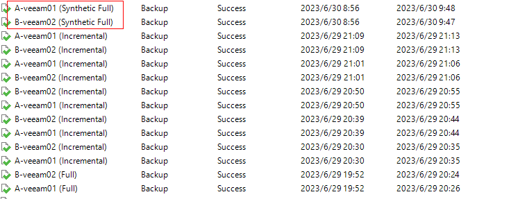
- Test model: First full backup, five incremental backups, and synthetic full backup. A 5% data volume change is constructed between backups.
Table 5-7 describes the test result.
Table 5-7 Performance test result of synthetic full backup
Compression Mode | Backup Type | Peak Logical Bandwidth of Backup (GB/s) | Backup Data Volume (TB) | Backup Duration (Minute) | Synthetic Full Backup Duration (Minute) | Average Backup Bandwidth (GB/s) | Synthetic Full Backup Bandwidth (GB/s) |
|---|---|---|---|---|---|---|---|
High reduction ratio mode | First full backup | 3.829 | 40 | 168.29 | / | 4.056 | / |
First incremental backup | 3.84 | 1.76 | 9.595 | / | 3.136 | / | |
Second incremental backup | 3.78 | 1.54 | 9.4 | / | 2.798 | / | |
Third incremental backup | 3.801 | 1.54 | 9.265 | / | 2.839 | / | |
Fourth incremental backup | 3.635 | 1.56 | 9.73 | / | 2.736 | / | |
Fifth incremental backup | 3.71 | 1.56 | 9.79 | / | 2.7 | / | |
Synthetic full backup | 66.051 | 40 | 27.78 | 21.43 | / | 31.856 |