OceanProtect 1.6.0 Backup Storage Solution Best Practice (Integration with Commvault)
Interoperability Test Report

Axians Global All Rights Re
1. Solution Overview
The backup storage solution provides a backup system with software and hardware deployed independently. It includes the backup software, backup agent, backup management server, backup storage server, and backup storage. Figure 1-1 shows the solution architecture.
Figure 1-1 Backup storage solution architecture
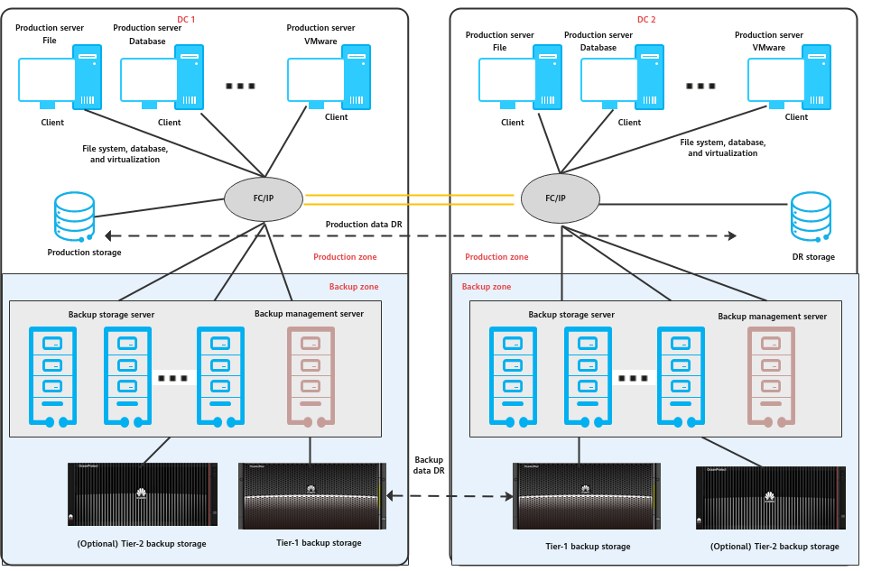
Components
- Mainstream backup software includes Veritas NetBackup, Veeam, Commvault, and more.
- The backup management servers manage components in the backup system and are used to create, execute and schedule backup jobs and configure backup policies. The backup management servers can be deployed independently or together with media servers.
- Installed on protected application production servers and VMs, the backup agent client responds to backup job scheduling of the backup management servers, collects and manages data to be protected, and transmits the data to the backup storage servers.
- The backup storage servers (also called media servers) are independently deployed and respond to job scheduling of the backup management servers. The backup storage servers process backup data flows and manage backup data transmission and storage devices of backup data. Some vendors also provide backup data deduplication and compression capabilities on backup storage servers.
- Backup storage, which is connected to the backup storage servers, is used to receive and store backup data. Some backup storage devices also provide deduplication and compression capabilities. Based on service requirements, backup storage can be designed as two levels. Tier-1 backup storage provides fast and efficient backup and data restoration capabilities, delivering optimal backup and restoration performance. The cost of tier-1 backup storage is high, and data deduplication and compression are important. Tier-2 backup storage stores data for a long term at a low cost. Backup copies stored for more than a certain period of time are migrated to tier-2 backup storage, achieving the optimal comprehensive retention cost. Common backup storage types include backup storage, general-purpose storage, virtual tape libraries (VTL), object storage, and tape libraries.
Solution Description
- During backup, the backup management server delivers a backup scheduling command to the backup agent so that the backup agent collects and transmits data based on the specified backup policy. The backup storage server processes the data transmitted by the backup agent, writes the data to the backup storage in a certain format, and records the index.
- Due to the performance upper limit of a single backup storage server, if the processing performance is insufficient, scale-out of backup storage servers is supported.
- Backup data replication: Based on compliance and data security requirements, remote disaster recovery (DR) is also required for backup data. Data can be replicated and transmitted through the backup storage server or tier-1 backup device.
- Long time retention (LTR) of backup data: The LTR solution is a suitable choice if customers want to retain backup copies for a long time and require quick restoration. According to the policy, the most recent copies are stored on tier-1 backup media to provide quick backup, quick access, and restoration. Copies that need to be stored for a long time are stored on tier-2 backup media with lower cost. The combination of the two types of storage media helps achieve the optimal comprehensive retention cost.
This document describes the backup storage solution based on the OceanProtect Backup Storage integrating Commvault.
Solution Introduction
The backup storage solution in which Huawei OceanProtect Backup Storage integrates Commvault can be used to back up application systems, replicate backup copies, and implement LTR-based tiering.
2. Components
2.1.1 Commvault Backup Software
Commvault can manage data in file systems, email systems, databases, VMs, application systems, desktop computers, and online storage systems:
- Data backup and restoration
- Online storage device snapshot management
- Continuous data replication
- Content search
- Data analysis
- Deduplication
- Encryption of backup/archive data
Table 2-1 lists the main functions and advantages of Commvault.
Table 2-1 Main functions and advantages of Commvault
Item | Sub-item | Requirements |
|---|---|---|
File system | Unix and Linux | The backup system must support the backup of AIX and HP-UX file systems. |
The backup system must support the backup of Red Hat Enterprise Linux/CentOS, SUSE Linux, and Ubuntu file systems. | ||
The backup system must support the backup of Solaris file systems. | ||
Windows | The backup system must support the backup of Windows file systems. | |
Operating system (OS) | OS | The backup system must support the backup of Windows, SUSE, and Red Hat OSs. |
Application type | Database | The backup system must support the backup of Oracle, SAP, SQL Server, Sybase, MySQL, DB2, PostgreSQL, and Informix application clients. |
Virtualization | The backup system must support the backup of VMware, Hyper-V, Citrix, and FusionCompute and the restoration of individual VMs and files. | |
Other applications | The backup system must support the backup of Exchange, SharePoint, and ERP application clients. | |
Backup system | NDMP backup | The backup software must support the NDMP backup mode. |
Workflow | The backup software must support customized workflow. | |
Backup index | The internal index library of the backup software employs the distributed 2-tier mechanism: The tier-1 indexes manage the detailed backup records and are stored on multiple media servers while the tier-2 indexes manage a small amount of job information and are stored on the backup management server. | |
Deduplication |
| |
Data encryption | Backup data is stored in a proprietary format instead of a standard format such as .tar and .cpio. Backup data can be encrypted using at least three encryption algorithms, including Advanced Encryption Standard (AES) and Triple Data Encryption Standard (3DES). | |
Graphical user interface (GUI) |
| |
Resumable backup | Resumable backup and restoration of files, Oracle databases, and email systems is supported. The system automatically resumes a backup/restoration operation from the breakpoint without manual intervention. | |
Restoration of individual Oracle tables | RMAN can be used to back up Oracle data and restore individual Oracle tables without using any scripts. | |
Restoration of individual emails | In addition to database-level backup for Exchange Server, restoration of individual emails is supported. Email-level backup and restoration are supported for Lotus Domino. | |
Fine-grained restoration of VMs |
| |
Hardware snapshot | Hardware snapshot functions provided by mainstream storage vendors, including EMC, IBM, DELL, HDS, HP, NetApp, and Huawei, can be invoked. | |
Infrastructure | System architecture | A complete backup system comprising management, business, and client components, backup networks, and backup media, is provided. The SAN- or NAS-based centralized and unified backup mode and remote backup of data in multiple remote sites are supported. |
Networking mode | LAN-based, LAN-free, and Server-free networking modes are supported. | |
Capacity expansion | Scalability | Capacity expansion can be performed based on a capacity or function license. Backup media servers can be added to improve backup performance and the backup storage capacity can be expanded. |
Reliability | Failover and load balancing are supported. | Redundant backup paths can be set and can be automatically managed for load balancing. Backup media servers, media drives, and media can be automatically selected so that backup jobs can be efficiently completed. Backup jobs can be executed on multiple backup media servers for load balancing. |
Centralized management of multiple backup domains | The backup system is able to centrally manage multiple backup domains. The backup domain at the headquarters periodically collects the index records of all backup domains, enabling centralized data query, restoration, and report within multiple data centers. | |
Readiness check | The backup system can be checked periodically or before each backup operation for any software, hardware, and system issues, and a system check report can be provided to ensure the reliability of the backup system. | |
Automated restoration drill | The GUI supports simplified and automated drill process of restoring files and applications to different hosts to verify the restorability of backup data. | |
GUI | GUI-based centralized configuration management platform of backup services is provided. A unified report and alarm management platform is provided. |
2.1.2 OceanProtect Backup Storage
Service Positioning
As the amount, types, and growth rate of data change exponentially, enterprises face increasing data loss risks due to unintentional deletion, viruses, natural disasters, and other network security threats. Therefore, data protection becomes increasingly important.
The OceanProtect Backup Storage features rapid backup and restoration, low resource consumption, and solid resilience, and helps to implement efficient backup and restoration and greatly reduce the total cost of ownership (TCO). It is widely used in government, financial, carrier, healthcare, and manufacturing industries. In addition, it offers easy-to-use management modes and convenient local/remote maintenance modes, significantly decreasing the management and maintenance costs.
The OceanProtect Backup Storage is available in SSD form and HDD form.
- SSD form: The system supports only solid-state drives (SSDs). Both service data and metadata are stored in SSDs.
- HDD form: The system supports both SSDs and hard disk drives (HDDs). Service data is stored in the storage pool composed of HDDs. SSDs only store system metadata. SSDs with superb performance can accelerate access to metadata, improving read/write performance.
Product Highlights
Based on the full-process acceleration and active-active high-reliability architecture, the OceanProtect Backup Storage features rapid backup and restoration, low resource consumption, and solid resilience.
In addition, the OceanProtect Backup Storage provides new features such as source deduplication and deduplicated replication to effectively increase the logical bandwidth and decrease the network resource occupation for customers.
- Rapid backup and restoration
- Full-process acceleration is implemented. The front-end network protocol offload technology reduces the CPU pressure, and the back-end CPU multi-core parallel scheduling is implemented. Dedicated cores are used through grouping and job partitioning, efficiently improving the processing capability of nodes.
- Multiple sequential data flows are aggregated for read and write to greatly improve bandwidth performance. Source deduplication reduces the amount of data to be transmitted over the network and shortens the backup duration.
- The system provides high IOPS performance and can work with mainstream backup software. Backup image data can be accessed immediately, implementing fast utilization of backup data.
- Low resource consumption
- Accurate backup data segmentation, backup data aggregation preprocessing, and multi-layer inline variable-length deduplication are used to increase the logical capacity and reduce the TCO.
- Data flow features can be identified. Compression after combination, high-performance predictive encoding, and byte-level compaction are used to improve the data reduction ratio.
- Source deduplication and deduplicated replication are used to reduce network bandwidth costs.
- Solid resilience
- The active-active hardware architecture design ensures that ongoing backup jobs can be switched over within seconds if a single controller is faulty, ensuring uninterrupted backup jobs.
- Protocol encryption, replication link encryption, array encryption, secure snapshots, and write once read many (WORM) are used to ensure security and availability of copies.
2.2 Architecture
2.2.1 Overall Solution Architecture
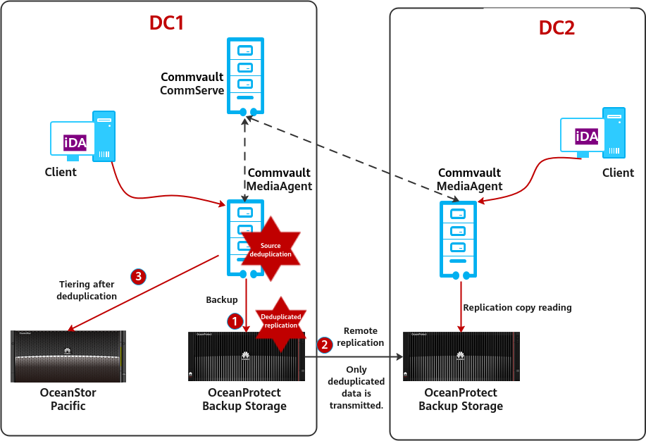
Figure 2-1 Overall architecture of the OceanProtect Backup Storage + Commvault solution
Description
- Backup and restoration
- OceanProtect supports multiple protocols: DataTurbo (IP, recommended), DataTurbo (Fibre Channel (FC for short), recommended), standard NFS/CIFS, and SAN.
- During backup, you are advised to enable OceanProtect deduplication and disable deduplication and compression on the backup software to achieve the optimal deduplication and compression effect.
- Remote replication
- The remote replication (HyperReplication) of the OceanProtect Backup Storage is preferred. When storage-layer replication is used, the data transmission path is shortened from « storage > backup software > storage » to « storage > storage », improving transmission efficiency and reducing the overhead of backup media servers.
- When a Replica Library created on Commvault is used to integrate the OceanProtect Backup Storage, replication copies can be directly managed in the remote system of Commvault.
- OceanProtect 1.2.0 supports deduplicated replication. Only deduplicated copies are transmitted to the remote site, effectively reducing replication bandwidth usage.
- In OceanProtect 1.3.0, copy-based restoration after remote replication can be performed without splitting the replication pair.
- Tiering for LTR
- After the Commvault MediaAgent deduplicates and tiers data, LTR copies are stored in the OceanStor Pacific object storage or public cloud storage.
- The copies tiered from Commvault to the object storage or public cloud storage can be directly used for data restoration.
2.2.2 Solution Architecture
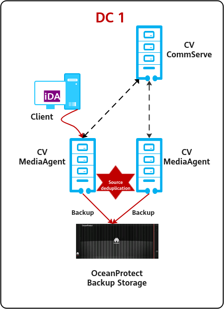
Figure 2-2 Solution architecture
Overview
- CV components
- CommServe (CS): a management server, which manages data backup, archive, and restoration. The CommServe manages all software components. It contains a SQL Server database that stores all configurations, security attributes, operation history, and metadata. In a Commvault backup domain, there can be only one CommServe which can be installed on a physical machine (PM), virtual machine (VM), or cluster and supports Windows OS.
- MediaAgent (MA): a media agent server, which manages data transmission and data storage libraries such as disk libraries, tape libraries, and cloud storage. The CS directs and coordinates MediaAgent to execute jobs. Multiple MediaAgents can be deployed in a Commvault backup domain to improve the performance. MediaAgent can be installed on a PM, VM, or cluster and supports Windows, Linux, and Unix OSs.
- iDataAgent (iDA): a client agent installed on the client computer or agent server, which secures, manages, and transfers data. Under the dispatching of the CS, iDA can directly transmit data to MediaAgent. There are various agents for managing different types of data such as backup agents for Windows and Linux file systems and Oracle databases. iDA can be installed in a PM, VM, or cluster.
- Integration solution
When the Commvault + OceanProtect backup storage solution is used, the OceanProtect backup storage serves as the backup storage media to integrate with Commvault as backup software. With all existing backup functions of Commvault supported, the data can be written from the client to the OceanProtect backup storage.
- Integration protocol
Commvault supports multiple backup media such as SAN, NAS, object storage, and tape libraries. Protocols such as Fibre Channel, iSCSI, NFS, CIFS, and S3 are supported.
The OceanProtect backup storage supports multiple protocols such as DataTurbo and CIFS/NFS. DataTurbo is a Huawei proprietary NAS protocol that supports source deduplication. FC SAN is used only in a scenario where the SAN network on the live network cannot be replaced with an IP network.
- Deduplication and compression
- When Commvault uses a front-end capacity or client license, Commvault deduplication is disabled, and only the deduplication and compression features of OceanProtect are used, delivering an optimal deduplication ratio. This solution is recommended and applies to mainstream scenarios.
- When Commvault uses a back-end capacity license, Commvault deduplication is enabled. In this case, the deduplication and compression for the second time performed on OceanProtect deliver a low data reduction ratio. Commvault deduplication is enabled to reduce the Commvault license cost.
2.2.3 Architecture of the Backup Copy Replication Solution
There are two backup copy replication solutions.
- Backup software-based replication. Data is read by the backup software, replicated by backup servers, and written to the backup storage by the remote backup software.
- Backup storage-based replication. Data is directly replicated from the local backup storage system to remote backup storage system and can be identified by the remote backup software for further use.
Backup storage-based replication is preferred with shorter data I/O path and lower read/write performance overhead of backup software replication.
The following figure shows the typical replication network between Commvault and the OceanProtect backup storage.
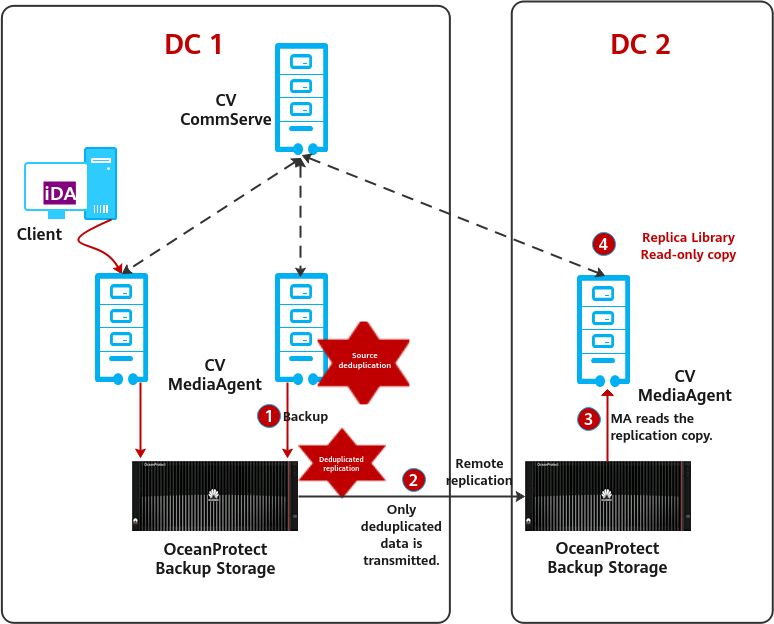
Figure 2-3 Replication network between Commvault and the OceanProtect backup storage
Overview
- One-to-one, one-to-many, and many-to-one replication networks are supported.
- When the deduplication-based replication of the OceanProtect backup storage is used, only deduplicated data is transmitted, saving the replication bandwidth.
- The OceanProtect backup storage integrates Commvault. The file system at the target end replicated by the OceanProtect backup storage is mounted to the target MediaAgent, and is used to create a Replica Library in read-only mode.
- When restoration is required, you can select the target MediaAgent on Commvault CommServe, and MediaAgent automatically finds and restores the required data in the file system of the target end.
2.2.4 Tiering Solution Architecture
Figure 2-4 Tiering solution architecture
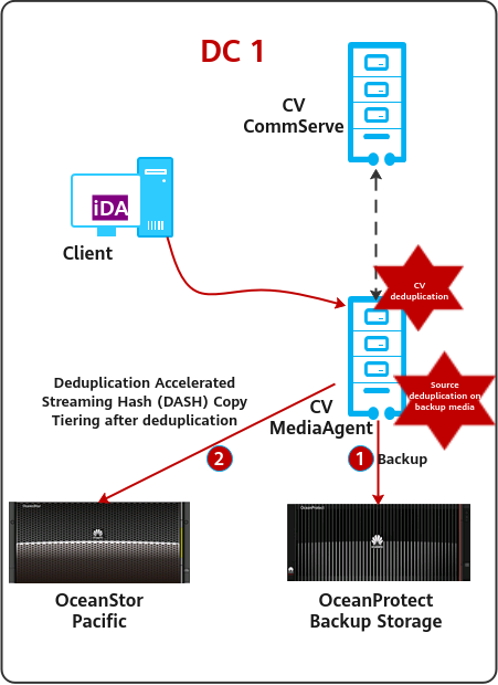
Overview
Data in OceanProtect is tiered to the OceanStor Pacific object storage or public cloud storage using CV. Data is replicated to the OceanStor Pacific object storage using the DASH Copy function of CV.
- Production data is backed up to OceanProtect backup storage for short-term retention.
- DASH Copy of CV is used to tier data to the OceanStor Pacific object storage. Data can be tiered after deduplication for LTR
- Retention policies can be configured on CV for tiered copies. Copies on the OceanStor Pacific object storage can be directly used for restoration.
- CV supports mainstream S3 object storage and public cloud storage.
- For tiered copies for LTR, enable DASH Copy of CV to provide the post-deduplication tiering capability. Otherwise, AUX Copy without deduplication will be used.
2.2.5 Architecture of the WORM Anti-Tampering Solution
Figure 2-5 Architecture of the WORM anti-tampering solution
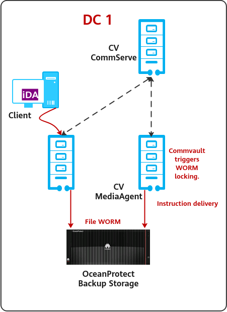
Overview
Ransomware infiltrates a backup system and deletes backup data before encrypting production data and using that to demand ransom. Without backup data available, users have to pay the ransom to get their data back. Therefore, anti-tampering of backup data is particularly important in defense against ransomware attacks.
Solution description
- The OceanProtect backup storage provides a WORM file system at the storage hardware layer. You can set a protection period for backup data to prevent data from being modified or deleted.
- After a backup job is complete, Commvault invokes the OceanProtect interface to lock the backup files and retain them for a certain period.
- The solution uses Commvault to implement WORM protection for specified backup copies at the backup storage hardware layer.
2.3 Constraints
- If the backup software integrates with the OceanProtect Backup Storage through the DataTurbo protocol, a DataTurbo administrator can be created only under the default vStore System_vStore. For this reason, this solution does not apply to multi-vStore scenarios.
3. Planning Suggestions
3.2 Backup Planning for Integrating Applications
3.3 System Backup Capacity and Performance Planning
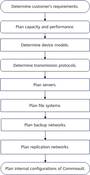
3.1 Planning Process
Select the models of OceanProtect Backup Storage devices and determine the transmission protocols and number of backup media servers required for the entire network based on the customer’s capacity and performance requirements. Then, plan the file systems, backup networks, and replication networks based on the number of servers, transmission protocols, and used features to complete the planning process.
Figure 3-1 Planning process for integrating the OceanProtect with Commvault
3.2 Backup Planning for Integrating Applications
3.2.1 Planning Suggestions for Integrating Production Applications
The OceanProtect backup storage + Commvault solution supports integration with various production application systems for data backup. This document uses typical application integration scenarios as examples.
3.2.1.1 Integration Planning in VMware VM Backup Scenarios
For VMware VM backup, there are three common networking modes, that is, LAN-based, LAN-free, and Server-free.
Figure 3-2 VMware VM backup networking
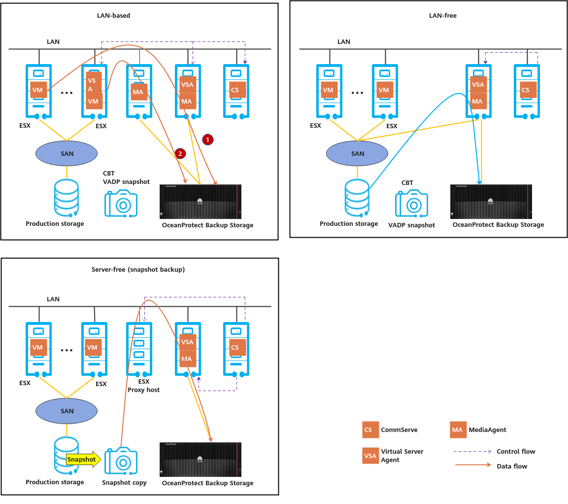
LAN-based
In LAN-based networking mode, backup data is transmitted over an existing LAN. VMware VMs can be backed up in NBD or Hot-Add mode.
- NBD mode: As shown in (1) in Figure 3-2, the Virtual Server Agent (VSA) is deployed on the MediaAgent server. VM files are backed up to the OceanProtect Backup Storage at the back end of the MediaAgent over the LAN. In this mode, the backup efficiency is low.
- Hot-Add mode: As shown in (2) in Figure 3-2, the VMware platform for backup provides one VM for installing the VSA. The VSA VM is used to access other VM files and back up data to the OceanProtect Backup Storage at the back end of the MediaAgent over the LAN.
LAN-free
In LAN-free backup mode, backup data is transmitted over the SAN of the production system, and VMware SAN backup mode is used.
The VSA is installed on the MediaAgent server. During backup, the VSA uses the VADP interface (a VMware standard backup interface) to create VM snapshots and obtains backup data by using the snapshots. The Commvault MediaAgent is connected to the SAN of the production system, reads backup data from the VMware platform over the SAN, and stores the data in the OceanProtect Backup Storage at the back end of the MediaAgent.
Server-free (Snapshot-based Backup)
In Server-free backup mode, backup data is transmitted over the SAN of the production system by using IntelliSnap.
The VSA is installed on the MediaAgent server, and an ESXi proxy host needs to be deployed. (Simplified deployment is supported, and the VSA and MediaAgent share the same physical host.) The ESXi proxy host is connected to the SAN of the production storage. During backup, the VSA schedules the production storage to create snapshots and mounts the snapshots to the ESXi proxy host. Then the VSA backs up data from the ESXi proxy host. In this mode, storage snapshots are used to reduce the impact of the silent time for creating VM snapshots on VMware production services. This networking mode requires that the production storage be compatible with Commvault.
3.2.1.2 Integration Planning in Oracle Database and Host File Backup Scenarios
There are three types of networking modes for Oracle database backup and host file backup, that is, LAN-based, LAN-free, and Server-free.
Figure 3-3 Networking for Oracle database backup and host file backup
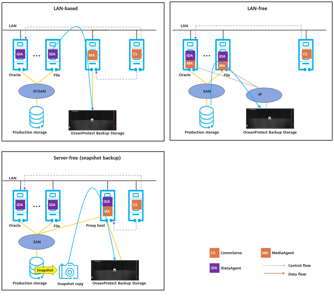
LAN-based
In LAN-based networking mode, backup data is transmitted over LAN.
The Oracle or file client agent iDataAgent (iDA) is installed on the production host. The MediaAgent is independently deployed. During backup, the iDA transmits data over LAN. After being processed by the MediaAgent (such as generating indexes), the data is stored in the back-end OceanProtect Backup Storage. This networking is simple and fully uses the existing network. Some network bandwidth for production services is occupied.
LAN-free
In LAN-free networking mode, backup data is transmitted over SAN.
In the typical networking, the MediaAgent and iDA are installed on the production host, and the backup storage is directly connected to the production host. During backup, data is processed by the iDA and MediaAgent on the production host and directly transmitted to the OceanProtect Backup Storage. This networking has little impact on the existing service network and delivers good backup performance. However, this networking mode increases network investment and has high requirements on production hosts.
Server-free (Snapshot-based Backup)
In Server-free backup mode, backup data is transmitted over the SAN of the production system by using IntelliSnap.
A backup agent iDA is installed on the production host, and an independent MediaAgent is deployed. Another iDA is installed on the MediaAgent as the proxy host of Oracle database or files. The MediaAgent is directly connected to the production SAN and is connected to the production storage. During backup, Commvault schedules the production storage to create snapshots, mounts the snapshots to the proxy host, backs up data from the proxy host, and writes the backup data to the OceanProtect Backup Storage at the back end of the MediaAgent. In this mode, backup data is read from storage hardware snapshots, which has little impact on the production host and existing network. This networking mode requires that the production storage be compatible with Commvault.
3.3 System Backup Capacity and Performance Planning
3.3.1 Network Planning for Different OceanProtect Models
In OceanProtect 1.7.0, a customer can select OceanProtect X3000, X6000, X8000, and X9000 based on different backup capacity and performance requirements. The networking configuration principles of all models must comply with the principles described in 4.3 Configuration Planning for Commvault Integration.
3.3.2 Overall Capacity and Performance Planning
Before planning and designing a backup solution, survey the customer’s production system and plan the backup system according to the following procedure.
- Create a backup policy.
Survey the service systems to be backed up, and create a proper backup policy for each service system based on service requirements. For example, the frequency of full and incremental backups can be once every week and once every day respectively, and the backup data can be retained for one month.
Table 3-1 provides a typical backup policy.
Table 3-1 Typical backup policy
No. | Backup Object | Incremental Backup Interval | Retention Period of Incremental Backup (Day) | Copies of Incremental Backup | Full Backup Interval | Retention Period of Full Backup (Day) | Copies of Full Backup |
|---|---|---|---|---|---|---|---|
1 | VM | Every day | 90 | 87 | Every month | 90 | 4 |
2 | File | Every day | 90 | 77 | Every week | 90 | 14 |
3 | Every day | 365 | 353 | Every month | 365 | 13 | |
4 | Database | Every day | 90 | 77 | Every week | 90 | 14 |
2. Calculate the backup capacity.
Conduct a survey on the production capacity of each service system to be backed up and the data change rate (such as daily, weekly, monthly, and annual change rates). Then, use eDesinger (for carrier users: https://app.huawei.com/unistar/edesigner/#/) or SCT (for enterprise users: https://unistar.huawei.com/unistar/sctnext/#/home/) to calculate the deduplication ratio and post-deduplication capacity.
Table 3-2 provides a typical example of the calculated backup capacity.
Table 3-2 Backup capacity calculation
No. | Site | Backup Object | Initial Capacity (GB) | Capacity Growth Rate | Three-Year Before-deduplication Capacity (GB) | Data Deduplication Ratio | Three-Year Post-deduplication Capacity (GB) |
|---|---|---|---|---|---|---|---|
1 | Data center | VM | 5,000 | 1% per month | 32,177 | 5:1 | 6,435 |
2 | File | 2,500 | 2% per month | 81,206 | 5:1 | 16,241 | |
3 | 1,000 | 2% per month | 33,199 | 8:1 | 4,150 | ||
4 | Database | 5,000 | 1% per month | 112,042 | 3:1 | 37,347 | |
5 | Total: | 13,500 | 258,624 | 64,175 | |||
6 | Remote site 1 | VM | 2,500 | 1% per month | 16,089 | 5:1 | 3,218 |
7 | File | 1,250 | 2% per month | 40,603 | 5:1 | 8,121 | |
8 | Total: | 3,750 | 56,692 | 11,339 | |||
9 | Remote site 2 | VM | 5,000 | 1% per month | 32,177 | 5:1 | 6,435 |
10 | File | 3,000 | 2% per month | 97,447 | 5:1 | 19,489 | |
11 | Total: | 8,000 | 129,624 | 25,924 | |||
12 | Total (all sites): | 25,250 | 444,940 | 101,438 | |||
3. Calculate the backup performance and bandwidth.
You are advised to perform the first full backup after the backup system is delivered for the first time. You need to plan a backup window for the first full backup. A daily backup window needs to be planned for periodic backup or incremental backup based on the backup policy required by the customer. Generally, it is recommended that the periodic full backup of each application system be performed in off-peak hours. In a period, the full and incremental backup jobs of each application system should be executed based on the backup policies.
Table 3-3 provides a typical example of calculating backup performance and bandwidth.
Table 3-3 Example for calculating backup performance and bandwidth
No. | Site | Backup Object | Daily Full Backup Volume After Three Years (GB) | Backup Window (Hour) | Backup Bandwidth (MB/s) |
|---|---|---|---|---|---|
1 | Data center | VM | 7,154 | 4 | 509 |
2 | File | 5,100 | 2 | 725 | |
3 | 2,040 | 1 | 580 | ||
4 | Database | 7,154 | 5 | 407 | |
5 | Remote site 1 | VM | 3,577 | 2 | 509 |
6 | File | 2,550 | 2 | 363 | |
7 | Remote site 2 | VM | 7,154 | 4 | 509 |
8 | File | 6,120 | 3 | 580 |
4. Determine the number of media servers.
For different backup data capacities, five types of media server configurations, from Extra Small to Extra Large, are recommended. More advanced configuration specifications indicate larger backup capacity supported by a single MediaAgent. In an actual project, select a proper type and number of media servers based on the front-end or back-end capacity.
5. Create a replication policy.
If backup copy replication is required for DR, a replication policy must be created. You need to plan the execution window of the replication jobs.
Table 3-4 provides a typical replication policy.
Table 3-4 Replication policy example
No. | Source Site | Target Site | Replication Type | Replication Trigger Type | Replication Time Window |
|---|---|---|---|---|---|
1 | Remote site 1 | Data center | Commvault DASH Copy | Trigger by time, automatic copy | 07:00 to 11:00 |
2 | Remote site 2 | Data center | Commvault DASH Copy | Trigger by time, automatic copy | 07:00 to 11:00 |
3 | Data center | Remote site 2 | Commvault DASH Copy | Trigger by time, automatic copy | 11:00–21:00 |
6. Calculate the replication performance and bandwidth.
Determine the replication time window based on customer requirements. Calculate replication performance requirements based on the volume of data to be replicated.
Table 3-5 provides a typical example of calculating replication bandwidth.
Table 3-5 Typical example of calculating replication bandwidth
No. | Source Site | Target Site | Daily Replication Data Volume (GB) | Replication Time Window (Hour) | Replication Bandwidth (MB/s) |
|---|---|---|---|---|---|
1 | Remote site 1 | Data center | 1,225 | 2 | 174 |
2 | Remote site 2 | Data center | 2,655 | 4 | 189 |
3 | Data center | Remote site 2 | 5,090 | 9 | 161 |
Maximum replication data volume per day per site = ∑(Full backup data volume of all applications/Deduplication rate)
3.3.3 Configuration Planning for the OceanProtect Backup Storage
Backup Capacity and Performance Planning
- Backup capacity calculation
The capacity of OceanProtect X8000 is planned based on the capacity and retention period of the customer’s backup data.

For details about the commercial configuration of OceanProtect X8000, see eDesinger (for carrier users: https://app.huawei.com/unistar/edesigner/#/) or SCT (for enterprise users: https://unistar.huawei.com/unistar/sctnext/#/home) to calculate the backup performance.
- Generally, the backup performance of a backup system is planned based on the backup window and backup capacity of the customer.
Storage Resource Planning
- Disk type planning: Storage pools can be created using SSDs and HDDs. Table 3-6 describes disk type planning.
Table 3-6 Disk type planning
Storage Form | OceanProtect X8000 (all-flash) | OceanProtect X8000 (HDD-based) |
Disk Type | All disks in a storage pool are SSDs. | A storage pool consists of SSDs and HDDs. |
Disk Quantity |
|
|
- Storage capacity planning: The capacity of OceanProtect X8000 is planned based on the customer’s backup data capacity and retention period.
- Compression mode planning: The storage pool supports two compression modes: high reduction ratio (default) and high performance.
With regard to the compression ratio, the high reduction ratio mode outperforms the high performance mode.
- Storage pool planning: A storage pool is a container that stores resources. It provides storage space for all application servers. For core services, RAID-TP is recommended. Table 3-7 describes the protection level policies of storage pools.
Table 3-7 Protection levels of storage pools
Protection Level | Number of Parity Bits | Redundancy and Data Restoration Capability | Maximum Number of Allowed Faulty Disks |
|---|---|---|---|
RAID 6 (default) | 2 | High. Parity data is distributed on different chunks. In each chunk group, the parity data occupies the space of two chunks. RAID 6 is able to tolerate simultaneous failures on two chunks. If three or more chunks fail, RAID 6 protection can no longer be provided. | 2 |
RAID-TP | 3 | High. Parity data is distributed on different chunks. In each chunk group, the parity data occupies the space of three chunks. RAID-TP is able to tolerate simultaneous failures on three chunks. If four or more chunks fail, RAID-TP protection can no longer be provided. | 3 |
File System Planning
- File system planning: Table 3-8 describes the key parameters that are used for file system planning.
Table 3-8 File system planning
Parameter | Description |
|---|---|
Capacity | The capacity of a file system is planned based on actual services. |
Quantity | See 3.3.4 Commvault Deployment Planning. Plan this parameter based on actual service requirements. |
Application type |
|

When the Performance_Global_Mode or Reduction_Global_Mode application type is used, you are advised to create concurrent backup jobs continuously before backup or select more than two backup jobs each time to maximize the performance.
- File system sharing: OceanProtect X8000 provides CIFS, NFS, and DataTurbo shares. DataTurbo is used for file system sharing in this solution, for SourceDedupe to work. For details about the OS versions and backup software versions supported by the DataTurbo client, see the compatibility query website.
https://info.support.huawei.com/storage/comp/#/oceanprotect
Network Planning
- Planning physical ports
- Quantity planning: Plan the quantity of required NICs and ports based on the backup network bandwidth requirements.
- Configuration planning: OceanProtect X8000 is a dual-controller device. To ensure reliability, the planned NICs must be evenly distributed to controllers A and B.
- Planning logical ports
- Quantity planning: Logical ports are created for running NAS services. You are advised to configure at least one logical port for each physical port.
- Configuration planning: OceanProtect X8000 is a dual-controller device and consists of controllers A and B. When mounting a file system, you are advised to use the logical port of controller A for the file system of controller A and the logical port of controller B for the file system of controller B.

To achieve a good deduplication effect, you are advised to disable the deduplication and compression functions of backup software and disable the compression and encryption functions of applications to be backed up. For example, disable compression and encryption of Oracle RMAN.
3.3.4 Commvault Deployment Planning
Backup Network Planning
As shown in 2.2.2 Solution Architecture, the OceanProtect Backup Storage only stores backup data in the entire backup system, but does not participate in the control and scheduling of backup and restoration services. The services are concentrated on the read and write interactions of the Commvault MediaAgent host. Therefore, you need to plan the entire backup system based on the Commvault official documentation to ensure that the performance meets the expectation.
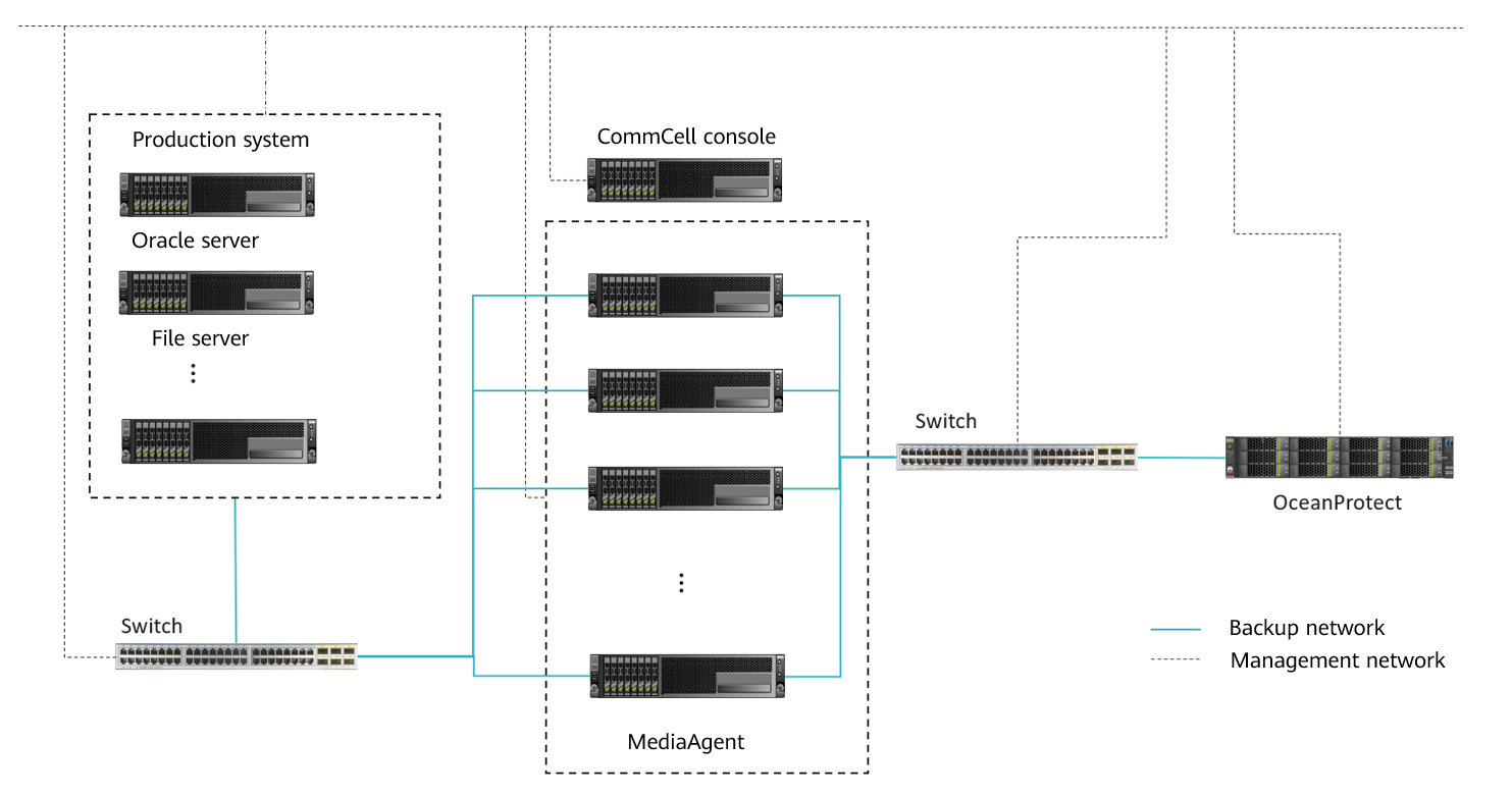
In most non-virtualization backup services, the backup agent is deployed on the production host and sends data to the MediaAgent. The backup agent can be deployed as required.
Figure 3-4 Networking diagram in non-virtualization backup scenarios
In common VMware backup scenarios using Commvault, there are three transmission modes. The Access Node reads production data, and the MediaAgent transmits backup copy data to the OceanProtect Backup Storage. Perform deployment based on service requirements. The transmission mode does not affect the interaction between the backup system and the OceanProtect Backup Storage.
NBD mode: This mode can be used for any infrastructure configuration. The only requirement is that the Access Node must be connected to the VMware host network. However, the data transmission speed on the LAN is slow and the application scenario is rare. Therefore, you are advised to co-deploy the Access Node and MediaAgent.
Figure 3-5 Networking diagram of VMware virtualization backup in NBD mode

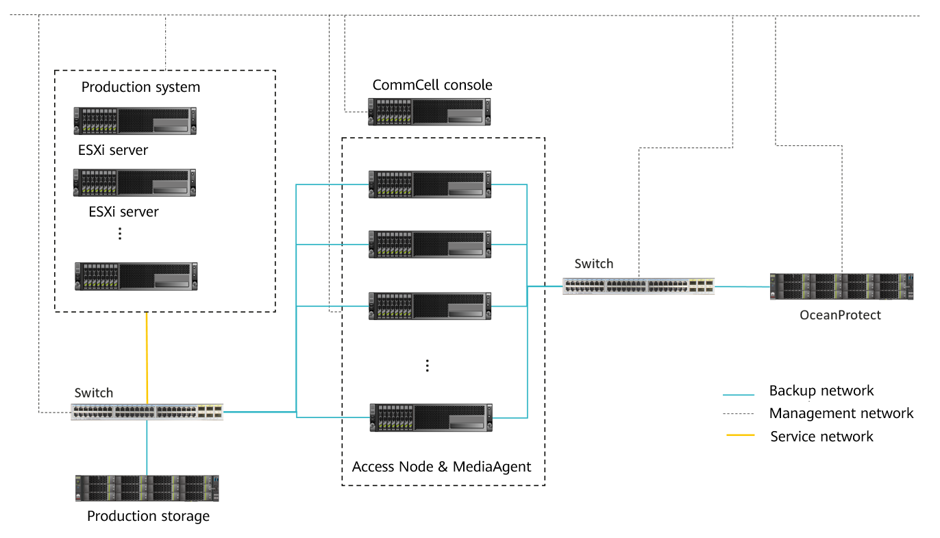
SAN mode: In this mode, Commvault reads data from or writes data to the storage system where the VM data resides. It is recommended that the Access Node and MediaAgent be deployed on the same physical host. The host must be able to directly read data from the storage system of the production system.
Figure 3-6 Networking diagram of VMware virtualization backup in SAN mode
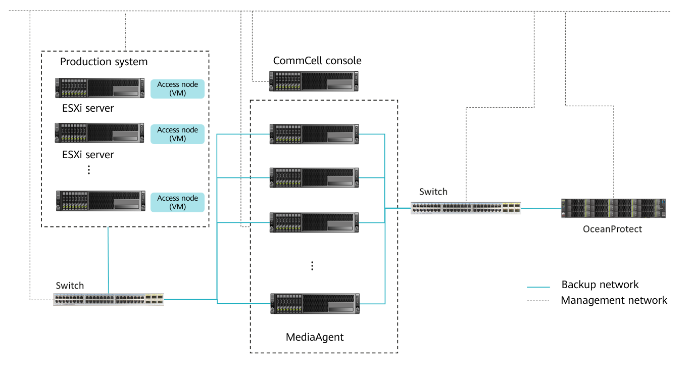
Hot-Add mode: This mode is second only to the SAN mode in terms of efficiency, but its performance is better than that of the NBD mode. If the role of a VMware backup proxy needs to be assigned to virtual hosts, the Hot-Add mode is recommended.
Figure 3-7 Networking diagram of VMware virtualization backup in Hot-Add mode
Commvault MediaAgent Planning
For example, if the DataTurbo protocol is used to integrate the SourceDedupe feature and the backup software, the Commvault backup software and OceanStor DataTurbo must be deployed on the MediaAgent.
- Server requirements: The backup capability of each MediaAgent depends on the server type. For details about the bandwidth capability of each server type, see the related Commvault documentation. Plan the number of servers based on the backup network bandwidth. For details about DataTurbo’s requirements on servers, see « Checking Backup Server Configurations » in the OceanProtect Backup Storage 1.6.0-1.7.0 & V200R001 SourceDedupe User Guide.
- Deployment requirements: To achieve higher performance, you are advised to deploy the CommServe and MediaAgent separately.
- NIC requirements: A MediaAgent is connected to both the production system and backup storage devices. Both the front- and back-end NICs must meet the backup bandwidth requirements to avoid bottlenecks.
- Front-end network: It is used to establish connections with the production environment. To achieve the backup capability of each MediaAgent, the front-end network should be properly configured to prevent it from becoming a bottleneck. For example, if the capability of a single MediaAgent is evaluated as 3.3 GB/s, prepare 4 x 10GE ports for the front-end network, which can be adjusted based on the MediaAgent capability in actual tests.
- Back-end network: This solution uses the SourceDedupe feature. Therefore, the back-end network of the MediaAgent does not need to have the same configuration as the front-end network. You are advised to configure 2 × 10GE ports (one connected to controller A and the other connected to controller B of OceanProtect X8000) on each MediaAgent.
- The following figure shows the networking when the SAN transmission mode is used for the VMware application backup and two MediaAgents are used. The number of physical links to the production system is determined by the capability and number of MediaAgents. The physical bandwidth for connecting to OceanProtect is calculated as follows: Number of MediaAgents × 2 × 10GE. The DataTurbo plug-in is used to mount file systems.
Figure 3-8 Networking diagram of OceanProtect X8000 and Commvault for backing up VMware applications in SAN transmission mode (all hosts in the figure are connected to the management network)
Commvault Library Planning
- Library planning: File systems created on OceanProtect X8000 are mounted to Commvault MediaAgent. You are advised to mount the file systems according to the following principles:
- OceanProtect X8000 is a dual-controller device. Therefore, when using the DataTurbo protocol to establish connections, you are advised to connect each MediaAgent to both controller A and controller B.
- One file system is mounted to each MediaAgent.
This section recommends three library planning solutions, which can be flexibly adjusted in various scenarios, such as value-added features of file systems and backup set classification. Select a solution based on service conditions and customer requirements.
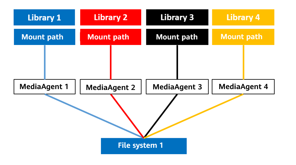
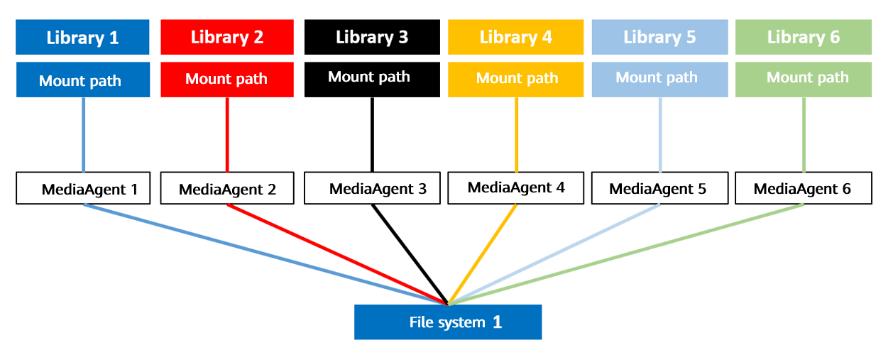
- One-to-many solution (one file system to multiple MediaAgents)
This solution is used in the chapter « Configuration Example ». You can use one file system to maximize the performance of a storage system. In this solution, the application type must be Reduction_Global_Mode or Performance_Global_Mode for file systems.
Only one file system is mounted to all MediaAgents and the mount point on each MediaAgent is created as a mount path of a library.
The following figure shows an example when there are four MediaAgents.
Figure 3-9 Example of the many-to-one solution for library planning
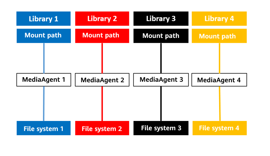
2. One-to-one solution (one file system to one MediaAgent)
One or more file systems are used. One file system is mounted to one MediaAgent and the mount point is created as a mount path of a library.
The following figure shows an example when there are four MediaAgents.
Figure 3-10 Example of the one-to-one solution for library planning
3. GridStor solution
Each file system is mounted to all MediaAgents. The mount directory of one MediaAgent is created as the mount path of a library. The Share Mount Path operation is performed on the mount path to share the mount directories of the same file system on other MediaAgent hosts to the mount path. For details, see 4.4.5.3 Configuring a Library.
The following figure shows an example when there are four MediaAgents and two libraries to be configured.
Figure 3-11 Example of the GridStor solution for library planning


The best practice planning in this document applies to OceanProtect 1.6.0 and 1.7.0 delivery scenarios. For upgrade scenarios, contact R&D engineers for evaluation.
Commvault Policy Planning
Create one policy for each library and associate each MediaAgent with two or three policies.
4. Configuration Example
This chapter uses DataTurbo as an example to describe the configuration process and test results of backup and restoration, remote replication, and WORM by integrating OceanProtect X8000 with Commvault 11 SP30 to back up Oracle databases and VMware VMs.
4.2 Hardware and Software Configuration
4.3 Configuration Planning for Commvault Integration
4.4 Commvault Backup and Restore Configuration
4.5 Configuring the Remote Replication Environment
4.6 Configuring the WORM Feature
4.7 (Optional) Configuring Virtual Synthetic Full Backup Using DASH Full
4.8 Configuring the Tiering Environment
4.9 Best Practice Verification Examples
4.1 Solution Networking
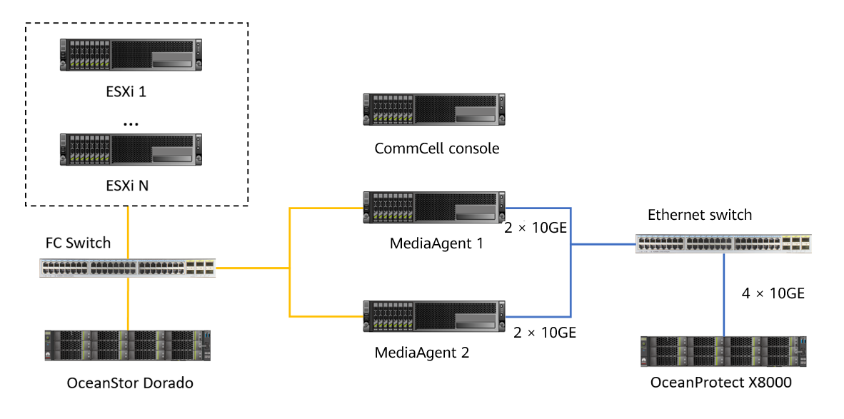
Figure 4-1 shows the networking of the Oracle database and VMware backup solution in this practice.
Figure 4-1 Networking diagram of the OceanProtect X8000 and Commvault solution for backing up Oracle and VMware data

The networking diagram shown in Figure 4-1 is for reference only. For details about the cable connections between the OceanProtect X8000 controller enclosures and application servers, disk enclosures, or other controller enclosures, see « Cabinet Layout and Connection Planning » in the OceanProtect X6000, X8000 Backup Storage 1.x & V200R001 Hardware Installation Guide.
Solution networking for backing up Oracle and VMware data using Commvault:
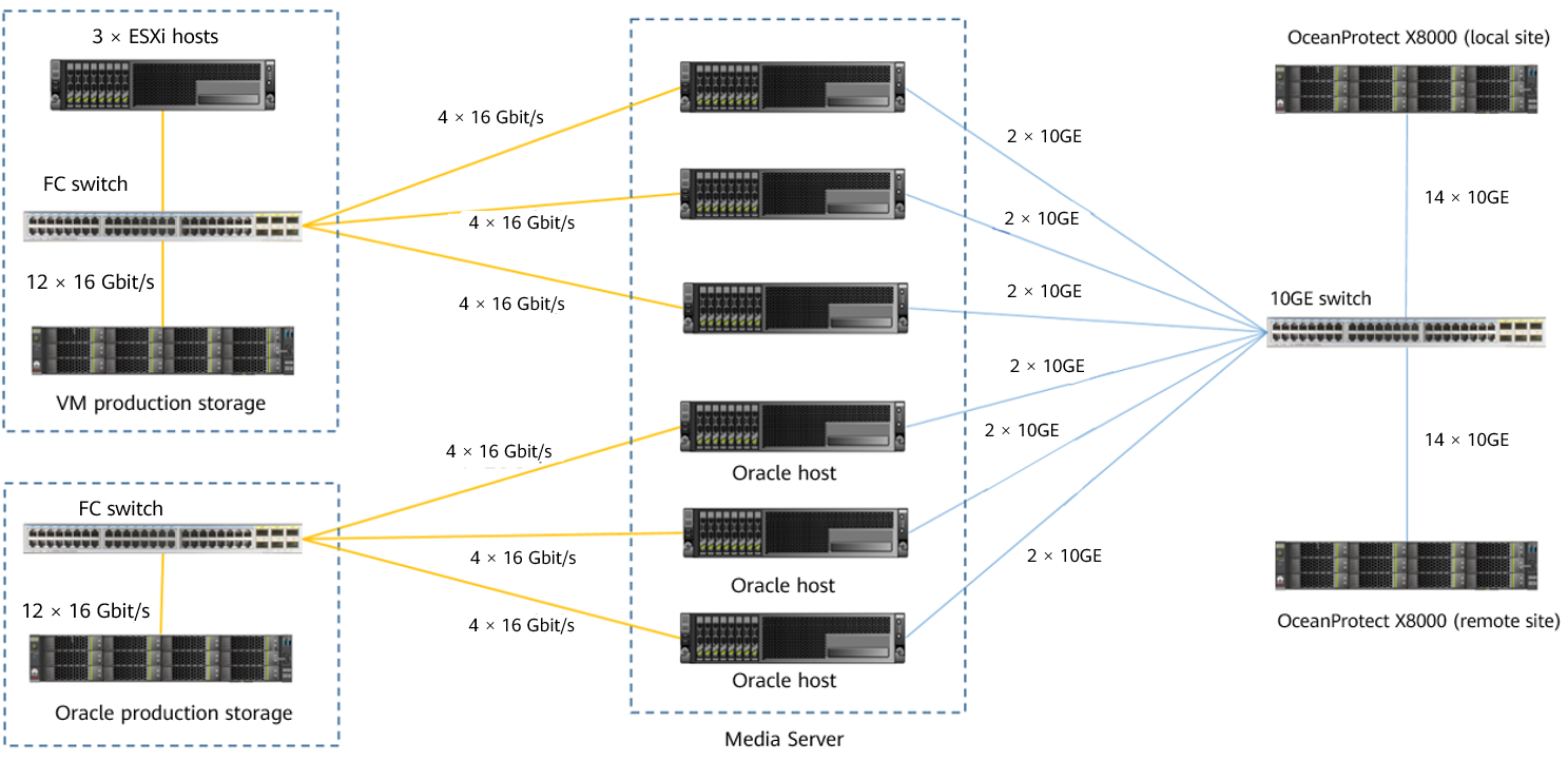
- Oracle: In this practice, three Oracle physical hosts are co-deployed with MediaAgents and are connected to one set of production storage OceanStor Dorado 8000 V6.
- Oracle hosts are connected to the production storage through FC switches. Each Oracle host uses four 16 Gbit/s FC links. The production storage uses 12 x 16 Gbit/s FC links.
- LUNs are created on the production storage and mounted to Oracle hosts through the FC protocol. They are used as volumes for storing Oracle data files and archive logs.
- A Commvault MediaAgent is installed on each Oracle host and connected to OceanProtect X8000 by using 2 x 10GE optical fibers through a 10GE switch.
- VMware: In this practice, three ESXi hosts are deployed and are connected to one set of production storage OceanStor Dorado 6000 V6.
- Two file system hosts are used and connected to the production storage through an FC switch.
- The production storage uses 12 × 16 Gbit/s FC links to connect to the FC switch, in which six links are used by controller A and the other six links are used by controller B.
- CommServe: deployed on a VM and is connected to all MediaAgents through the management network.
- Commvault MediaAgent: In this practice, six MediaAgents are deployed.
- Three MediaAgents are co-deployed with Oracle hosts and connected to the Oracle production storage device through an FC switch.
- The three MediaAgents used to back up VMware data are connected to the VMware production storage device by using 4 × 16 Gbit/s FC links through an FC switch.
- Each MediaAgent uses two 10GE ports to connect to the 10GE switch and to establish a connection between the switch and OceanProtect X8000.
- Local OceanProtect X8000: It is connected to the 10GE service switch through 14 x 10GE optical fibers. Each controller is connected to 7 × 10GE optical fibers. The 12 physical ports are used as backup links to connect to backup servers and two physical ports are used as replication links to connect to remote devices.
- Remote OceanProtect X8000: Controllers A and B are separately connected to the 10GE service switch through 14 × 10GE optical fibers, in which 12 physical ports are used as standby restoration links to connect to backup servers and two physical ports are used as replication links to connect to remote devices.
4.2 Hardware and Software Configuration
4.2.1 Hardware Configuration
Table 4-1 Hardware configuration
Name | Description | Quantity | Function |
|---|---|---|---|
ESXi server |
| 3 | Used to create VMs. |
Oracle server |
| 3 | Oracle host where the Oracle 19c database is installed. |
Commvault CommServe |
| 1 | Manages the MediaAgents and Commvault clients. |
Production storage | Huawei OceanStor Dorado 6000 with dual controllers, 25 SSDs (3.84 TB each), and two 4-port FE 16 Gbit/s FC I/O modules | 2 | Stores production service data to be backed up for testing. |
Production storage | Huawei OceanStor Dorado 8000 with four controllers, 86 SSDs (3.84 TB each), and six 4-port FE 16 Gbit/s FC I/O modules | 1 | Stores production service data to be backed up for testing. |
Backup service switch | Huawei CE6850 | 4 | 10GE switch on the backup service plane |
FC switch | Huawei SNS2248 | 2 | A 16 Gbit/s FC switch used to connect an Oracle host, a file system, and production storage. |
Table 4-2 High-configuration backup media server
Name | Description | Quantity | Function |
|---|---|---|---|
Commvault MediaAgent |
| 6 | Commvault proxy server which reads and writes backup data and manages Commvault storage media |
Table 4-3 Standard-configuration backup media server
Name | Description | Quantity | Function |
|---|---|---|---|
Commvault MediaAgent |
| 4 | Commvault proxy server which reads and writes backup data and manages Commvault storage media |
4.4.2 OceanProtect X8000 (All-Flash) Configuration
Table 4-4 OceanProtect X8000 (all-flash) configuration
Name | Description | Quantity |
|---|---|---|
OceanProtect engine | Huawei OceanProtect X8000 with two controllers | 2 |
10GE front-end interface module | Four 10 Gbit/s SmartIO interface modules | 8 |
SAS SSD | Huawei 7.68 TB SAS SSD | 25 |
4.2.3 Test Software and Tools
Table 4-3 Software description
Software Name | Description |
|---|---|
OceanStor DataTurbo 1.5.0 | The SourceDedupe client is deployed on the backup server to perform source deduplication and compression on backup data, reducing the amount of physical data transmitted from the backup server to the storage and improving the overall bandwidth capability of backup services. |
Commvault 11 SP26 and Commvault 11 SP30 | Commvault 11 SP30 is used for the newly verified single-MediaAgent performance and full synthesis, and Commvault 11 SP26 is used for the rest. |
Oracle 19C | Oracle database |
ESXi 8.0 | Enterprise-level hypervisor developed by VMware, which is used to provide hardware virtualization services |
CentOS 7.6 | CentOS Linux open-source operating system |
SwingBench 2.6 | Third-party tool for generating Oracle test data |
Vdbench | Third-party tool for generating VMware and file backup test data |
SSH client software | SSH terminal connection tool |
4.3 Configuration Planning for Commvault Integration
Commvault backup solution planning:
- Storage pool on OceanProtect X8000: Create a storage pool, configure 25 SAS SSDs (7.68 TB each), and set the RAID policy to RAID 6.
- File system on OceanProtect X8000: One file system is planned to be configured, and the file system capacity is planned to be 200 TB.
- Logical ports of OceanProtect X8000: OceanProtect X8000 is connected to six front-end Commvault MediaAgents by using twelve 10GE physical links. Each physical port is configured with one logical port.
- Commvault library planning
- Repeatedly mount the file system in OceanProtect to the six MediaAgents and configure six libraries on Commvault.
Figure 4-2 Diagram of mounted file systems
- Commvault policy: Configure six policies, where each policy corresponds to one library and one MediaAgent.

Networking principles:
- Scenarios where Commvault uses GridStors: It is recommended that the same type of applications should correspond to one GridStor; one GridStor should correspond to a file system; in a GridStor, one mount path should correspond to the file system mount directory on a backup media server.
- Scenarios where Commvault does not use GridStors: It is recommended that the same type of applications should correspond to one library; one library should correspond to the file system mount directory on a backup media server.
- To maximize performance, all controllers must be used to carry services.
4.4 Commvault Backup and Restore Configuration
4.4.1 Configuration Process
Figure 4-3 NetBackup backup and restore process
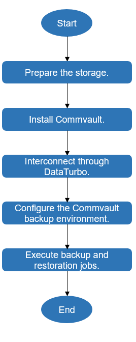
4.4.2 Preparing the Storage
According to the plan in this practice, create one file system and DataTurbo shares on OceanProtect X8000. The configuration procedure is as follows: Create a storage pool, logical ports, file systems, a vStore DataTurbo administrator, and DataTurbo shares.
4.4.2.1 Creating a Storage Pool on OceanProtect X8000
Step 1 On OceanProtect X8000, select 25 disks to create a storage pool and set RAID Policy to RAID 6.
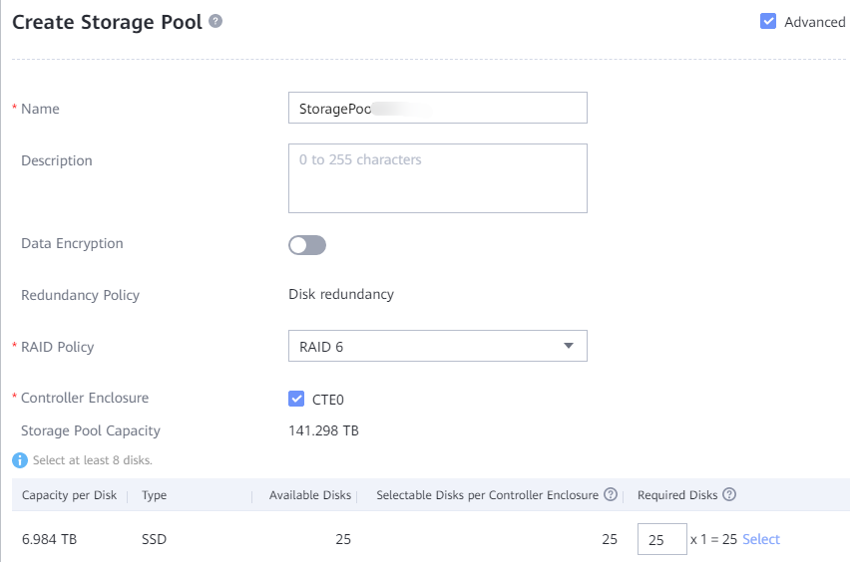
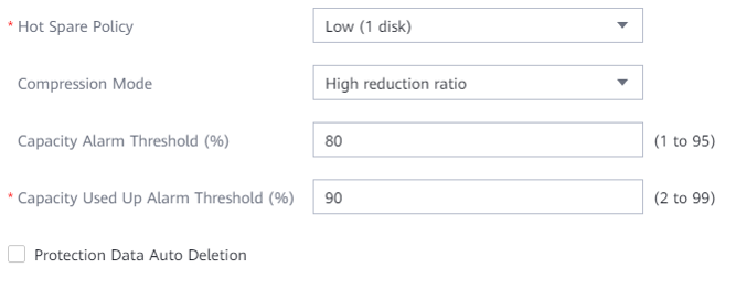
Step 2 Click Advanced, and set Compression Mode, which can be set to High reduction ratio (default) or High performance.
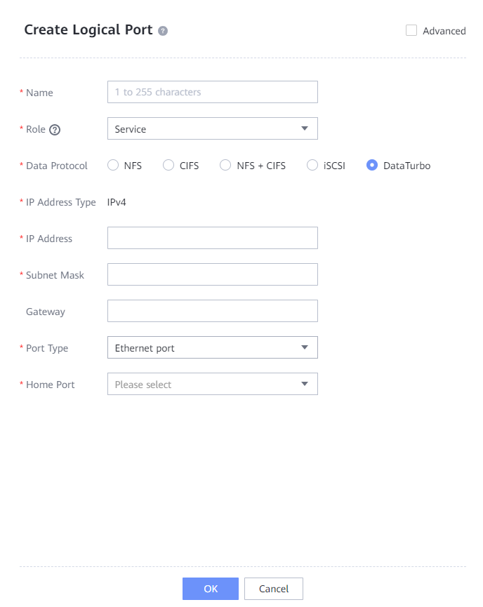
4.4.2.2 Creating Logical Ports on OceanProtect X8000
In this practice, OceanProtect X8000 has 12 physical ports for backup, and each physical port is configured with a logical port. Therefore, create a total of 12 logical ports and set the data protocol to DataTurbo.
The following figure shows a configuration example.
4.4.2.3 Creating File Systems and Shares
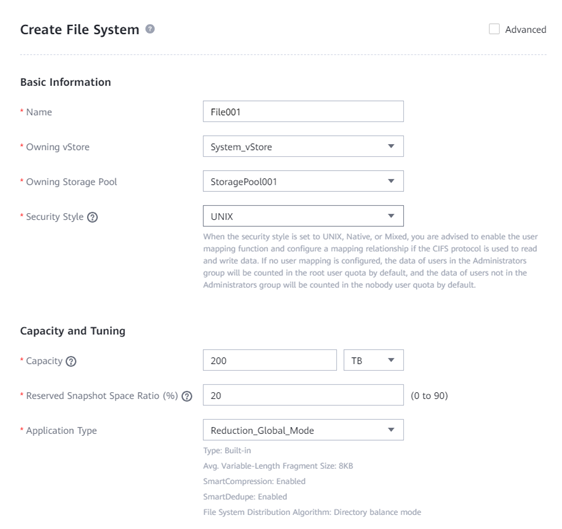
Step 1 Create a file system, select the created storage pool, and set the capacity to 200 TB.
Step 2 If Application Type is set to Reduction_Global_Mode, the high reduction ratio mode is used for the compression mode to save storage resources. If Application Type is set to Performance_Global_Mode, the high performance mode is used for the compression mode.
The following figure shows a file system configuration example.
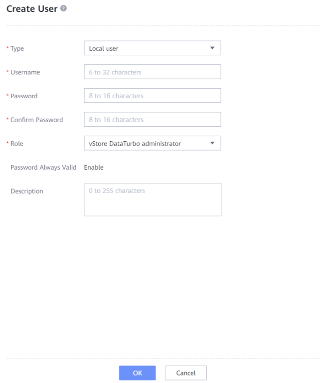
Step 3 Choose Services > vStores > System_vStore > User Management, click Create, set Role to vStore DataTurbo administrator, enter the username in the Username text box, enter the password in the Password and Confirm Password text boxes, and click OK.
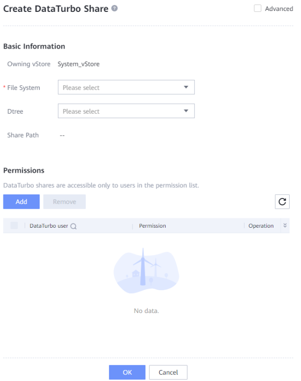
Step 4 Choose Services > Shares > DataTurbo Shares > Create, select the file system for which you want to create a share, click Add, and select the vStore DataTurbo administrator created in Step 3.
—-End
4.4.3 Installing Commvault
In this backup solution, Commvault 11 SP 30 is used. The corresponding Commvault software must be installed on Commvault CommServe and Commvault MediaAgents. For details about the installation process of the Commvault software, see the official documentation.
4.4.4 Integration Through DataTurbo
In this solution, the DataTurbo protocol is used for integration with a backup host. For details, see the OceanProtect Backup Storage 1.6.0-1.7.0 & V200R001 SourceDedupe User Guide.
4.4.4.1 Installation and Deployment
OceanStor DataTurbo must be installed on all MediaAgents. For details, see « Installing, Upgrading, and Uninstalling the DataTurbo Client » in the OceanProtect Backup Storage 1.6.0-1.7.0 & V200R001 SourceDedupe User Guide. During the installation, set the performance level to high.
4.4.4.2 Configuring Source Deduplication
The DataTurbo configuration includes establishing connections and mounting file systems.
- Establishing connections
Separately connect the two ports on each backup host to one logical port on controller A and one logical port on controller B of OceanProtect X8000. That is, connect each backup host to the back-end storage through two 10GE links.
- Mounting file systems
Each backup host uses DataTurbo to mount the file system.
Establishing Connections
Step 1 Run the dataturbo create storage_object storage_name=name ip_list=IP command (name indicates the user-defined storage name and IP indicates the logical port IP address created in 4.4.2.2 Creating Logical Ports on OceanProtect X8000) to establish a connection between OceanStor DataTurbo and the backup storage system. Enter the DataTurbo username and password set in 4.4.2.3 Creating File Systems and Shares as prompted.
In the following example, the storage name is storage1 and the logical port IP address is 10.10.10.10.
[root@host192 mnt]# dataturbo create storage_object storage_name=storage1 ip_list=10.10.10.10
Please input username:
dataturbo_user
Please input password:
**********
Create storage object successfully.
Step 2 Run the dataturbo show storage_object command to check whether the connection is established successfully.
If the following information is displayed in the command output and Status is Normal, the connection is established successfully.
[root@host192 mnt]# dataturbo show storage_object
Storage Name: huawei
User : dataturbo_user
Ips : 10.10.10.10
IpPair :
ID Local Address Remote Address Status
—————————————————————
1 10.10.10.101 10.10.10.10 Normal
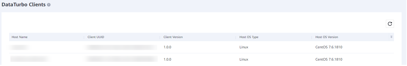
Step 3 After the connection is established, log in to DeviceManager and choose Services > DataTurbo Clients to view the backup server information.
—-End
Mounting File Systems
Step 1 Run the dataturbo mount storage_object storage_name=name filesystem_name=/fsname mount_dir=/mnt/test command to mount a file system created on the backup storage to a specified mount point.
name indicates the storage name defined in Establishing Connections. fsname indicates the name of the file system created in 4.4.2.3 Creating File Systems and Shares.
In the following example, the storage name is storage1, the file system name is testfile, and the mount point is /mnt/test.
[root@host192 mnt]# dataturbo mount storage_object storage_name=storage1 filesystem_name=/testfile mount_dir=/mnt/test
Command executed successfully.
Step 2 Run the df -h command to check whether the mounting is successful.
Filesystem Size Used Avail Use% Mounted on
/dev/mapper/centos-root 45G 24G 21G 55% /
devtmpfs 4.8G 0 4.8G 0% /dev
tmpfs 4.9G 8.0K 4.9G 1% /dev/shm
tmpfs 4.9G 9.3M 4.8G 1% /run
tmpfs 4.9G 0 4.9G 0% /sys/fs/cgroup
/dev/sda1 1014M 179M 836M 18% /boot
tmpfs 984M 0 984M 0% /run/user/0
/testfile 80G 0 80G 0% /mnt/test
—-End
4.4.5 Configuring the Commvault Backup Environment
4.4.5.1 Starting the Commvault Commcell Console
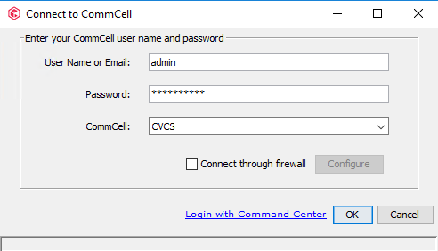
Open the CommCell console, enter the user name and password, and click OK.
4.4.5.2 Configuring Oracle Hosts on CommServe
Configure all Commvault-related hosts, including Oracle hosts and MediaAgents, on CommServe.
Procedure
Step 1 On the Client Computers page, right-click File System under the Oracle host, choose All Tasks from the shortcut menu, and click Reconfigure.

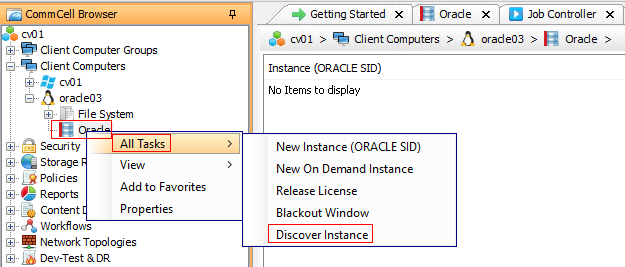
Step 2 Right-click Oracle under the Oracle host, choose All Tasks from the shortcut menu, and click Discover Instance. Then, Commvault can discover the existing instances on the Oracle host.
4.4.5.3 Configuring a Library
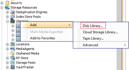
Step 1 In the Storage Resources window, right-click Libraries and choose Add > Disk Library from the shortcut menu.
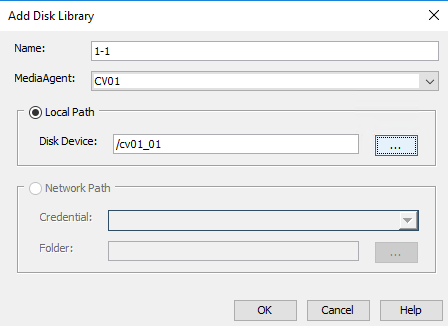
Step 2 On the Add Disk Library page, enter the library name, select the MediaAgent corresponding to the library, select Local Path, and click … to select a directory.
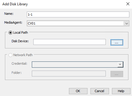
Step 3 Select the path on the MediaAgent to which OceanProtect X8000 is mounted and click OK.

Step 4 Click OK. The library configuration is complete.
Step 5 (Optional) Perform this step when the Figure 3-11 is used.
Select the created mount path and click Share Mount Path.
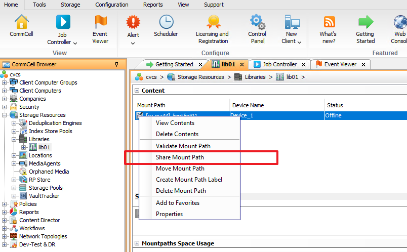
Click Share.

Select the host to be used and select the mount directory of the same file system on the host in Local Path.
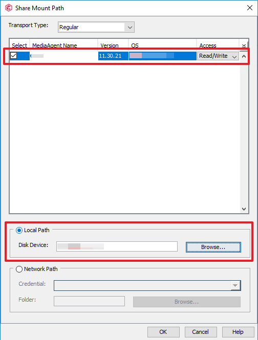
Save the modification of the mount path.
Step 6 Repeat Step 1 to Step 5 to create multiple libraries as planned.
—-End
4.4.5.4 Configuring Storage Pools
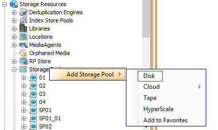
Step 1 On the Storage Resources window, right-click Storage Pools and choose Add Storage Pool > Disk from the shortcut menu.
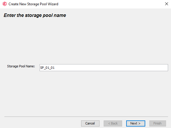
Step 2 Set Storage Pool Name and click Next.
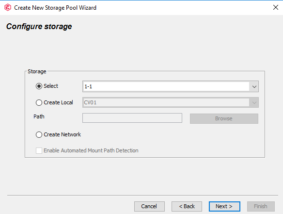
Step 3 In the Storage area, select the library created and click Next.
Step 4 Deselect Enable Deduplication to disable deduplication and click Next.

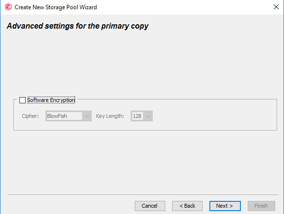
Step 5 By default, Software Encryption is deselected. Click Next.
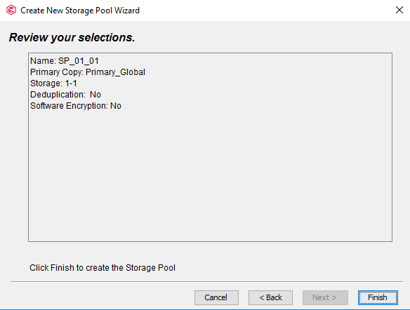
Step 6 Click Finish. The storage pool configuration is complete.
4.4.5.5 Configuring Storage Policies
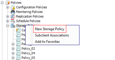
Step 1 On the Policies window, right-click Storage Policies and choose New Storage Policy from the shortcut menu.
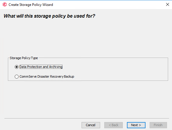
Step 2 Retain the default value Data Protection and Archiving and click Next.
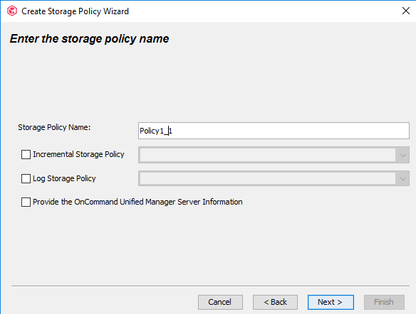
Step 3 Enter a policy name, deselect other options by default, and click Next.
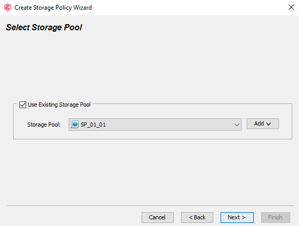
Step 4 Select Use Existing Storage Pool, select a storage pool from the drop-down list, and click Next.
Step 5 Configure streams. Retain the default value 100 in Number of Device Streams and click Next.

Step 6 Confirm the configuration of the policy and click Finish.

—-End
4.4.5.6 Configuring an Oracle Instance on Commvault
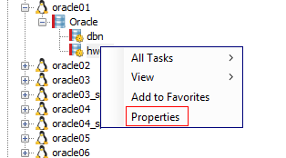
Step 1 On the Client Computers page, select the Oracle host to be backed up, click Oracle, right-click the discovered instance, and choose Properties from the shortcut menu.
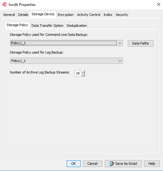
Step 2 Choose Storage Device > Storage Policy, configure the storage policy for the backup of data files and log files, and change the value of Number of Archive Log Backup Streams to 16, that is, the number of archive log backup channels in the Recovery Manager (RMAN) tool.
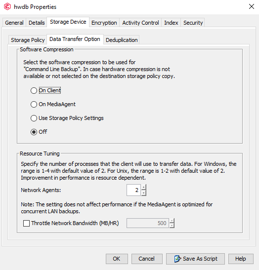
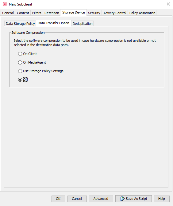
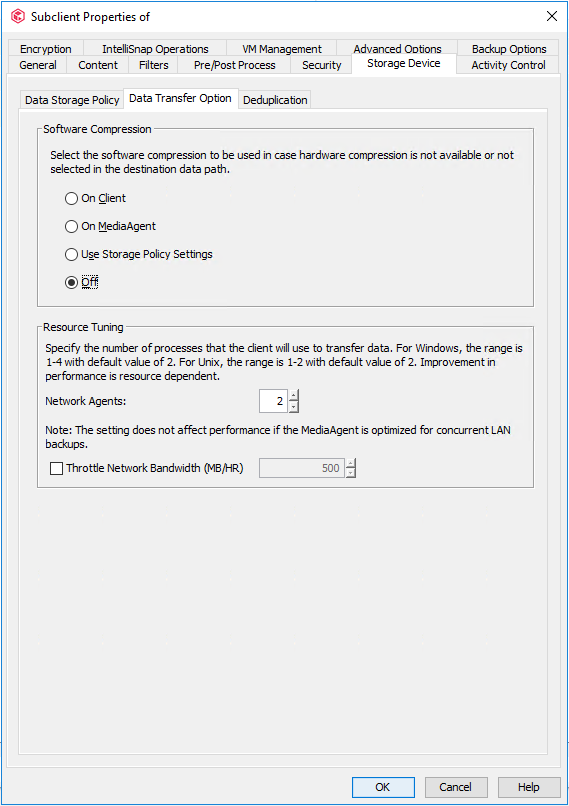
Step 3 Click the Data Transfer Option tab and set Software Compression to Off.
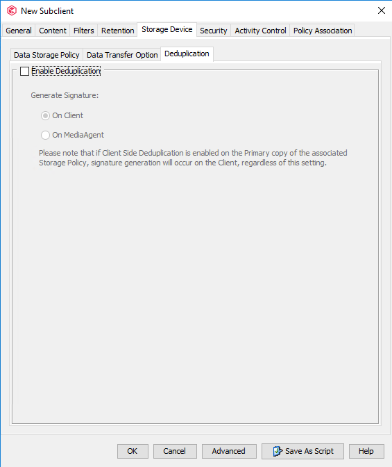
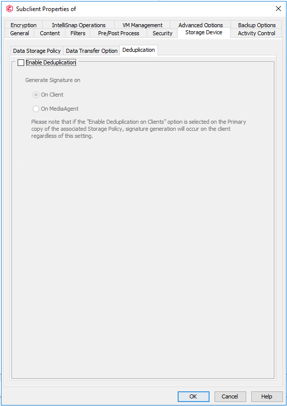
Step 4 Click the Deduplication tab and deselect Enable Deduplication.

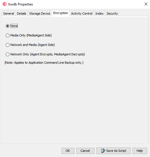
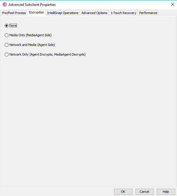
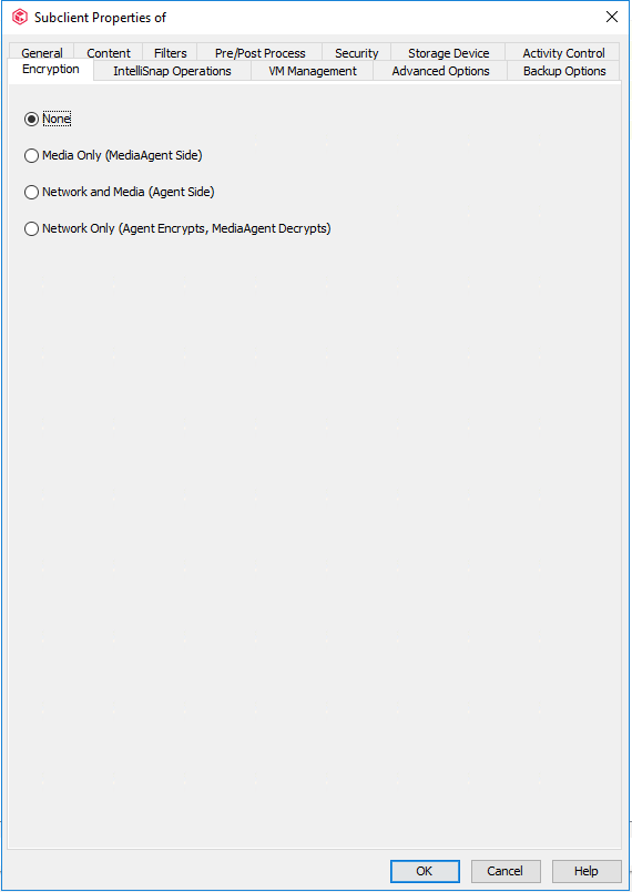
Step 5 Click the Encryption tab and select None.
Step 6 Click OK. The Oracle instance configuration is complete.
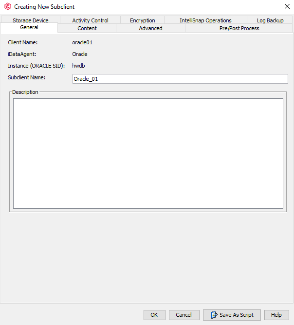
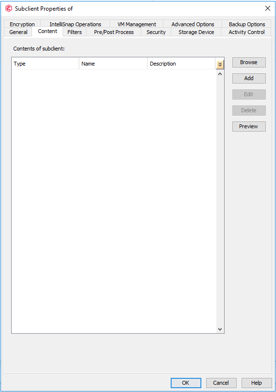
4.4.5.7 Configuring a Subclient for an Oracle Database
You need to create a subclient for each Oracle host to back up Oracle database instances.
Procedure
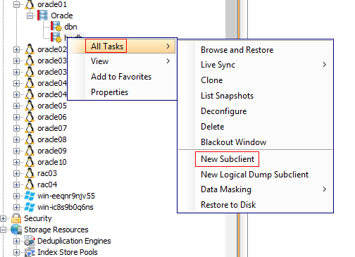
Step 1 On the Client Computers page, select the Oracle host for backup, click Oracle, right-click the discovered instance, and choose All Tasks > New Subclient.
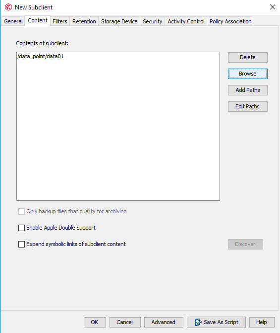
Step 2 On the General tab page, enter a subclient name.
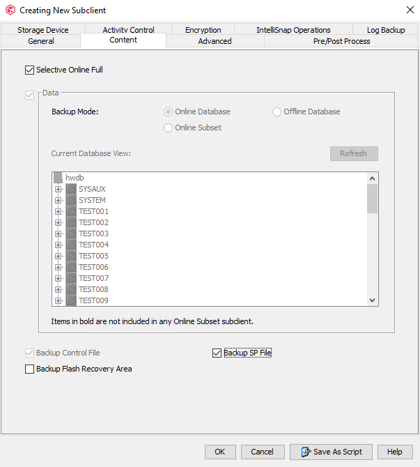
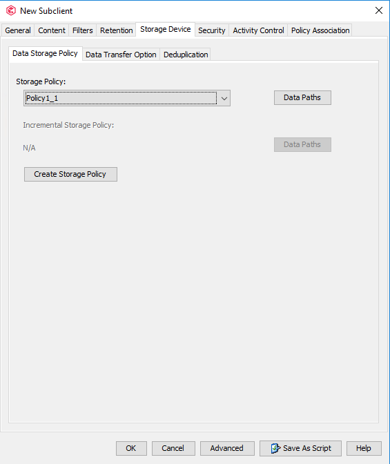
Step 3 Click the Content tab, select the data source to be backed up, and select Selective Online Full and Backup SP File.
Step 4 Click the Storage Device tab. On the Data Storage Policy tab page, select the policy to be used by the subclient and set Number of Data Backup Streams to 16. This parameter is the number of data file backup channels in the RMAN tool, which can be adjusted based on actual conditions.
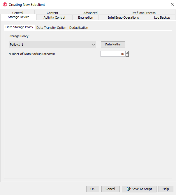
Step 5 Click the Data Transfer Option tab and set Software Compression to Off.

Step 6 Click the Deduplication tab and deselect Enable Deduplication.
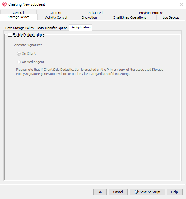
Step 7 Click the Encryption tab and select None.
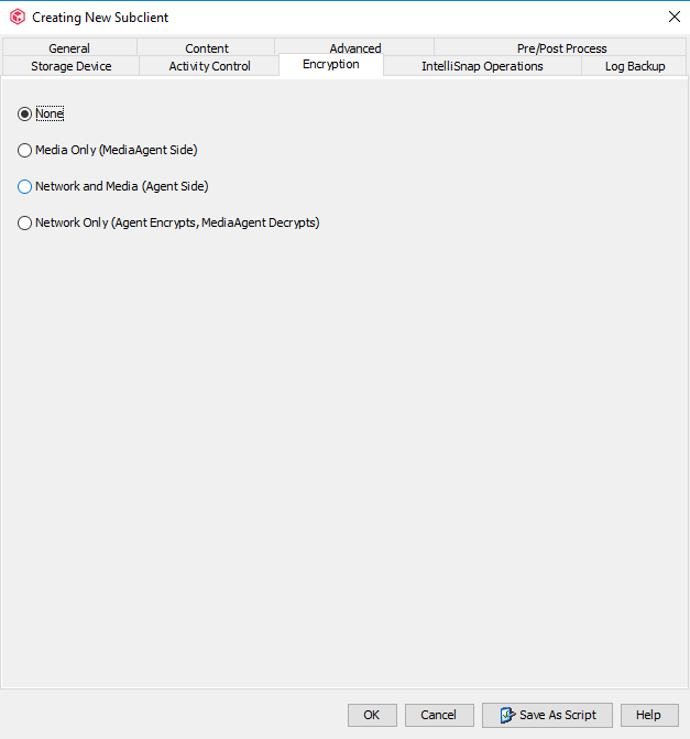
Step 8 Click OK. The subclient configuration of the Oracle database is complete.
4.4.5.8 Configuring a File System Subclient
You can perform the following steps to back up the file system host.
Procedure
Step 1 Expand the file system host to the defaultBackupSet level, and choose All Tasks > New Subclient, and create a file system subclient.

Step 2 On the General tab page, enter a subclient name.

Step 3 Click the Content tab, select the data source to be backed up, click Browse, and select the directory for backup.
Step 4 On the Storage Device tab page, click the Data Storage Policy tab, and select the policy to be used by the subclient.
Step 5 Click the Data Transfer Option tab and set Software Compression to Off.
Step 6 Click the Deduplication tab, deselect Enable Deduplication to disable the deduplication function of the subclient, and click Advanced to configure advanced options.
Step 7 Click the Encryption tab and select None.
Step 8 Click the Performance tab and set the value of Number of Data Readers to Use 15 data readers. That is, change the number of concurrent backup jobs of the subclient to 15.
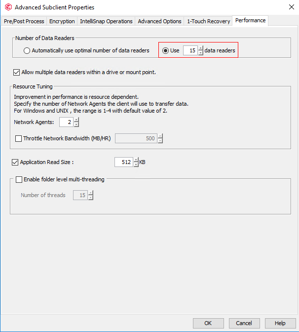
Step 9 Click OK. The subclient configuration of the file system is complete.
4.4.5.9 Configuring VMware on Commvault
Procedure
Step 1 On the Client Computers page, choose New Client > Virtualization > VMware vCenter.
Step 2 In the Create VMware vCenter Client window that is displayed, enter the vCenter IP address in Client Name, and enter the vCenter username and password in User Name and Password, respectively.
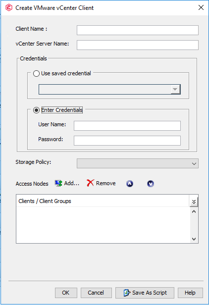
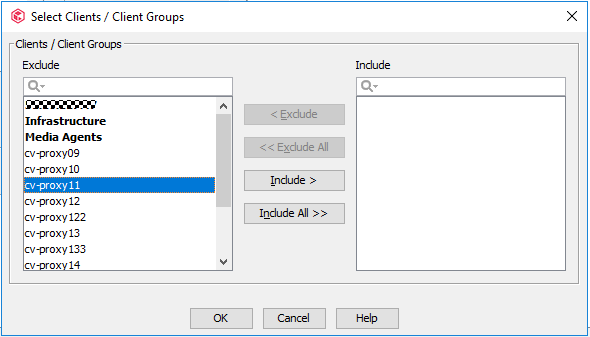
Step 3 Click Add next to Access Nodes. In the Select Clients/Client Groups window that is displayed, select the host where the Virtual Server client component is deployed and click Include. Click OK.
Step 4 On the Create VMware vCenter Client page, click OK.
—-End
4.4.5.10 Configuring a VMware Subclient
Procedure
Step 1 Expand the VMware host to the defaultBackupSet level, choose All Tasks > New Subclient, and create a VMware subclient.
Step 2 On the General tab page, enter a subclient name.
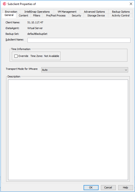
Step 3 Click the Content tab, select the data source to be backed up, click Browse, and select the VM for backup.
Step 4 On the Storage Device tab page, click the Data Storage Policy tab, and select the policy to be used by the subclient.

Step 5 Click the Data Transfer Option tab and set Software Compression to Off.
Step 6 Click the Deduplication tab and deselect Enable Deduplication.
Step 7 Click the Encryption tab and select None.
Step 8 Click the Advanced Options tab and set the value of Number of Data Readers to 16. That is, change the number of concurrent backup jobs of the subclient to 16. Adjust the parameters by referring to the official Commvault documentation based on the project requirements.

Step 9 Click Add. In the Select Clients/Client Groups window that is displayed, select the host where the Virtual Server client component is deployed and click Include. Click OK.

Step 10 Click OK. The VMware subclient configuration is complete.
4.4.6 Performing Backup
Step 1 Expand the Oracle/file system/VMware host, right-click the subclient created, and choose Backup to perform full backup.

Step 2 Select Full in Select Backup Type and Immediate in Job Initiation to perform a full backup immediately.

Step 3 Click OK. The system starts to perform the full backup.
4.4.7 Performing Restoration
4.4.7.1 Configuring Oracle Restoration
This section describes only how to restore Oracle data files and control files to the original locations on the original host (through overwriting). During the actual test, restore the files as required. For details about the restoration procedure, see the Commvault official documentation.

When restoring Oracle control files, start the instance and wait until it enters the nomount state. When restoring Oracle data files, start the instance and wait until it enters the mount state.
Procedure
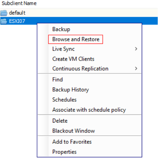
Step 1 Expand the Oracle host to the instance level, right-click the created subclient, and choose Browse and Restore from the shortcut menu.

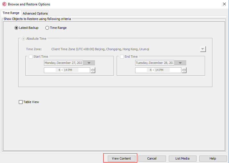
Step 2 On the Browse and Restore Options page, click the Time Range tab, and click View Content to view the data to be restored.

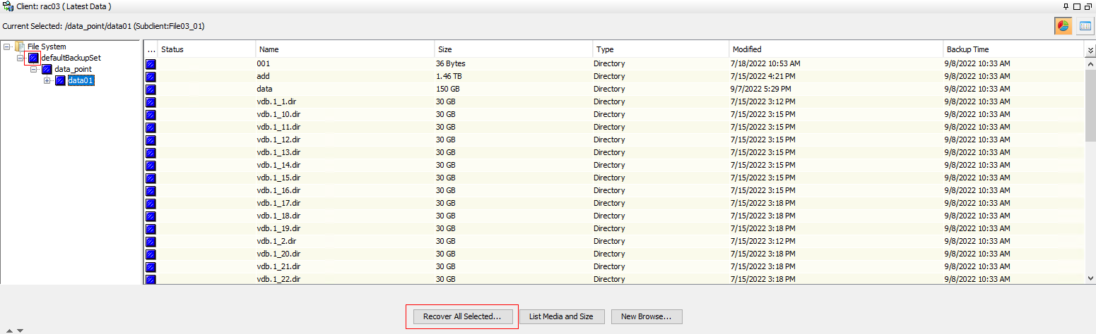
Step 3 Select the data to be restored and click Recover All Selected.
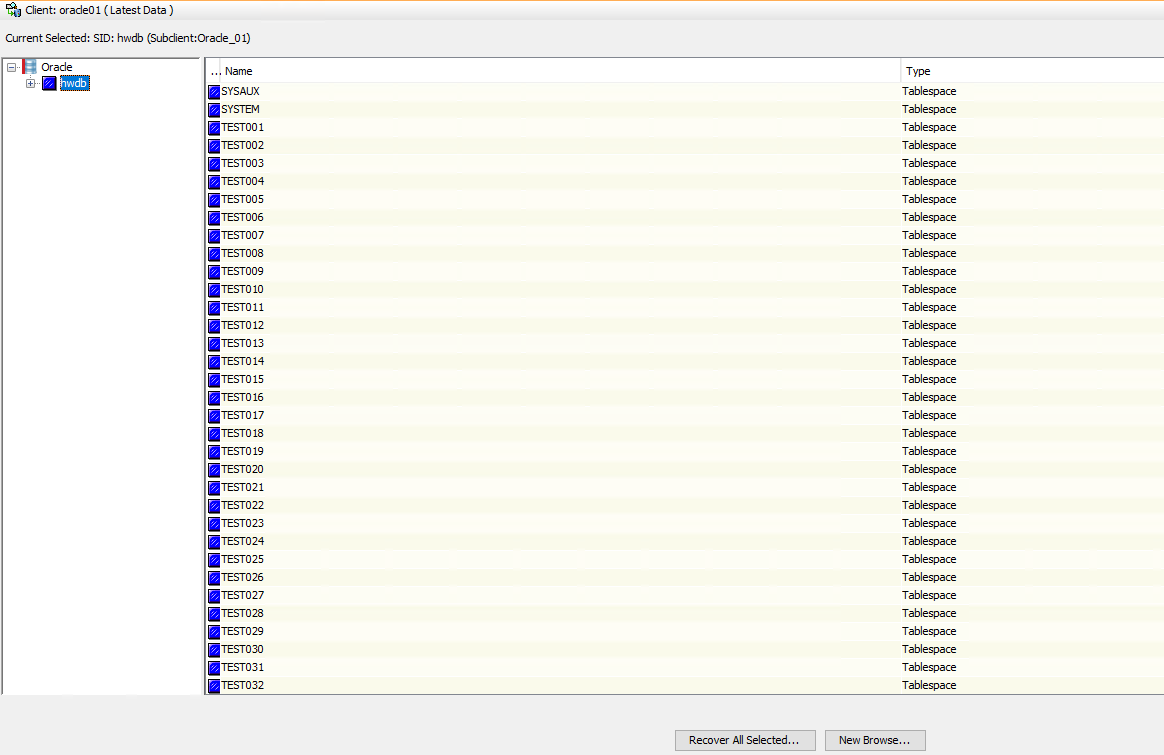
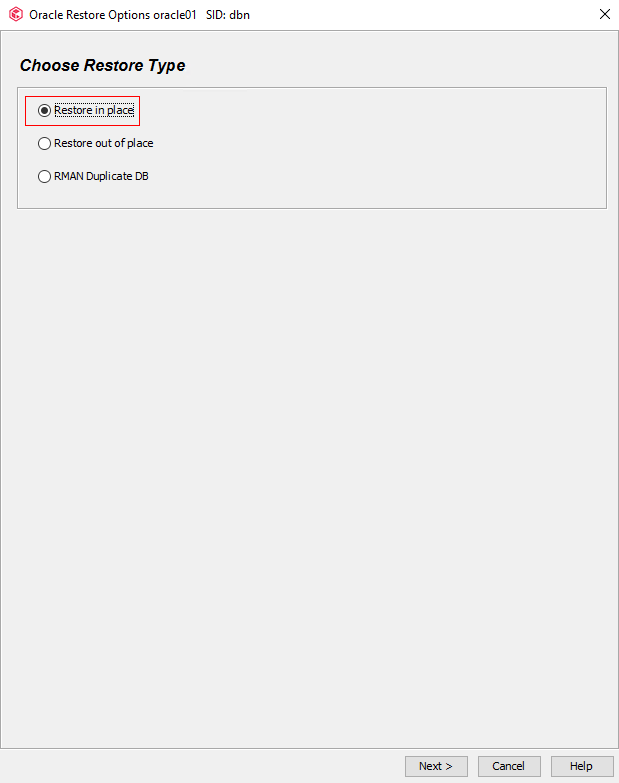
Step 4 On the Choose Restore Type tab page, select Restore in place and click Next.
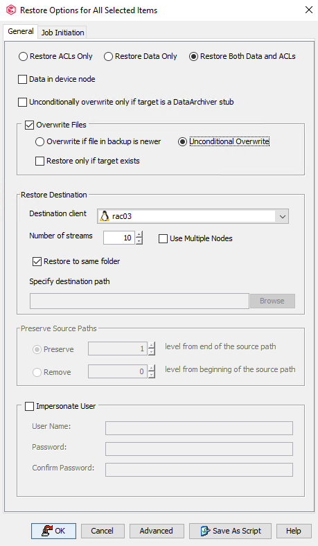
Step 5 On the General tab page, set the value of Number of streams to use for restore to 16. That is, enable 16 channels for restoration. Click Advanced.
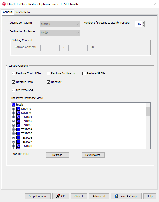
Step 6 On the page that is displayed, click the Options tab, select Switch Database Mode for Restore and Set DBID, and click OK.
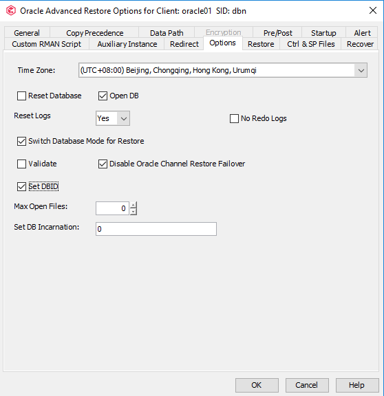
Step 7 Verify that the database status is STARTED. On the General tab page, click OK.

Step 8 In the dialog box that is displayed, click Yes.

—-End

Commvault can restore multiple types of Oracle files, including data files, archive log files, control files, and parameter files. For details, see the Commvault official documentation.
4.4.7.2 Configuring File System Restoration
This section describes only how to restore file systems to the original locations on the original host (through overwriting). During the actual test, restore data as required. For details about the restoration procedure, see the Commvault official documentation.
Procedure
Step 1 Expand the file system host to the defaultBackupSet level, right-click the created subclient, and choose Browse and Restore from the shortcut menu.

Step 2 On the Browse and Restore Options page, click the Time Range tab, and click View Content to view the data to be restored.
Step 3 Select the data to be restored and click Recover All Selected.
Step 4 Select Unconditional Overwrite from the Overwrite Files drop-down list, set the value of Number of Streams, and click OK.
—-End
4.4.7.3 Configuring VMware VM Restoration
This section describes only how to restore VMs to the original locations on the original host (through overwriting). During the actual test, restore data as required. For details about the restoration procedure, see the Commvault official documentation.
Procedure
Step 1 Expand the VMware host to the defaultBackupSet level, right-click the created subclient, and choose Browse and Restore from the shortcut menu.
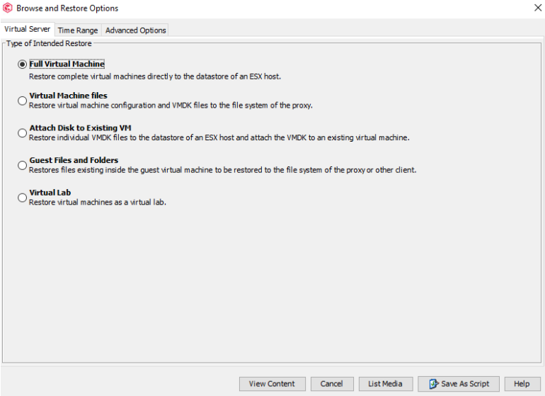
Step 2 On the Virtual Server tab page in the Browse and Restore Options window, select Full Virtual Machine in Type of Intended Restore, and click View Content to view the data to be restored.
Step 3 Select the data to be restored and click Recover All Selected.

Step 4 On the Destination tab page, retain all the default settings and click Next.

Step 5 On the Virtual Machines tab, retain all the default settings and click Next.

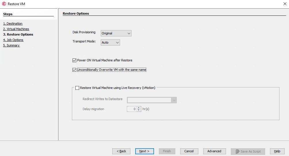
Step 6 On the Restore Options tab page, set Disk Provisioning to Original and Transport Mode to Auto, select Power ON Virtual Machine after Restore and Unconditionally Overwrite VM with the same name, and click Next.
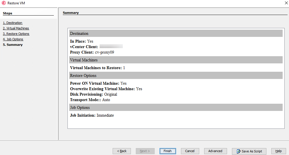
Step 7 On the Job Options tab page, select Immediate under Job Initiation and click Next.

Step 8 Click Finish. The restoration job configuration is complete.
4.5 Configuring the Remote Replication Environment
4.5.1 Configuration Process

This section describes how to configure the OceanProtect Backup Storage. For details about how to integrate the OceanProtect Backup Storage with Commvault and configure backup and restoration, see « Remote Replication Between OceanProtect Backup Storage Systems » in the OceanProtect Backup Storage 1.6.0 Commvault Integration User Guide (Backup Storage Solution).
4.5.2 Configuring Remote Replication
4.5.2.1 Creating Replication Logical Ports
In this practice, OceanProtect X8000 has two physical ports that can be used as replication links. Each physical port is configured with one logical port. A total of two logical ports are created. Use the same method to configure logical ports on the local and remote devices. The following is an example of configuring logical ports:
Step 1 Log in to DeviceManager of the remote device.
Step 2 Choose Services > Network > Logical Ports.
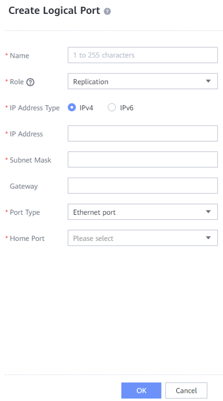
Step 3 Select All vStores for vStore. Click Create. On the Create Logical Port page that is displayed, set Role to Replication and enter key information such as the IP address.
—-End
4.5.2.2 Creating a Remote Device Administrator
Step 1 Log in to DeviceManager of the remote device.
Step 2 Choose Settings > User and Security > Users and Roles > Users.
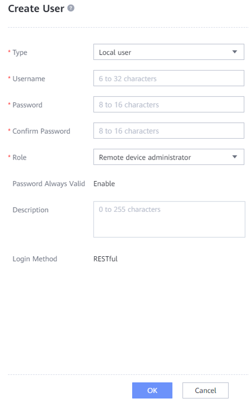
Step 3 Click Create. On the Create User page that is displayed, set Role to Remote device administrator, enter the username and password, and click OK to create a remote device administrator.
The following figure shows a configuration example.
—-End
4.5.2.3 Creating a Remote Device
Step 1 Log in to DeviceManager of the local device.
Step 2 Choose Data Protection > Remote Devices.
Step 3 Click . The Add Remote Device page is displayed.

Set Link Type to IP link, and set Local Port, Remote IP Address, Remote Device Administrator, and Password. Then, click Connect.

—-End
4.5.3 Creating Remote Replication
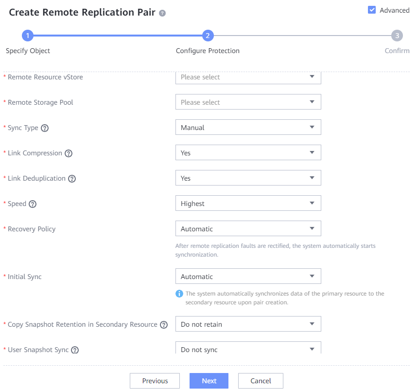
Step 1 Log in to DeviceManager of the local device. Choose Data Protection > Remote Replication > File Systems, and click Create. On the Create Remote Replication Pair page that is displayed, select file systems for which you want to create a remote replication pair, and click Next.

Step 2 On the Configure Protection page, select Advanced, set Link Compression to Yes, Link Deduplication to Yes, and Speed to Highest, and retain the default settings for other options.
4.6 Configuring the WORM Feature
To integrate Commvault with the WORM feature of OceanProtect X8000, you need to make configurations on both Commvault and OceanProtect X8000.
OceanProtect X8000 provides a WORM protection period. The WORM protection period set by Commvault must be within this period. The WORM protection period of backup files is the WORM protection period set by Commvault. If the WORM protection period set by Commvault is less than the minimum WORM protection period provided by OceanProtect X8000, the WORM protection period of backup files is the minimum WORM protection period provided by OceanProtect X8000. Otherwise, if the WORM protection period set by Commvault is greater than the maximum WORM protection period provided by OceanProtect X8000, the WORM protection period of backup files is the maximum WORM protection period provided by OceanProtect X8000.
4.6.1 Configuring the WORM Feature of OceanProtect X8000
You only need to enable the WORM feature on OceanProtect X8000 when configuring the file system. Other configurations are the same as those in 4.4.2 Preparing the Storage.
Set the WORM properties of the file system to be hidden. To display hidden options, click Advanced. The WORM file system ensures that a file enters the protected state after being written. In this case, the file cannot be modified, moved, or deleted, but can be read for multiple times.
Before creating a WORM file system for the first time, you must initialize the WORM regulatory clock. After this parameter is enabled, the global security regulatory clock is initialized to the current system time and time zone.
Set the protection period as required.

4.6.2 Configuring the WORM Feature on Commvault
4.6.2.1 Configurations
You need to start Commvault CommCell Console, configure the client host on CommServe, configure libraries, configure storage pools, and configure storage policies. The operations are the same those from 4.4.5.1 Starting the Commvault Commcell Console to 4.4.5.5 Configuring Storage Policies.
4.6.2.2 Importing an Enable Storage Workflow
Step 1 You need to download an Enable WORM Storage workflow from the Commvault official website.
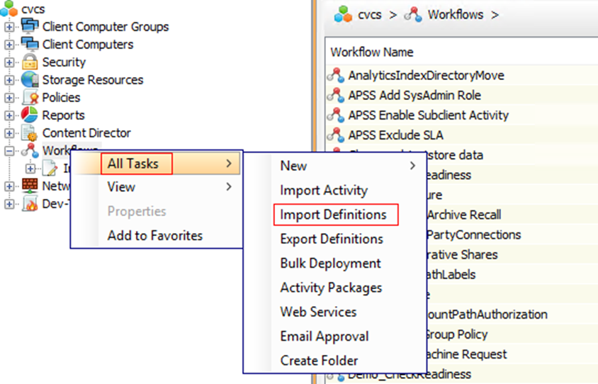
Step 2 Import an Enable WORM Storage workflow to Commvault. Right-click Workflows, choose All Tasks, and click Import Definitions.
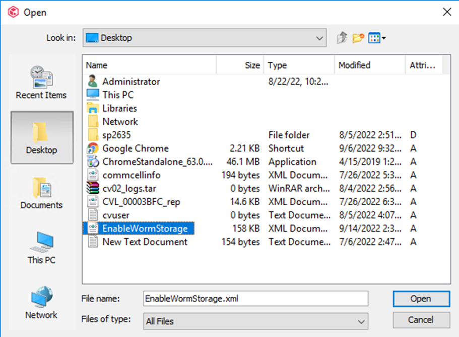
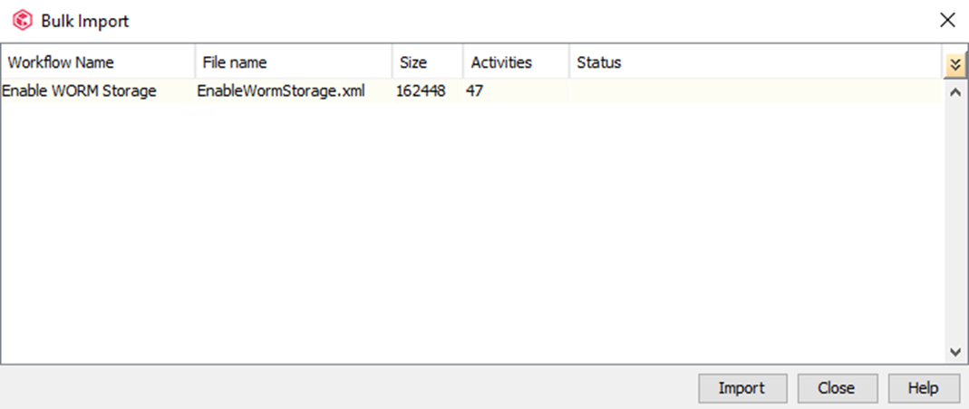
Step 3 Select the downloaded EnableWormStorage file and click Open. On the Bulk Import page, click Import and OK.

—-End
4.6.2.3 Configuring the WORM Storage Workflow
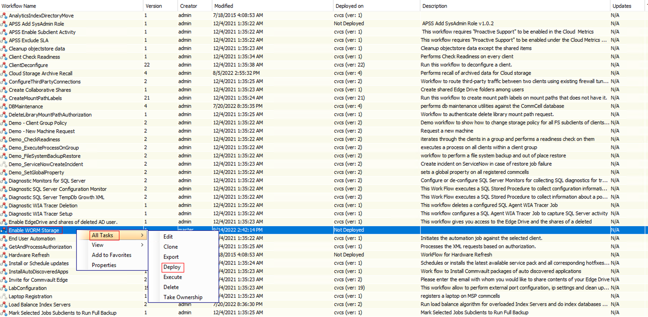
Step 1 On the Workflows page, right-click Enable WORM Storage, choose All Tasks, and click Deploy.
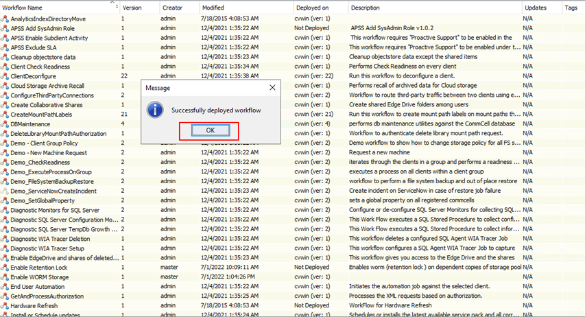
Step 2 Select an engine and click OK. In the message box that is displayed, click OK.

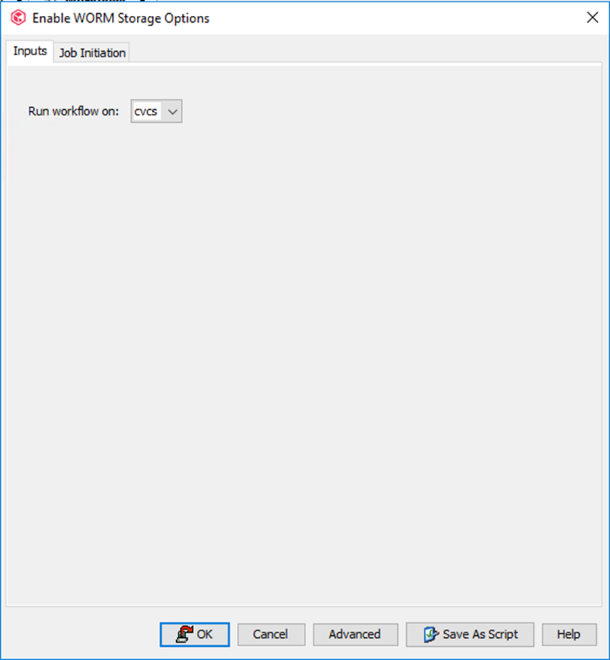
Step 3 Right-click Enable WORM Storage, choose All Tasks, and click Execute.

Step 4 On the Enable WORM Storage Options page, select the host where the workflow is running.
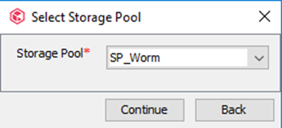
Step 5 On the Select Storage Pool page, select the storage pool for which you want to configure WORM. The WORM Lock period is the copy retention period retained in the Storage Policy.

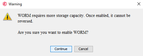
Step 6 In the Warning dialog box, click Continue.
—-End
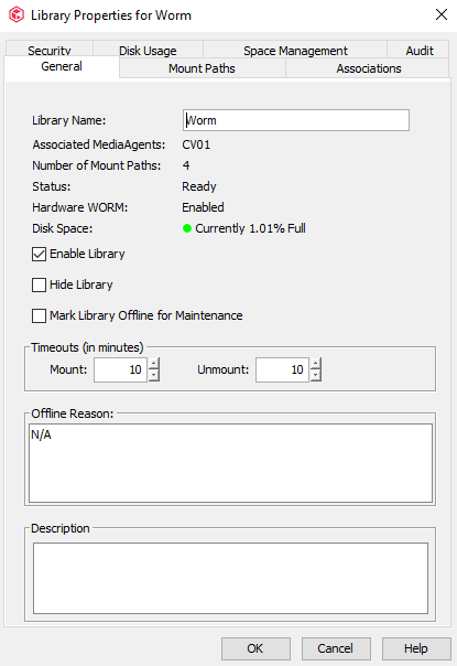
4.6.2.4 Verifying the WORM Storage Workflow
Step 1 Right-click the created library with the WORM feature and verify that Hardware WORM is Enabled.
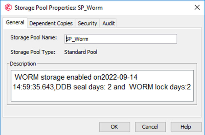
Step 2 Right-click the created storage pool with the WORM feature and check whether WORM storage enabled is displayed in Description.
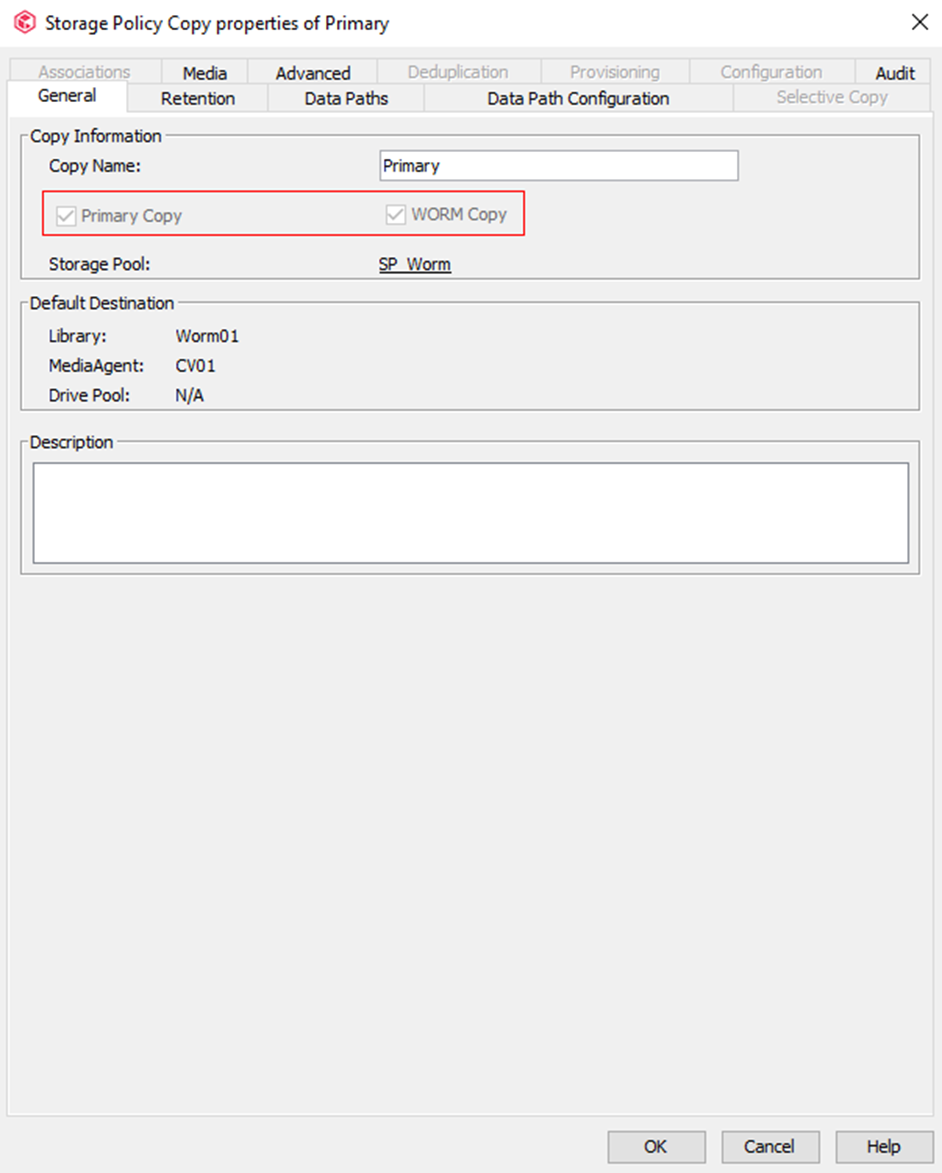
Step 3 Right-click the created storage policy with the WORM feature and ensure that Primary Copy and WORM Copy are selected.
—-End
4.6.2.5 Configuring a Subclient
The procedure for configuring a subclient is the same as that in 4.4.5.7 Configuring a Subclient for an Oracle Database or 4.4.5.8 Configuring a File System Subclient.
4.6.3 Performing Backup
The procedure for executing a backup job is the same as that described in 4.4.6 Performing Backup.
4.6.4 Performing Restoration
The procedure for executing a restoration job is the same as that described in 4.4.7 Performing Restoration.
4.7 (Optional) Configuring Virtual Synthetic Full Backup Using DASH Full
After a full backup and multiple incremental backups are complete, you can perform a synthetic full backup as required.
For a common synthetic full backup, the latest full copy is copied and then incremental data is synthesized.
If you want to use virtual synthetic full backup (only synthesizing backup copy indexes without copying a full copy), you need to use the Commvault DASH Full feature, which takes effect after Commvault deduplication is enabled.
4.7.1 Creating and Mounting Logical Volumes
Select a local SSD of the MediaAgent server to create a logical volume and mount the logical volume to a specified directory on the MediaAgent for the DDB directory in 4.7.3 Configuring Storage Pools.
Step 1 Run the lsblk command on the MediaAgent server to check the status of local disk.
Step 2 Run the pvcreate /dev/xxx command and create /dev/xxx as a physical volume.
Step 3 Run the vgcreate vgname /dev/xxx command to create a logical volume group. In this command, vgname indicates the name of the logical volume group.
Step 4 Run the lvcreate -n vlname -L Gg vgname command to create a logical volume. In this command, vlname indicates the logical volume name, Gg indicates the logical volume size, and vgname indicates the logical volume group name.
Step 5 Run the mkfs.ext4 /dev/vgname/vlname command to format the logical volume. In this command, vlname indicates the logical volume name and vgname indicates the logical volume group name.
Step 6 Run the mount /dev/vgname/vlname /xxx command to mount the logical volume to the execution directory. In this command, vgname indicates the logical volume group name, vlname indicates the logical volume name, and /xxx indicates the specified directory.
—-End
4.7.2 Configuring a Library
For details, see 4.4.5.3 Configuring a Library.
4.7.3 Configuring Storage Pools
Step 1 In the navigation tree on the left, click Storage Resources and right-click Storage Pools.
Step 2 Choose Add Storage Pool > Disk and create a storage pool.
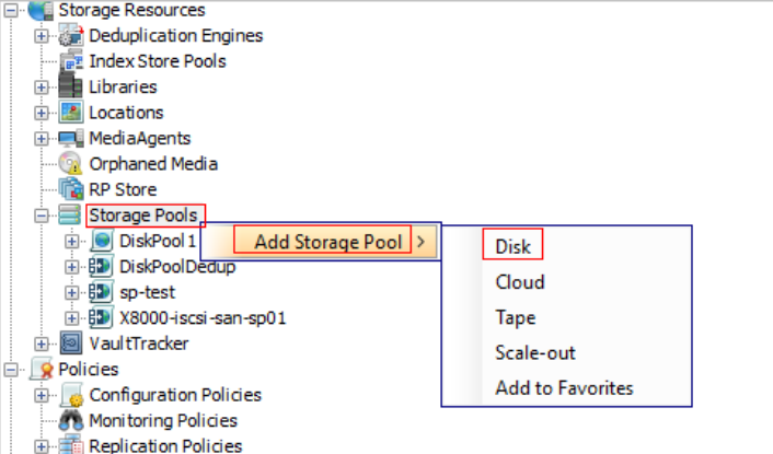
Step 3 In the Enter the storage pool name window, enter a storage pool name and click Next.
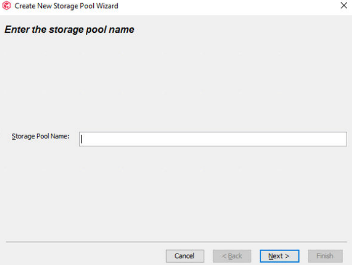
Step 4 In the Configure storage window, select the library for which you want to create a storage pool and click Next.
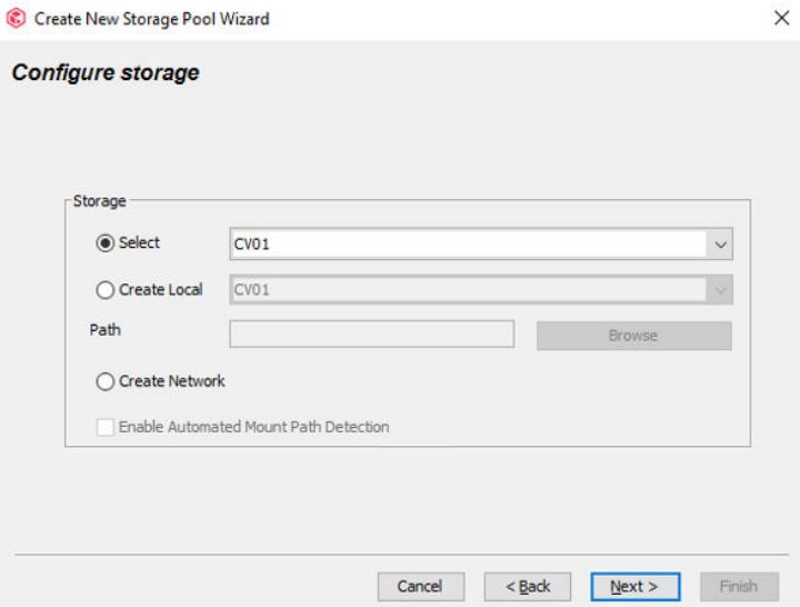
Step 5 Set parameters in the Enable deduplication on Storage pool window.
- Select Enable Deduplication to enable deduplication.
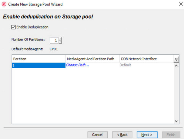
- Set Number Of Partitions.
- Click Choose Path. In the Partition Path dialog box, set MediaAgent.

- In the Partition Path dialog box, click Browse and select the mounted logical volume as the DDB directory. For details about how to create and mount logical volumes, see 4.7.1 Creating and Mounting Logical Volumes.
- Click OK.
- After the configuration in the Enable deduplication on Storage pool window is complete, click Next.
Step 6 In the Advanced settings for the primary copy window, determine whether to perform encryption based on the site requirements (encryption not required in this practice) and click Next.
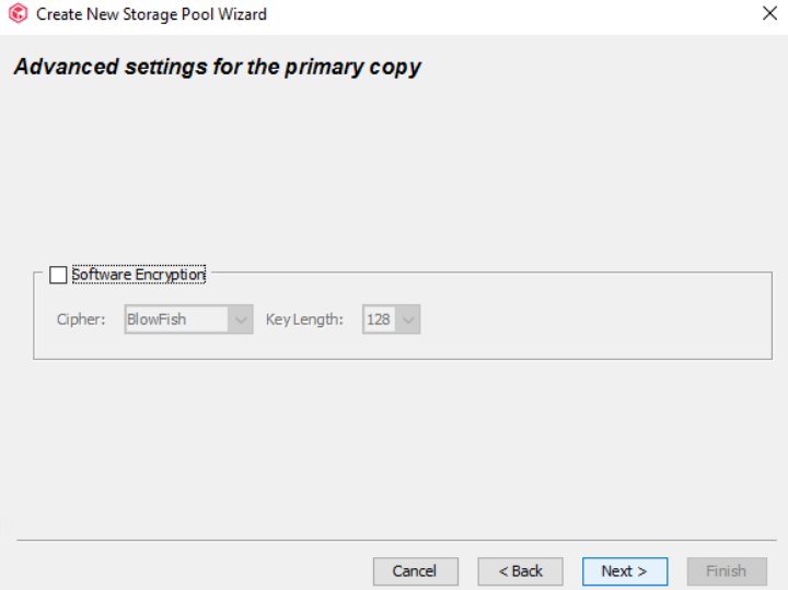
Step 7 In the Review your selections. window, confirm the storage pool configuration and click Finish.
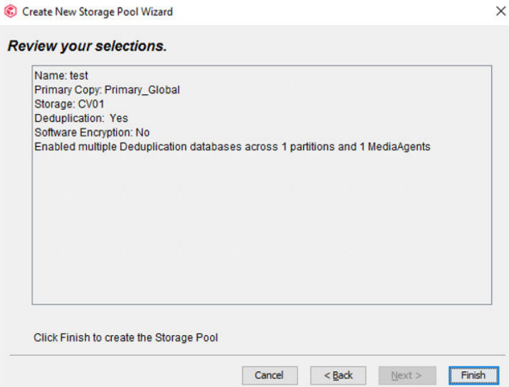
—-End
4.7.4 Configuring Storage Policies
For details about the configuration procedure, see 4.4.5.5 Configuring Storage Policies. Select the storage pool created in 4.7.3 Configuring Storage Pools for Storage Pool.
4.7.5 Configuring a VMware Client
For details, see 4.4.5.9 Configuring VMware on Commvault.
4.7.6 Configuring a Subclient
Step 1 Expand the VMware host to the defaultBackupSet level, choose All Tasks > New Subclient, and create a VMware subclient.
Step 2 On the General tab page, enter a subclient name.
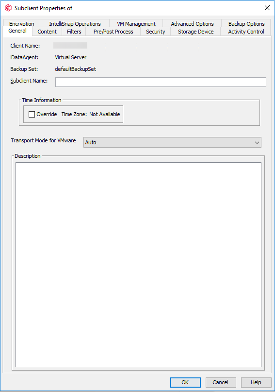
Step 3 Click the Content tab, select the data source to be backed up, click Browse, and select the VM for backup.

Step 4 On the Storage Device tab page, click the Data Storage Policy tab, and select the policy to be used by the subclient.
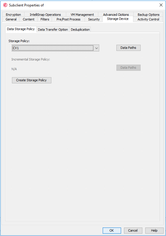
Step 5 Click the Data Transfer Option tab and set Software Compression to Off.

Step 6 Click the Deduplication tab, select Enable Deduplication and On MediaAgent to enable deduplication for subclients.

Step 7 Click the Encryption tab and select None.

Step 8 Click the Advanced Options tab and set the value of Number of Data Readers to 16. That is, change the number of concurrent backup jobs of the subclient to 16.
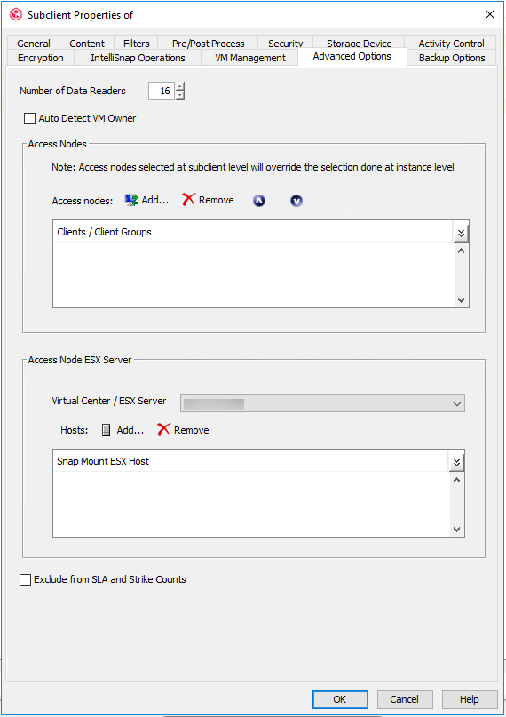
Step 9 Click Add. In the Select Clients/Client Groups window that is displayed, select the host where the Virtual Server client component is deployed and click Include. Click OK.
Step 10 Click OK. The VMware subclient configuration is complete.
—-End
4.7.7 Performing Synthetic Full Backup
After a full backup and multiple incremental backups are complete, you can perform a synthetic full backup for VMs.
Step 1 Right-click the subclient that requires synthetic full backup and choose Backup from the shortcut menu.
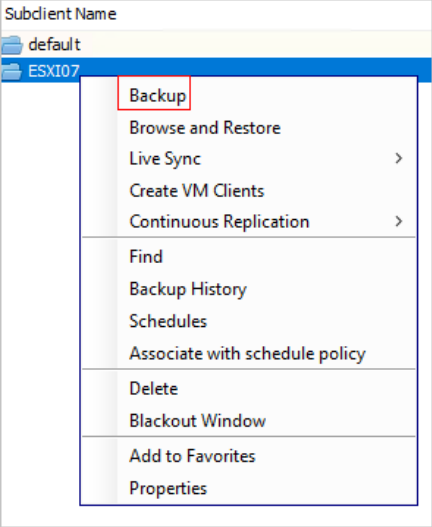
Step 2 On the Backup Options page, set Select Backup Type to Synthetic Full and Job Initiation to Immediate or Schedule based on the site requirements.
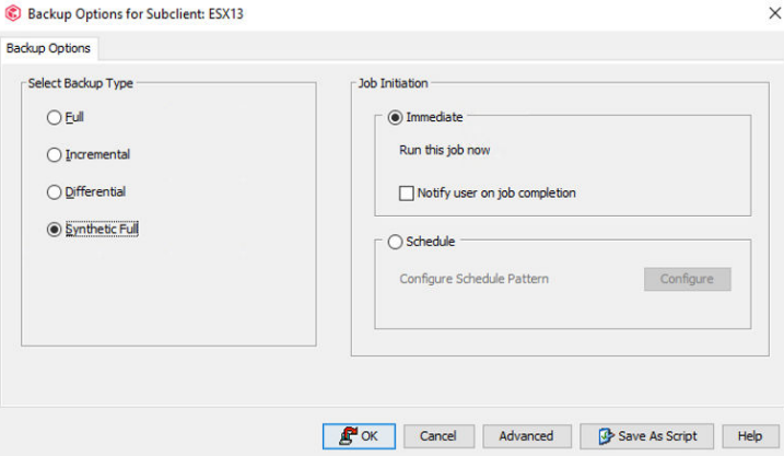
Step 3 Click OK.
4.8 Configuring the Tiering Environment
According to industry regulations or service requirements, customers usually have long-term data retention requirements. To reduce the tiering bandwidth and improve the tiering efficiency, this version provides the enhanced function of archiving deduplicated backup data to the OceanProtect based on the original capability of tiering to the OceanProtect. This feature is supported in OceanProtect 1.7.0.
4.8.1 Environment Networking
- The CommCell Console and MediaAgent form the backup environment. The MediaAgent connects to the ESXi and OceanProtect X8000.
- Logical ports of OceanProtect X8000: Connect to the MediaAgent through two 10GE physical links. Each physical port is configured with one logical port.
- Tiering links: OceanProtect X6000 connects to OceanProtect X8000 through two 10GE physical links. Each physical port is configured with one logical port.
Figure 4-4 Networking example

4.8.2 Configuring SmartMobility
4.8.2.1 Creating a Remote Address Pool
4.8.2.1.1 Creating Remote Logical Ports
In this practice, the remote device OceanProtect X6000 has two physical ports for connection links. Each physical port is configured with one logical port. Two logical ports with the data protocol of NFS + CIFS are created.
Step 1 Log in to DeviceManager of the remote device.
Step 2 Choose Services > Network > Logical Ports.
Step 3 Select All vStores for vStore. Click Create. On the Create Logical Port page that is displayed, set Role to Service and enter key information such as the IP address.
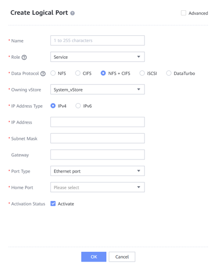
4.8.2.1.2 Creating a Remote Address Pool
Step 1 Log in to DeviceManager of the local device.
Step 2 Choose Services > Resource Tuning > SmartMobility.
Step 3 On the Remote Address Pools tab page, click Create to go to the Create Remote Address Pool dialog box. Set the name of the remote address pool, and enter the IP address of the logical port created in 4.8.2.1.1 Creating Remote Logical Ports in the IP Address text box. To enter multiple IP addresses, click .

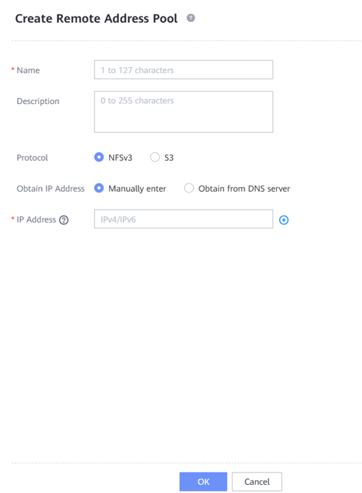
4.8.2.2 Creating a Local IP Address Pool
Step 1 On the local device, choose Services > Resource Tuning > SmartMobility > Local IP Address Pools.
Step 2 Click Create to go to the Create Local IP Address Pool dialog box. Specify the name of the local IP address pool.

Step 3 Click Create Logical Port. In the Create Logical Port dialog box that is displayed, set the name and key information such as the IP address.
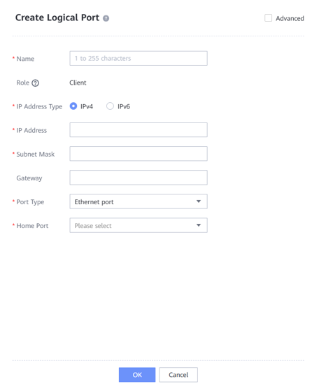
—-End
4.8.2.3 Creating a Remote Device
Step 1 On the local device, choose Services > Resource Tuning > SmartMobility > Remote Devices.
Step 2 Click + to go to the Add Remote Device dialog box. Customize the remote device name. Select the IP address pool created in 4.8.2.2 Creating a Local IP Address Pool for Local IP Address Pool, and select the address pool created in 4.8.2.1.2 Creating a Remote Address Pool for Remote Address Pool. Set NFS Port to 2049 and Mount Port to 2050 for the remote Huawei NAS device. In this example, the remote file system is in NFS share mode. User root is used to access the remote device. Therefore, set both User ID and User Group ID to 0.
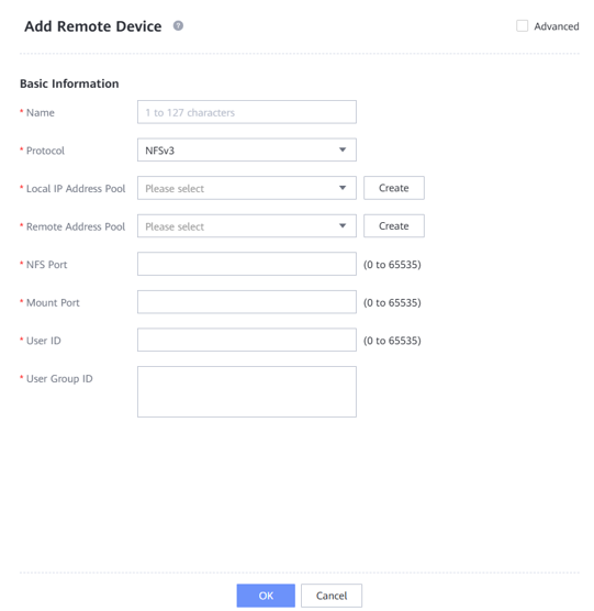
—-End
4.8.2.4 Creating a Policy Template
Step 1 Choose Services > Resource Tuning > SmartMobility > Policy Templates.
Step 2 Click Create. On the Create Policy Template page that is displayed, enter the policy name. In this example, Mode is set to Periodic by default.
Step 3 Set Migration Conditions based on the service requirements. In this example, select By file operation time and set mtime ≥ to 30 days to tier copy files that are not modified within 30 days.
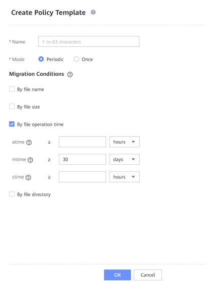
—-End
4.8.2.5 Creating SmartMobility
Step 1 Choose Services > Resource Tuning > SmartMobility > SmartMobility.
Step 2 Select the desired vStore from the vStore drop-down list in the upper left corner.
Step 3 Select the desired file system and click Create. The Create SmartMobility dialog box is displayed.
Step 4 Select a local file system and a remote device for which you want to create a SmartMobility policy.
Step 5 Enter the file share path or bucket name used by the remote device. In this example, NFSv3 is used. Enter the NFS share path of the remote NAS device. Set basic information based on the service requirements. In this example, set Migration Trigger Threshold (%) to 99, enable Migration, set Migration Rate to High, enable Recall upon Read, and set Recall Stop Threshold (%) to 99.
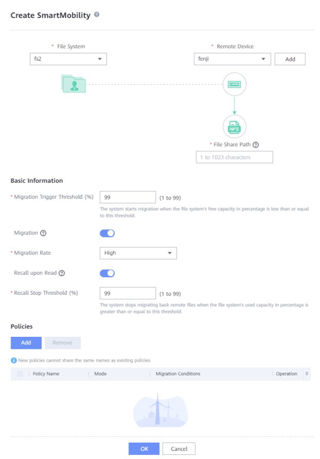
Step 6 Click Add and select the created policy template. Click OK.
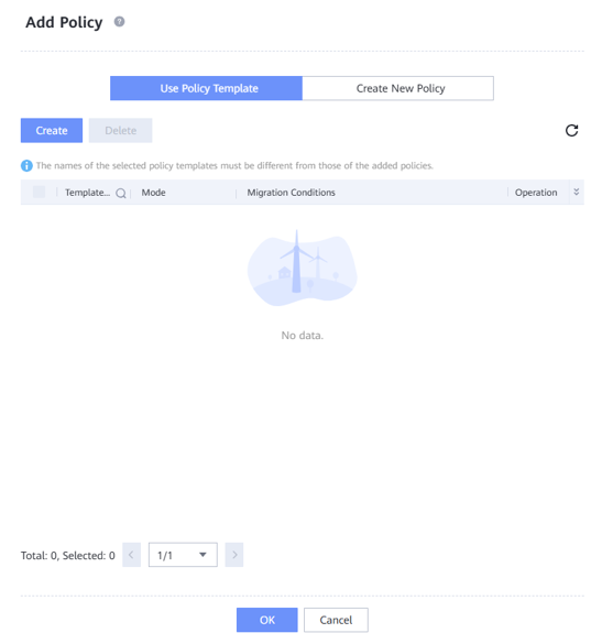
Step 7 Click OK to create SmartMobility.
—-End
4.8.2.6 (Optional) Enabling Tiered Link Deduplication
Step 1 Choose Services > Resource Tuning > SmartMobility > SmartMobility.
Step 2 Select the SmartMobility file system for which you want to enable link deduplication.
Step 3 In the Basic Information area, click Modify. In the Modify Basic Information dialog box that is displayed, enable Link deduplication.

4.9 Best Practice Verification Examples
The performance test result does not apply to the scenario of upgrade from an earlier version. For details about the performance in the upgrade scenario, contact R&D engineers for evaluation.
4.9.1 Backup and Restoration Bandwidth Performance Test Results of High-Configuration Servers
When Commvault is used to back up Oracle and VMware data:
This solution tests the backup performance when the WORM feature is enabled and disabled. The test conclusions are as follows:
- The WORM feature takes effect. After the WORM feature is enabled, copies backed up to OceanProtect X8000 cannot be modified or deleted.
- There is no obvious difference in the backup bandwidth and restoration bandwidth performance when WORM is enabled compared with those when WORM is disabled.
In this high-performance scenario, two solutions in 3.3.4 Commvault Deployment Planning are tested: one-to-one solution (one file system to MediaAgent) and one-to-many solution (one file system to multiple MediaAgents). The detailed performance test scenarios are as follows:
- Production environment: Commvault is used to back up three Oracle hosts and three ESXi hosts.
a. Each Oracle host is preset with 40 to 60 data files. The size of each data file ranges from 36 GB to 54 GB. The size of each database ranges from 2.2 TB to 2.3 TB. The total data volume of the three Oracle databases is about 7 TB.
- Backup environment: OceanProtect X8000 (all-flash). Create a file system and connect it to six Commvault MediaAgents through DataTurbo.
- Test model: In the backup performance test, the first, second, and third full backups are performed with 5% data changed each time. In the restoration performance test, all VMs and Oracle database instances that have been backed up are restored.
- Library solution planning: a. One-to-one mapping between file systems and MediaAgents: OceanProtect X8000 uses six file systems and six MediaAgents. One file system is mounted to one MediaAgent and each mount directory is created as a unique mount path in a library. Table 4-6 describes the test results of the maximum bandwidth performance between the high performance and high reduction ratio compression modes of OceanProtect.
Each ESXi host has eight VMs to be backed up. Each VM contains six disks, including one 50 GB system disk and five 120 GB data disks, and a total of 500 GB data is preset in the data disks. Therefore, there is 11.5 TB data in total for backup of 24 VMs.
b. One-to-many solution (one file system to multiple MediaAgents): OceanProtect X8000 uses one file system and six MediaAgents. One file system is mounted to the six MediaAgents and each mount directory is created as a unique mount path in a library. Table 4-7 describes the maximum bandwidth performance of the high reduction ratio compression mode of OceanProtect.
Table 4-6 Backup and restoration bandwidth performance test results of the one-to-one solution for file systems and MediaAgents
Compression Mode | Backup Type | Peak Backup Bandwidth (GB/s) | Backup Data Volume (TB) | Backup Duration (min) | Average Backup Bandwidth (GB/s) |
|---|---|---|---|---|---|
High performance | Initial backup | – | 18.5 | 26 | 11.93 |
Second backup | 20.1 | 18.5 | 25 | 12.40 | |
Third backup | 20.1 | 18.5 | 24 | 12.92 | |
Restoration | 7.5 | 18.5 | 67 | 4.63 | |
High reduction ratio | Initial backup | – | 18.5 | 40 | 7.75 |
Second backup | 19.5 | 18.5 | 23 | 13.48 | |
Third backup | 18.5 | 18.5 | 25 | 12.40 | |
Restoration | 6.7 | 18.5 | 70 | 4.43 |
Table 4-7 Backup and restoration bandwidth performance test results of the one-to-many solution (one file system to multiple MediaAgents)
Compression Mode | Backup Type | Peak Backup Bandwidth (GB/s) | Backup Data Volume (TB) | Backup Duration (min) | Average Backup Bandwidth (GB/s) |
|---|---|---|---|---|---|
High reduction ratio | Initial backup | – | 18.5 | 39 | 7.9 |
Second backup | 20 | 18.5 | 23 | 13.5 | |
Third backup | 18.5 | 18.5 | 24 | 12.9 | |
Restoration | 6.65 | 18.5 | 73 | 4.25 |

The high performance mode and the high reduction ratio mode in Table 4-6 and Table 4-7 are set as follows:
- High performance mode: Set the compression mode of the storage pool to High performance and the file system application type to Performance_Global_Mode.
- High reduction ratio mode: Set the compression mode of the storage pool to High reduction ratio and the file system application type to Reduction_Global_Mode.
Restoration performance:
- Some restoration jobs are slow. As a result, the overall restoration process takes a long time.
- The restoration bandwidth closely depends on the performance of the restoration destination host. The test results do not represent the maximum restoration capability of OceanProtect X8000.
4.9.2 Backup Bandwidth Performance Test Results of Typical-Configuration Servers
When Commvault is used to back up VMware VMs:
- The GridStor solution in 3.3.4 Commvault Deployment Planning is tested in the typical server configuration scenario. Two libraries are created. For details, see Figure 3-11.
- Production environment: Commvault is used to back up four ESXi hosts, including 32 VMs. 500 GB data is preset on each VM. The total data volume is about 14.5 TB.
- Backup environment: OceanProtect X8000 (all-flash). Two file systems are created and connected to four MediaAgents through DataTurbo. The MediaAgent server uses typical configuration: 2 x Intel(R) Xeon(R) Silver 4214R CPU and 16 x 16 GB memory.
- Test model: The first and second full backups are tested with 5% data volume changed each time. In the restoration performance test, all VMs and Oracle database instances that have been backed up are restored.
- Table 4-8 describes the performance result.
Table 4-8 Backup and restoration bandwidth performance test results when Commvault is used to back up VMware VMs and four MediaAgents are deployed
Compression Mode | Backup Type | Peak Backup Bandwidth (GB/s) | Backup Data Volume (TB) | Backup Duration (min) | Average Backup Bandwidth (GB/s) |
|---|---|---|---|---|---|
High performance | Initial backup | 6.3 | 14.5 | 61 | 4.06 |
Second backup | 6.7 | 14.5 | 65 | 3.81 | |
Restoration | 4.1 | 14.5 | 70 | 3.53 | |
High reduction ratio | Initial backup | 5.6 | 14.5 | 71 | 3.49 |
Second backup | 7 | 14.5 | 70 | 3.53 | |
Restoration | 3.9 | 14.5 | 66 | 3.75 |

- The backup and restoration speeds vary greatly with VMs in a job. The backup and restoration of some VMs are too slow. As a result, the overall job runs for a long time.
- The restoration bandwidth closely depends on the performance of the restoration destination host. The test results do not represent the maximum restoration capability of OceanProtect X8000.
4.9.3 Data Reduction Test Results
When Commvault is used to back up Oracle databases and file systems, use Commvault to back up 10 Oracle hosts and two file system hosts to perform a data reduction test. OceanProtect X8000 is configured in high reduction ratio mode. The production data and backup policies are as follows:
- Preset data model:
- There are two file system hosts. One LUN is mounted to each file system host. Two directories are created, with 100 files preset in each directory. The size of each file is 30 GB. The deduplication ratio is 1.3:1, and the compression ratio is 2:1.
- There are 10 Oracle databases. Each Oracle host is preset with 40 to 60 data files. The size of each data file ranges from 36 GB to 54 GB, and the size of each database ranges from 1.7 TB to 2.1 TB.
- Backup policy: Initial, second, and third full backups.
- Backup data difference: Data in the file system and Oracle database changes by 5% between two backups.
Table 4-9 lists the end-to-end data reduction test results.
Table 4-9 Data reduction test results when Commvault is used to back up Oracle databases and file systems
Backup Type | Number of Oracle Databases | Number of File Systems | Data Volume (TB) | Data Reduction Ratio |
|---|---|---|---|---|
Initial full backup | 10 | 2 | 30.97 | 3.576:1 |
Second full backup | 10 | 2 | 30.97 | 6.726:1 |
Third full backup | 10 | 2 | 30.97 | 9.543:1 |
When Commvault is used to back up VMware VMs, use Commvault to back up eight VMs and perform a data reduction test. The production data and backup policies are as follows:
- Preset data model: There are eight VMs, and more than 5000 files are preset on each VM. The data volume is 450 GB. The total data volume of the eight VMs is around 3.71 TB.
- Backup policy: Initial, second, and third full backups.
- Backup data difference: Construct 5% data volume change of the VM between two backups.
Table 4-10 lists the end-to-end data reduction test results.
Table 4-10 Data reduction test results of a single MediaAgent when Commvault is used to back up VMware VMs
Compression Mode | Backup Type | Number of VMs | Data Volume (TB) | Data Reduction Ratio |
|---|---|---|---|---|
High performance | Initial full backup | 8 | 3.71 | 4.232:1 |
Second full backup | 8 | 3.71 | 7.779:1 | |
Third full backup | 8 | 3.71 | 10.726:1 | |
High reduction ratio | Initial full backup | 8 | 3.71 | 5.062:1 |
Second full backup | 8 | 3.71 | 9.241:1 | |
Third full backup | 8 | 3.71 | 12.781:1 |

- High reduction ratio mode: Set the compression mode of the storage pool to High reduction ratio and the file system application type to Reduction_Prioritized_Mode_enhanced.
- Data reduction ratio: indicates the ratio of the amount of user data written into the storage pool to the used capacity of the storage pool.
- The actual data reduction ratio is closely related to the data model and the backup policy. The test results are based on the preceding backup policy and data model.
4.9.4 Remote Replication Test Results
Two OceanProtect X8000 devices are used to form a remote replication environment.
- Networking: Use two 10GE network cables to connect the two OceanProtect X8000 devices to the same switch to form a replication network, and create a remote device.
- Remote replication configuration: Enable deduplicated replication and link compression, and change the rate to the highest.
- Backup data difference: data changes by 5% between two backup jobs, and Oracle archive logs are not disabled during data reconstruction.
Table 4-11 Data reduction test results
Backup Type | Data Volume (GB) | Link Data Reduction Ratio | Backup Duration (s) | Average Bandwidth (GB/s) |
|---|---|---|---|---|
First remote replication | 507.34 | 3.345:1 | 405 | 1.25 |
Second remote replication | 549.58 | 46.088:1 | 155 | 3.55 |
4.9.5 Synthetic Full Backup Test Results
Use Commvault to back up VMware VMs to perform a synthetic full backup test. OceanProtect X8000 is configured in high reduction ratio mode, and Commvault is enabled with data deduplication. The production data and backup policies are as follows:
- Preset data model: There are eight VMs, and more than 5000 files are preset on each VM. The data volume is 450 GB. The total data volume of the eight VMs is around 3.71 TB.
- Backup policy: Full backup, five incremental backups, and synthetic full backup.
- Backup data difference: Construct 5% data volume change of the VM between two backups. Do not construct data changes before the synthetic full backup.
Table 4-12 Data reduction test results
Backup Type | Data Volume (GB) | Link Data Reduction Ratio | Backup Duration (s) | Average Bandwidth (GB/s) |
|---|---|---|---|---|
Full backup | 3789 | 5.01:1 | 2869 | 1.32 |
Five incremental backups | – | – | – | – |
Synthetic full backup | 3789 | 8.56:1 | 3343 | 1.13 |