OceanProtect V200R001C33 Backup Storage Solution Best Practices (Integrating OpenText Data Protector)
Interoperability Test Report

Axians Global All Rights Reserved
Overview
This document describes best practices of VMware backup based on the OceanProtect Backup Storage integrating backup software OpenText Data Protector.
Intended Audience
This document is intended for:
- Marketing engineers
- Technical support engineers
Symbol Conventions
Symbols that may be found in this document are defined as follows.
Symbol | Description |
|---|---|
 | Indicates a hazard with a high level of risk which, if not avoided, will result in death or serious injury. |
 | Indicates a hazard with a medium level of risk which, if not avoided, could result in death or serious injury. |
 | Indicates a hazard with a low level of risk which, if not avoided, could result in minor or moderate injury. |
 | Indicates a potentially hazardous situation which, if not avoided, could result in equipment damage, data loss, performance deterioration, or unanticipated results. NOTICE is used to address practices not related to personal injury. |
 | Supplements the important information in the main text. NOTE is used to address information not related to personal injury, equipment damage, and environment deterioration. |
Change History
Issue | Date | Description |
|---|---|---|
01 | 2026-07-30 | This issue is the first official release. |
1. Solution Overview
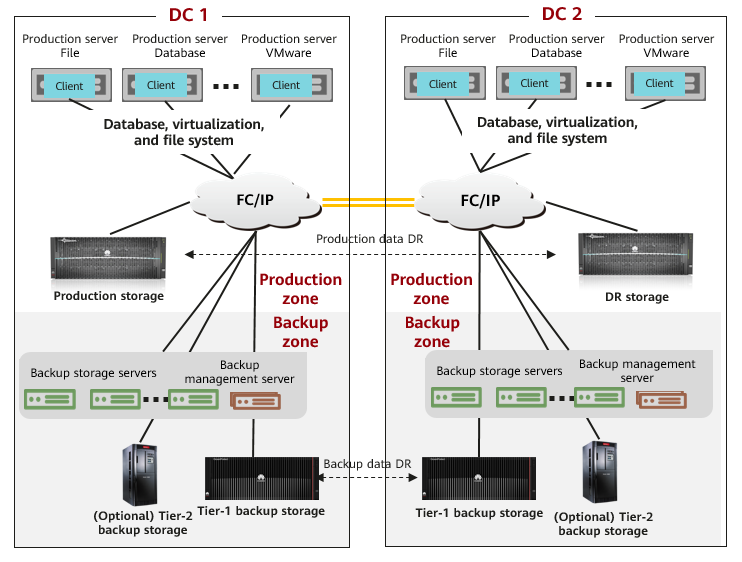
The backup storage solution provides a backup system with software and hardware deployed independently. It includes the backup software, backup agent, backup management server, backup storage server, and backup storage. Figure 1-1 shows the solution architecture.
Figure 1-1 Backup storage solution architecture
Solution Components
- Backup software: Mainstream backup software includes Data Protector, NetWorker, Veritas NetBackup, Veeam, and Commvault.
- Backup management server: It manages components in the backup system. It is used to create, execute, and schedule backup jobs and configure backup policies. It can be deployed independently or together with the media server.
- Backup agent client: It is installed on protected application production servers and VMs, responds to backup job scheduling by the backup management server, collects and manages data to be protected, and transmits the data to the backup storage server.
- Backup storage server (also called media server): It is deployed independently and responds to job scheduling by the backup management server. It processes backup data flows and manages backup data transmission and storage devices. Some vendors provide backup data deduplication and compression on the backup storage server.
- Backup storage: It is connected to the backup storage server and used to receive and store backup data. Some backup storage devices provide deduplication and compression. Based on service requirements, there are tier-1 backup storage and tier-2 backup storage. Tier-1 backup storage provides rapid and efficient backup and restoration with optimal performance. As tier-1 backup storage is expensive, deduplication and compression are important. Tier-2 backup storage provides long-term retention (LTR) at a low cost. Backup copies before a certain point in time can be migrated to tier-2 backup storage for an optimal comprehensive retention cost. Common backup storage types include backup storage, general-purpose storage, virtual tape library (VTL), object storage, and tape library.
Solution Description
- During backup, the backup management server delivers a backup scheduling command to the backup agent. Then, the backup agent collects and transmits data based on the set backup policy. The backup storage server processes the data transmitted by the backup agent, writes the data to the backup storage in a certain format, and records indexes.
- Performance of a single backup storage server is limited. Backup storage server scale-out is supported for performance improvement.
- Backup data replication: Remote backup data DR is required to meet compliance and data security requirements. Data can be replicated and transmitted through the backup storage server or tier-1 backup device.
- Backup data LTR: LTR solutions apply to scenarios where backup copies need to be retained for a long time with rapid restoration available. Based on policies, latest copies are stored on tier-1 backup media with rapid backup, access, and restoration supported. Copies that need to be retained for a long time are stored on tier-2 backup media with lower costs. In this way, the overall retention cost is optimal.
2. Solution Introduction
Based on Huawei OceanProtect backup storage integrating Data Protector, the backup storage solution provides application system backup, backup copy replication, LTR, and dumping of backup copies from peer vendors’ systems.
2.1 Solution Components
2.1.1 Data Protector Backup Software
Data Protector is a backup solution provided by OpenText. It provides reliable data protection and high accessibility for rapidly growing service data.
Data Protector offers comprehensive backup and restoration functions specifically tailored for enterprise-wide and distributed environments.
Main Functions of Data Protector
- Scalable and highly flexible architecture
- Support for hybrid environments
- Convenient centralized management
- High-performance backup
- Easy restoration
- Data and control communication security
- High availability
- Automatic or unattended operation
- Monitoring, reporting, and notification
- Service management
- Integration with online database applications
- Integration with other products
Components of Data Protector
Data Protector can be used in various environments, covering one system to thousands of systems at different sites. The basic management unit is the Data Protector cell.
A Data Protector cell is a network environment containing the Cell Manager system, one or more Installation Servers, client systems, and devices.
The Cell Manager and Installation Servers can be on the same system (by default) or on different systems.
Cell Manager
The Cell Manager is the main system that controls the Data Protector cell from a central point, with the Data Protector core software and the IDB installed. The Cell Manager runs various Session Managers that control backup and restoration sessions and write session information to the IDB. The IDB traces backup files and Data Protector cell configuration.
Installation Server
An Installation Server is a computer that stores the Data Protector software repository. There must be at least one Installation Server for UNIX and one for Windows so that you can perform remote installation through the network and distribute software components to the client systems in the cell.
Client System
After the Data Protector software is installed on the Cell Manager system, Data Protector components can be installed on each system in the cell. These systems become Data Protector clients. Functions of a client depend on the Data Protector software installed on the system.
- System to be backed up
A client system to be backed up must have the Data Protector Disk Agent (DA, also called a backup agent) installed. The DA reads data from or writes data to disks on the system and sends data to or receives data from the Media Agent (MA). The DA is also installed on the Cell Manager so that the Cell Manager data, Data Protector configurations, and IDB can be backed up.
- System connected to a backup device
A client system connected to a backup device must have the Data Protector MA installed. The MA reads data from or writes data to media in the device and sends data to or receives data from the DA. The backup device can be connected to any system besides the Cell Manager. A client system connected to a backup device is also called a driver server. A client system connected to multiple backup devices is called a multi-driver server.
Reporting Server
The Reporting Server is a component of Data Protector used to view integrated reports for managing and planning backup environments. The Reporting Server must be installed on a server other than a Data Protector Cell Manager.
2.1.2 OceanProtect Backup Storage
Product Positioning
As the amount, types, and growth rate of data change exponentially, enterprises face increasing data loss risks due to human errors, viruses, natural disasters, and network security threats. Therefore, data protection becomes increasingly important.
OceanProtect backup storage features rapid backup, rapid restoration, efficient reduction, and solid resilience. It implements efficient backup and restoration with the TCO greatly reduced. It is widely used in government, finance, carrier, healthcare, and manufacturing industries. In addition, it offers easy management and convenient local/remote maintenance, significantly reducing device management and maintenance costs.
OceanProtect backup storage is available in SSD and HDD forms.
- SSD form: The system supports only SSDs. Service data and metadata are stored on SSDs.
- HDD form: The system supports SSDs and HDDs. Service data is stored on a storage pool composed of HDDs. SSDs only store system metadata. SSDs delivering higher performance accelerate metadata access, improving read and write performance.
Product Highlights
With the active-active high-reliability architecture and full-process acceleration, OceanProtect backup storage features rapid backup, rapid restoration, efficient reduction, and solid resilience.
In addition, OceanProtect 1.2.0 provides source deduplication and deduplicated replication to effectively save the logical bandwidth and decrease network resource occupation.
- Rapid backup and restoration
- Full-process acceleration is implemented. The front-end network protocol offload technology reduces the CPU pressure, and back-end CPU multi-core parallel scheduling is implemented. Dedicated cores are used through grouping and task partitioning, efficiently improving the processing capability of nodes.
- Based on backup service characteristics, multiple sequential data flows are aggregated for read and write, greatly improving bandwidth performance. Source deduplication reduces the amount of data to be transmitted over the network, shortening the backup duration.
- The system provides high IOPS performance and can work with mainstream backup software. Backup image data can be accessed instantly, enabling fast utilization of backup data.
- Efficient reduction
- Accurate backup data segmentation, backup data aggregation preprocessing, and multi-layer inline variable-length deduplication are used to increase the logical capacity and reduce the TCO.
- Data flow features can be identified. Combination-based compression, high-performance predictive encoding, and byte-level compaction are used to improve the data reduction ratio.
- Source deduplication and deduplicated replication are used to reduce network bandwidth costs.
- Solid resilience
- The active-active redundant hardware architecture design ensures that ongoing backup jobs, if a controller is faulty, can be switched over in seconds without being interrupted.
- Protocol encryption, replication link encryption, storage encryption, secure snapshot, and WORM functions are used to ensure security and availability of copies.
2.2 Solution Architecture
2.2.1 Overall Solution Architecture
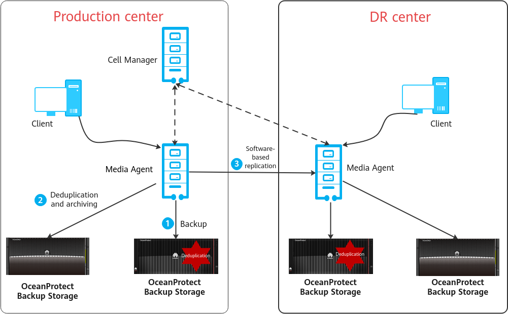
Figure 2-1 Overall architecture of the OceanProtect Backup Storage+Data Protector solution
Solution overview:
- Backup and restoration
S3-based backup is supported, but source deduplication is not supported.
Deduplication in the OceanProtect storage does not occupy the computing power of the backup server.
- Remote replication
The Object Copy function of Data Protector is used to replicate backup copies to the storage in the DR center.
After the replication is complete, the MA in the DR center can restore the backup copies to the application system.
- Tiering for LTR
Data Protector can copy backup objects and create object copy tasks to implement automatic tiering to the OceanProtect Backup Storage.
2.2.2 Backup Solution Architecture
Figure 2-2 Backup solution architecture
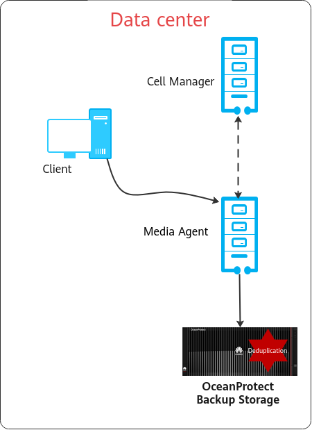
Backup solution architecture overview:
- Cell Manager
The Cell Manager is the main system that controls the Data Protector cell from a central point, where the Data Protector core software with the IDB is installed. The Cell Manager runs Session Managers that control backup and restoration sessions and write session information to the IDB.
- DA
Client systems to be backed up must have the DA (also called backup agent) installed. The DA reads data from or writes data to disks on the system and sends data to or receives data from the MA. Generally, it is deployed on the same node as the MA.
- MA
The MA reads data from or writes data to media in the device and sends data to or receives data from the DA.
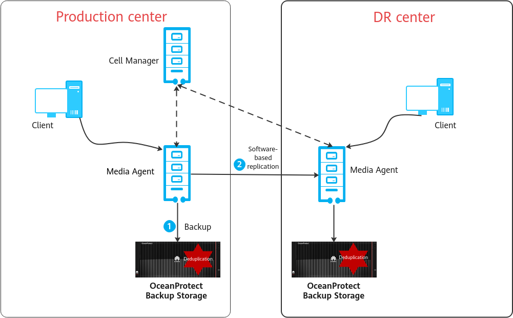
2.2.3 Backup Copy Replication Solution Architecture
- Scenario
Backup copies can be replicated within a backup domain. When backup copies in one MA need to be replicated to another MA, the backup copies in the production center are remotely replicated to the DR center. The solution uses the Object copy function of Data Protector for efficient copy replication.
- Replication mode
One-to-one and one-to-many
Automatic replication (post-backup or scheduled replication) and manual replication
- Replication description
- The Cell Manager manages local and remote MAs and remotely replicates backup data using the Object copy function.
- The desired backup copy of the target MA is selected from the Cell Manager for data restoration.
- You can configure a retention policy for each backup copy and control each copy as required.
Figure 2-3 Replication using the OceanProtect Backup Storage integrating Data Protector
2.2.4 Tiering Solution Architecture
Figure 2-4 Tiering solution architecture
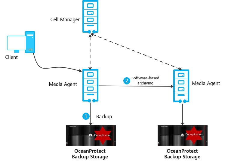
Tiering solution architecture overview:
The Data Protector software tiers data from the OceanProtect Backup Storage to the OceanProtect Backup Storage.
Production data is backed up to the OceanProtect Backup Storage for short-term retention.
Data Protector can copy backup objects and create object copy tasks to implement automatic tiering to the OceanProtect Backup Storage for long-term data retention.
Tiered copies can be directly used for data restoration.
3. Planning Suggestions
3.1 Network Planning for Different OceanProtect Models
3.2 Planing for System Backup Capacity and Performance
3.3 OceanProtect X8000 Configuration Planning
3.4 OpenText Data Protector Backup Planning
3.1 Network Planning for Different OceanProtect Models
A customer can select the OceanProtect X3000, X6000, X8000, and X9000 Backup Storage based on backup capacity and performance requirements. The networking configuration principles of all models comply with those described in 4.3 Configuration Planning for Data Protector Integration.
3.2 Planing for System Backup Capacity and Performance
- Backup capacity calculation
Generally, capacity of OceanProtect X8000 is planned based on the backup data capacity and retention period. In this best practice, 25 SSDs (3.84 TB each) are used.
- Backup performance calculation
Generally, backup performance of a backup system is planned based on the backup time window and backup capacity. In this best practice, the backup performance is 2 GB/s.
3.3 OceanProtect X8000 Configuration Planning
Storage Resource Planning
- Disk type planning: Storage pools can be created using SSDs and HDDs. Table 3-1 describes disk type planning.
Table 3- 1 Disk type planning
Storage Form | OceanProtect X8000 (All-Flash) | OceanProtect X8000 (HDD) |
Disk Type | A storage pool contains only SSDs. | A storage pool contains SSDs and HDDs. |
Disk Quantity |
|
|
- Storage capacity planning: Generally, capacity of OceanProtect X8000 is planned based on the backup data capacity and retention period.
- Compression mode planning: Storage pools support high reduction ratio (default) and high performance compression modes.
The high reduction ratio mode delivers higher reduction ratio than the high performance mode.
- Storage pool planning: A storage pool is a container that stores resources. It provides storage space for all application servers. For core services, RAID-TP is recommended. Table 3-2 describes storage pool protection levels.
Table 3-2 Storage pool protection levels
Protection Level | Number of Parity Bits | Redundancy and Data Restoration | Maximum Number of Disks Allowed to Fail Simultaneously |
|---|---|---|---|
RAID 6 (default) | 2 | High. Parity data is distributed in different chunks (CKs). In each chunk group (CKG), parity data occupies the space of two CKs. The failure of any two CKs can be tolerated. If three or more CKs fail simultaneously, RAID 6 protection cannot be provided. | 2 |
RAID-TP | 3 | High. Parity data is distributed in different CKs. In each CKG, parity data occupies the space of three CKs. The failure of any three CKs can be tolerated. If four or more CKs fail simultaneously, RAID-TP protection cannot be provided. | 3 |
File System Planning
- File system planning: Table 3-3 describes key parameters in file system planning.
Table 3-3 File system planning
Parameter | Description |
|---|---|
Capacity | File system capacity is planned based on service requirements. |
Quantity | To ensure performance, it is recommended that four file systems be configured. |
Application type |
|
- File system sharing: OceanProtect X8000 provides CIFS, NFS, and DataTurbo shares. Source deduplication is planned in this solution. Currently, DataTurbo shares support TCP or Fibre Channel networks. Therefore, select the DataTurbo share for file system sharing. For details about OS and backup software versions supported by the DataTurbo client, visit the compatibility website.

Compatibility query website: https://info.support.huawei.com/storage/comp/#/oceanprotect
TCP Network Planning
- Physical port planning
- Quantity planning: When source deduplication is enabled, the required physical bandwidth can be planned based on the number of backup hosts. Planning 2 x 10GE for each backup host can meet bandwidth requirements. For example, if there are four backup hosts, eight physical ports are needed for the back-end OceanProtect X8000.
- Configuration planning: An OceanProtect X8000 device has two controllers. To ensure reliability, NICs must be evenly distributed to controllers A and B.
- Logical port planning
- Quantity planning: Logical ports are created for running NAS services. It is recommended that at least one logical port be configured for each physical port.
- Configuration planning: An OceanProtect X8000 device has two controllers (A and B). It is recommended that 2 x 10GE of a backup host be connected to the logical ports of controllers A and B on OceanProtect X8000, respectively.
Fibre Channel Network Planning
- Physical port planning
- Quantity planning: When source deduplication is enabled, the required physical bandwidth can be planned based on the number of backup hosts. 2 x 16 Gbit/s for each backup host can meet bandwidth requirements. For example, if there are four backup hosts, eight physical ports are needed for the back-end OceanProtect X8000.
- Configuration planning: An OceanProtect X8000 device has two controllers. To ensure reliability, NICs must be evenly distributed to controllers A and B.
3.4 OpenText Data Protector Backup Planning
In this solution, the S3 protocol is used for integration with OceanProtect X8000. The Data Protector backup software must be deployed on the Data Protector server.
- Server requirements: Plan the number of servers based on the required backup network bandwidth.
- OS requirements: For details about Data Protector’s requirements on OSs, see the official documents of Data Protector. The OceanStor DataTurbo software must be deployed on Data Protector servers with compatibility requirements met. For details, visit the compatibility query website: https://info.support.huawei.com/storage/comp/#/oceanprotect.
- NIC requirements: The Data Protector backup server must be connected to the production system and backup storage device. Front- and back-end NICs must meet backup bandwidth requirements to avoid bottlenecks.
- Front-end network: It is used to establish connection with the production environment. Therefore, the backup capability requirement of each Data Protector backup server must be met to prevent the front-end network configuration from becoming a bottleneck. In this solution, the capability of a single Data Protector backup server is evaluated as 5 GB/s, and the front-end network requires 4 × 10GE, which can be adjusted based on the actual MA capability in tests.
- Back-end TCP network: This solution uses source deduplication. Therefore, the back-end network of the Data Protector backup server does not need to have the same configurations as the front-end network. You are advised to configure 2 × 10GE for each Data Protector backup server for connecting to controllers A and B of OceanProtect X8000, respectively.
- Back-end Fibre Channel network: This solution uses source deduplication. Therefore, the back-end network of the Data Protector backup server does not need to have the same configurations as the front-end network. You are advised to configure 2 × 16 Gbit/s for each Data Protector backup server to connect to controllers A and B of OceanProtect X8000, respectively.

For good deduplication performance, you are advised to disable the deduplication and compression functions of the backup software and disable the compression and encryption functions of the applications to be backed up.
4.Configuration Example
In this chapter, OceanProtect X8000 (with source deduplication provided) integrates Data Protector to back up VMware applications. Backup and restoration configuration processes as well as test results are provided.
4.2 Hardware and Software Configuration
4.3 Configuration Planning for Data Protector Integration
4.4 Data Protector Backup and Restoration Configuration
4.5 S3-based Backup and Restoration Configuration Example
4.6 Data Protector Software–based Replication and Tiering
4.7 Best Practice Verification
4.1 Solution Networking
Figure 4-1 shows an example of the TCP networking diagram of this best practice.
Figure 4-1 TCP networking diagram for VMware backup using OceanProtect X8000 integrating Data Protector
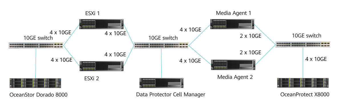

Figure 4-1 is only an example. For details about connections between OceanProtect X8000 controller enclosures and application servers, between controller enclosures and disk enclosures, and between controller enclosures, see « Cabinet Layout and Connection Planning » in the OceanProtect X6000, X8000 1.x Installation Guide.
The TCP networking is described as follows:
- VMware: Two physical ESXi hosts are deployed with one production storage device connected.
- The two ESXi hosts are connected to OceanStor Dorado 8000 through a 10GE switch. Each ESXi host uses 4 x 10GE iSCSI links. OceanStor Dorado 8000 uses 8 x 10GE links.
- LUNs are created on OceanStor Dorado 8000 and mounted to the ESXi hosts through the iSCSI protocol. These LUNs are used for storing ESXi host data.
- Each ESXi host uses 4 x 10GE optical fibers for configuring a bond port (mode 0) to connect to the Data Protector MAs through a 10GE switch.
- Data Protector Cell Manager: It is deployed on a VM only for role assignment and service scheduling.
- Data Protector MA: Two MAs are connected to the ESXi hosts through a 10GE switch and connected to OceanProtect X8000 through a 10GE switch.
- Two MAs use four 10GE ports for port binding (in mode0) and are connected to ESXi hosts through a 10GE switch. Eth-Trunk is configured on the switch.
- Each MA uses two 10GE ports to connect to the 10GE switch and to establish a connection between the switch and OceanProtect X8000.
- OceanProtect X8000: connects to a switch through 4 x 10GE optical fibers. Each controller uses 2 x 10GE optical fibers. Four physical ports connect to the backup server for backup links.
Figure 4-2 shows an example of the Fibre Channel networking diagram of this best practice.
Figure 4-2 Fibre Channel networking diagram for VMware backup using OceanProtect X8000 integrating Data Protector
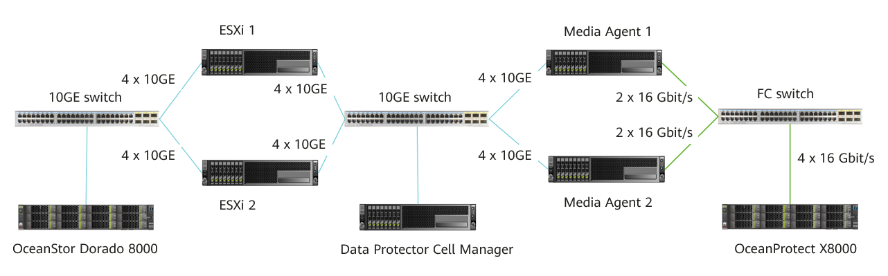

Figure 4-2 is only an example. For details about connections between OceanProtect X8000 controller enclosures and application servers, between controller enclosures and disk enclosures, and between controller enclosures, see « Cabinet Layout and Connection Planning » in the OceanProtect X6000, X8000 1.x Installation Guide.
The Fibre Channel networking is described as follows:
- VMware: Two physical ESXi hosts are deployed with one production storage device connected.
- The two ESXi hosts are connected to OceanStor Dorado 8000 through a 10GE switch. Each ESXi host uses 4 x 10GE iSCSI links. OceanStor Dorado 8000 uses 8 x 10GE links.
- LUNs are created on OceanStor Dorado 8000 and mounted to the ESXi hosts through the iSCSI protocol. These LUNs are used for storing ESXi host data.
- Each ESXi host uses 4 x 10GE optical fibers for configuring a bond port (mode 0) to connect to the Data Protector MAs through a 10GE switch.
- Data Protector Cell Manager: It is deployed on a VM only for role assignment and service scheduling.
- Data Protector MA: Two MAs are connected to the ESXi hosts through a 10GE switch and connected to OceanProtect X8000 through a 10GE switch.
- The two MAs use four 10GE ports for port binding (in mode0) and are connected to ESXi hosts through a 10GE switch. Eth-Trunk is configured on the switch.
- Each MA uses two 16 Gbit/s ports to connect to the Fibre Channel switch and to establish a connection between the switch and OceanProtect X8000.
- OceanProtect X8000: connects to a Fibre Channel switch through 4 x 16 Gbit/s optical fibers. Each controller uses 2 x 16 Gbit/s optical fibers. Four physical ports connect to the backup server for backup links.
4.2 Hardware and Software Configuration
4.2.1 Hardware Configuration
Name | Description | Quantity | Function |
|---|---|---|---|
Data Protector Cell Manager | VM running the Windows OS | 1 | Management node used to deploy and manage all Data Protector roles and schedule tasks. |
MA | x86 server CPU: 2 x Intel(R) Xeon(R) Silver 4208 Memory: 32 GB Network: 6 x 10GE optical ports | 2 | Data Protector backup media server which reads and writes backup data and manages Data Protector storage media. It is used for DataTurbo plug-in installation and OceanProtect file system mounting. |
ESXi server | x86 server CPU: 2 x Intel(R) Xeon(R) Gold 6130 Memory: 256 GB Network: 4 x 10GE optical ports | 2 | ESXi host where VMs to be backed up are deployed. |
Production storage | Huawei OceanStor Dorado 8000 with two controllers, 26 x 7.68 TB SSDs, and 4 x 4-port 10 Gbit/s SmartIO interface modules | 1 | Production storage that stores production service data to be backed up and tested. |
Backup service switch | Huawei CE6850 | 2 | 10GE switch on the backup service plane. |
4.2.2 OceanProtect X8000 (All-Flash) Configuration
Table 4-1 OceanProtect X8000 (all-flash) configuration
Name | Description | Quantity |
|---|---|---|
OceanProtect engine | Huawei OceanProtect X8000 with two controllers | 2 |
10GE front-end interface module | 4 x 10 Gbit/s SmartIO interface modules | 2 |
SAS SSD | Huawei 7.68 TB SAS SSDs | 25 |
4.2.3 Test Software and Tools
Table 4-2 Software description
Software Name | Description |
|---|---|
OceanProtect-BackupStorage_V200R001C30_DataTurbo | Source deduplication client software. It is deployed on the backup server for source deduplication and compression on backup data to reduce the amount of physical data transmitted from the backup server to storage and improve the overall bandwidth of backup services. |
OpenText Data Protector | Data Protector 23.4 backup software |
ESXi | VMware ESXi host |
CentOS 7.6 | CentOS Linux open-source OS |
Vdbench | Third-party tool for generating VMware test data |
SSH client software | SSH terminal connection tool |
4.3 Configuration Planning for Data Protector Integration
- Storage pool on OceanProtect X8000: Create a storage pool with 10 x 3.84 TB SAS SSDs, and configure RAID 6.
- OceanProtect X8000 file system: Take two backup media servers as an example. Plan two file systems for the two controllers (one for each controller) and 100 TB logical capacity for each file system.
- Logical ports of OceanProtect X8000: OceanProtect X8000 is connected to the two front-end backup media servers through 4 x 10GE physical links. Each physical port is configured with one logical port.
- Storage pool planning:
- On OceanProtect X8000, create two file systems that are owned by controllers A and B, respectively.
- Mount one file system to each backup media server.
- Create one device at each mount point on each backup media server. There are two devices in total.
Figure 4-3 shows the mounting details.
Figure 4-3 Mounting file systems
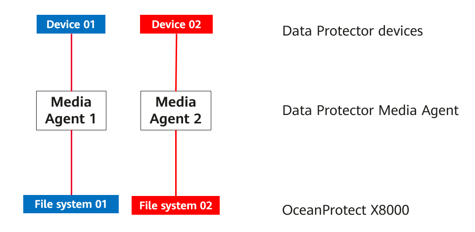

Backup principle: Periodic backup copy data of the same type of applications is written to the same deduplication domain.
Networking principles:
- It is recommended that one device be planed for a type of applications. The mapping relationship between devices and file systems or backup media servers is one-to-one.
- To maximize the performance of X9000 HDDs, 16 file systems are required.
4.4 Data Protector Backup and Restoration Configuration
4.4.1 Configuration Process
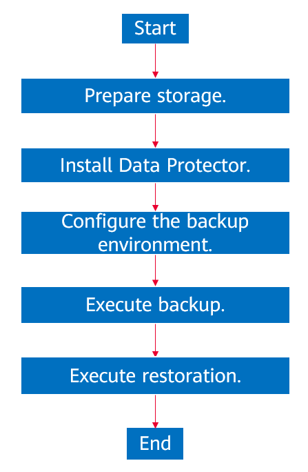
Figure 4-4 Solution configuration process
4.4.2 Preparing Storage
According to planning in this solution, create two file systems and a DataTurbo share on OceanProtect X8000. The configuration procedure is as follows: Create a storage pool, create logical ports, create a file system, and create a share.
4.4.2.1 Creating a Storage Pool on OceanProtect X8000
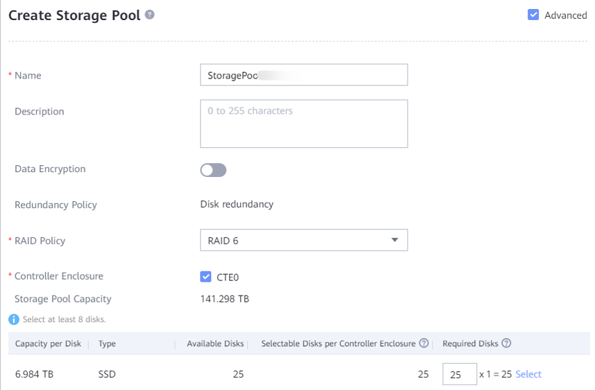
Step 1 On OceanProtect X8000, select 25 disks to create a storage pool and set the RAID policy to RAID 6.
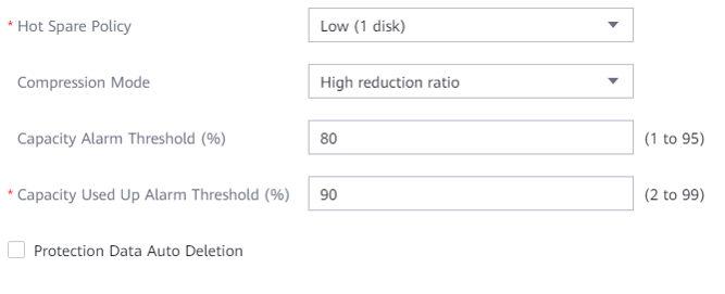
Step 2 Click Advanced, and select the high reduction ratio (default) or high performance mode for the compression mode.
—-End
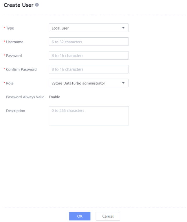
4.4.2.2 Creating a vStore DataTurbo Administrator
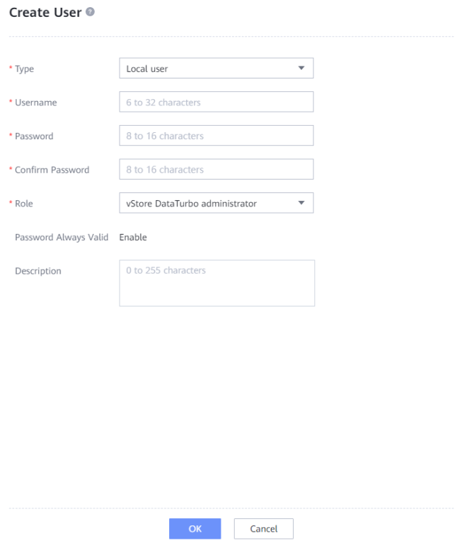
Choose Services > vStore Services > vStores > System_vStore > User Management, and click Create. Set Role to vStore DataTurbo administrator, enter the username in the Username field, enter the password in Password and Confirm Password fields, and click OK.
4.4.2.3 Creating Logical Ports on OceanProtect X8000 (TCP Networking)
This operation is required when a DataTurbo over TCP network is used, and is not required when a Fibre Channel network is used.
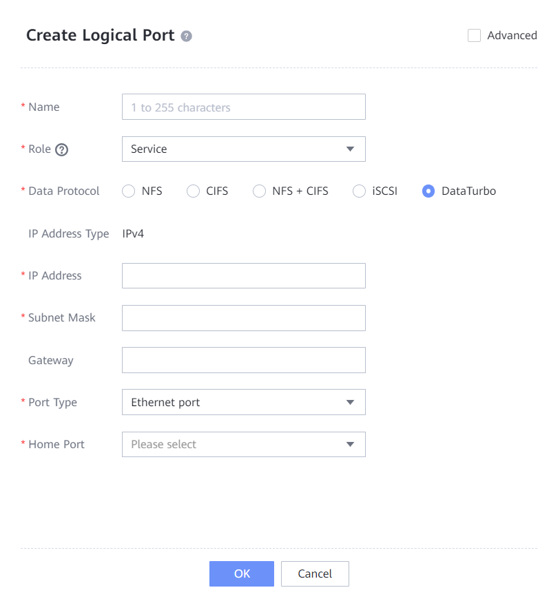
In this practice, OceanProtect X8000 has four physical ports, each of which is configured with one logical port. There are a total of four logical ports. A data protocol that contains DataTurbo is selected. In this example, DataTurbo is selected.
The following figure shows a logical port configuration example.
4.4.2.4 Creating a Host (Fibre Channel Networking)
This operation is required only when a DataTurbo over Fibre Channel network is used.
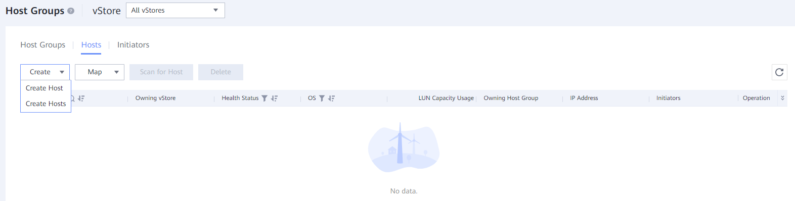
Step 1 Choose Services > Block Service > Host Groups > Hosts, click Create, and select Create Host.
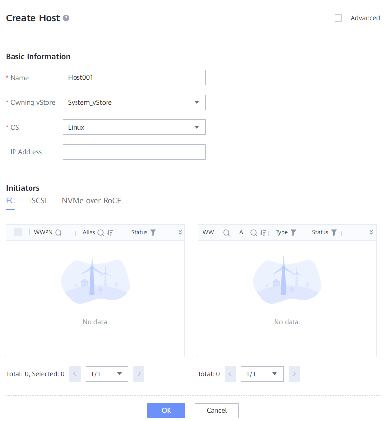
Step 2 On the Create Host page, enter the host name, add a host initiator, and click OK.
—-End
4.4.2.5 Creating Channel LUNs and Mappings (Fibre Channel Networking)
This operation is required only when a DataTurbo over Fibre Channel network is used.
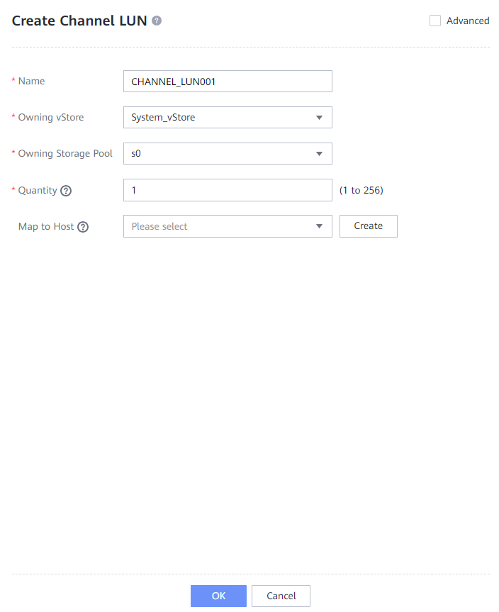
Step 1 Choose Services > Block Service > Channel LUNs, and click Create.
Step 2 On the Create Channel LUN page, enter the channel LUN name, select a host from the Map to Host field, and click OK.
—-End
4.4.2.6 Creating File Systems and a Share
Step 1 Create two file systems (100 TB each) and select the created storage pool.
Step 2 If Application Type is set to Reduction_Prioritized_Mode_enhanced, the high reduction ratio mode is used for the compression mode to save storage resources. If Application Type is set to Performance_Prioritized_Mode_enhanced, the high performance mode is used for the compression mode.
The following figure shows a file system configuration example.
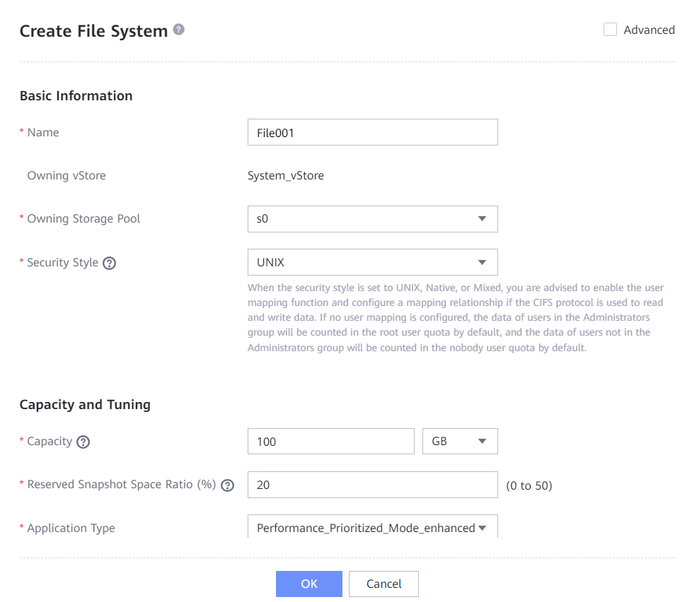
Step 3 Choose Services > vStores > System_vStore > User Management, and click Create. Set Role to vStore DataTurbo administrator, enter the username in the Username field, enter the password in Password and Confirm Password fields, and click OK.
Step 4 Choose Services > Shares > DataTurbo Shares, and click Create. Select the file system for which you want to create a share, click Add, and select the vStore DataTurbo administrator created in Step 3.
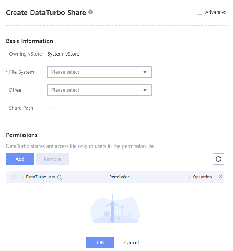
—-End
4.4.3 Interconnecting with DataTurbo
This solution uses source deduplication, which requires the DataTurbo protocol for interconnecting with the MA. A DataTurbo share is created on OceanProtect X8000. To mount the corresponding file system to the backup host using the DataTurbo protocol, you must install OceanStor DataTurbo software and configure related parameters on the MA.
DataTurbo supports TCP and Fibre Channel links. This document uses TCP links as an example.
4.4.3.1 Installation and Deployment
OceanStor DataTurbo must be installed on all Gateway Servers. For details about how to install OceanStor DataTurbo, see « Installation, Upgrade, and Uninstallation » in the OceanProtect Backup Storage 1.3.0 SourceDedupe User Guide. During the installation, select the high level.
4.4.3.2 Parameter Configuration
DataTurbo configuration includes connection establishment and file system mounting.
- Establishing connections: Connect two ports of each MA to controllers A and B of OceanProtect X8000 through two logical ports, respectively. That is, each backup host is connected to the back-end storage through 2 x 10GE.
- Mounting file systems: Create two file systems on OceanProtect X8000 and mount them to the two backup hosts, respectively.
Establishing Connection
Step 1 Run the dataturbo create storage_object storage_name=name ip_list=IP address command (name indicates the user-defined storage name, and IP address indicates the IP address of the logical port created on OceanProtect X8000) to establish connection between OceanStor DataTurbo and OceanProtect X8000. Enter the username and password of the created DataTurbo user as prompted.
In this example, the storage name is storage1 and the logical port IP address is 10.10.10.10.
[root@host192 mnt]# dataturbo create storage_object storage_name=storage1 ip_list=10.10.10.10
Please input username:
dataturbo_user
Please input password:
**********
Create storage object successfully.
Step 2 Run the dataturbo show storage_object command to check whether the connection is successful.
If the following information is displayed and Status is Normal, the connection is successful.
[root@host192 mnt]# dataturbo show storage_object
Storage Name: huawei
User : dataturbo_user
Ips : 10.10.10.10
IpPair :
ID Local Address Remote Address Status
—————————————————————
1 10.10.10.101 10.10.10.10 Normal
Step 3 After the connection is established, log in to DeviceManager and choose Services > DataTurbo Clients to view the backup server information.
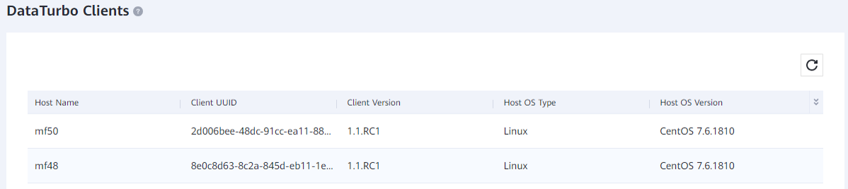
—-End
Mounting a File System
Step 1 Run the dataturbo mount storage_object storage_name=name filesystem_name=/fsname mount_dir=/mnt/test command to mount a file system created on the backup storage to a specified mount point.
name indicates the user-defined storage name, and fsname indicates the name of the file system or dtree created on OceanProtect X8000.
In the following example, the storage name is storage1, the file system name is testfile, and the mount point is /mnt/test.
[root@host192 mnt]# dataturbo mount storage_object storage_name=storage1 filesystem_name=/File01/Dtree1 mount_dir=/mnt/test
Command executed successfully.
Step 2 Run the df -h command to check whether the mounting is successful.
Filesystem Size Used Avail Use% Mounted on
/dev/mapper/centos-root 45G 24G 21G 55% /
devtmpfs 4.8G 0 4.8G 0% /dev
tmpfs 4.9G 8.0K 4.9G 1% /dev/shm
tmpfs 4.9G 9.3M 4.8G 1% /run
tmpfs 4.9G 0 4.9G 0% /sys/fs/cgroup
/dev/sda1 1014M 179M 836M 18% /boot
tmpfs 984M 0 984M 0% /run/user/0
/File01/Dtree1 80G 0 80G 0% /mnt/test
—-End
4.4.4. Installing Data Protector
In this best practice, Data Protector 11.03 is used. The Data Protector software must be installed on the Data Protector Cell Manager and MA. For details about how to install the Data Protector software and configure the Installation Server, see the official documents of Data Protector.
4.4.5 Configuring the Data Protector Backup Environment (VMware)
4.4.5.1 Configuring a Virtual Environment Integration Client
The virtual environment integration client described in this section is used in Data Protector backup and restoration service processes. It is installed at the production system side and does not connect to OceanProtect.
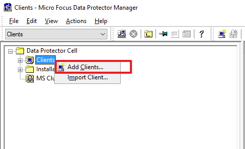
Step 1 On the Clients page, right-click Clients and select Add Clients to create a client.
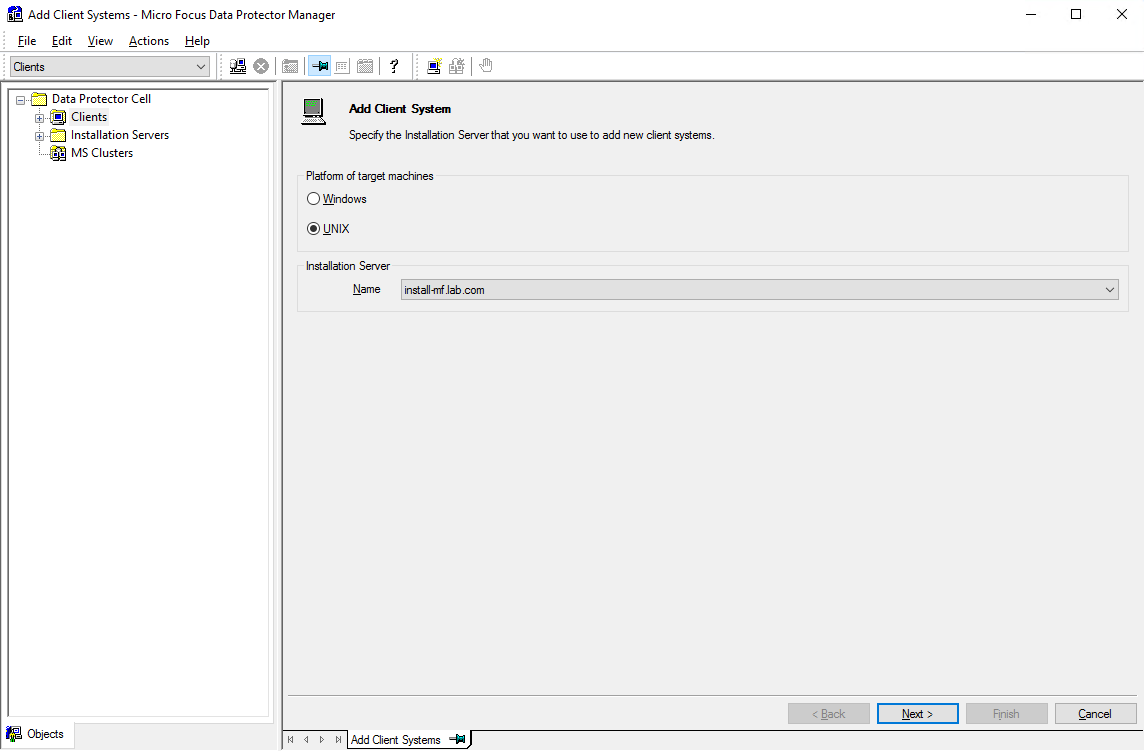
Step 2 Select a platform and an Installation Server based on the OS of the client that needs component installation pushing. Then, click Next.
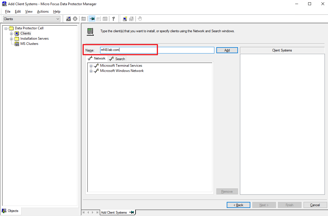
Step 3 Enter the domain name of the client that needs component installation in the Name field, click Add to add it to the list on the right, and then click Next.
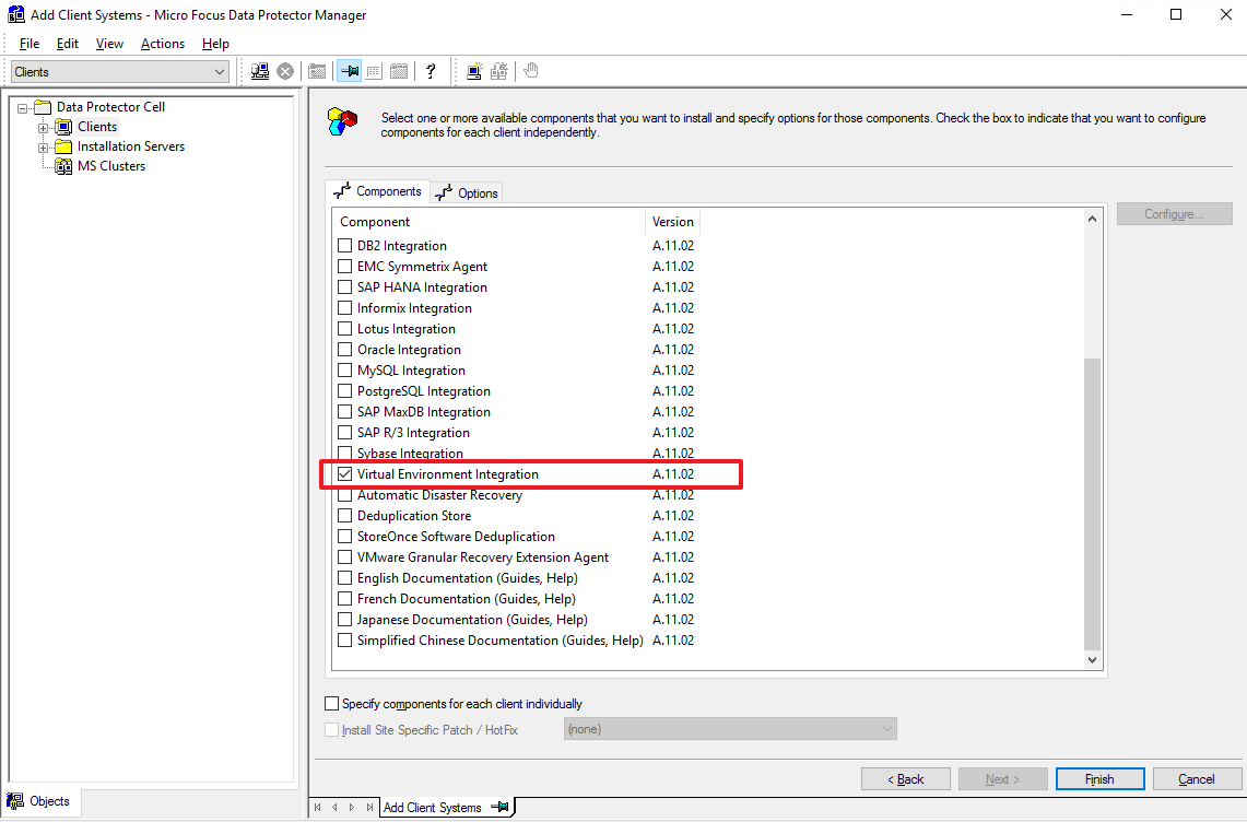
Step 4 Select Virtual Environment Integration from the component list and click Finish to start pushing.
Step 5 During the installation, you need to provide the system username and password of the client. If an addition failure message is displayed, perform operations by referring to official guides of Data Protector.
4.4.5.2 Importing a VMware Client
The VMware client described in this section is the backup source, that is, the production system to which the VM to be backed up belongs.
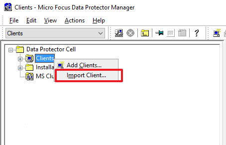
Step 1 On the Clients page, right-click Clients and select Import Client to import a client.
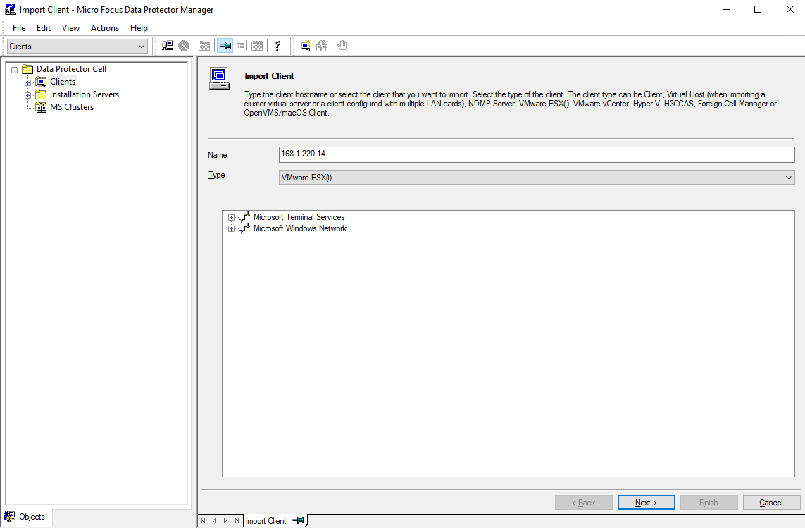
Step 2 On the Import Client page, enter a name, and set Type to VMware ESX(i) or VMware vCenter. VMware ESX(i) is used as an example here. Then, click Next.
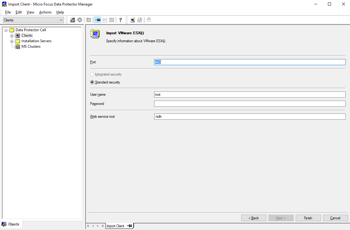
Step 3 Enter the username and password for the ESXi host, and click Finish.
—-End
4.4.5.3 Configuring an MA
The MA client described in this section is the backup media server used to connect to OceanProtect.
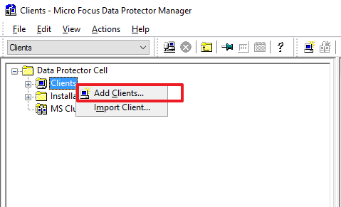
Step 1 On the Clients page, right-click Clients and select Add Clients to create a client.
Step 2 Select a platform and an Installation Server based on the OS of the client that needs component installation pushing. Then, click Next.
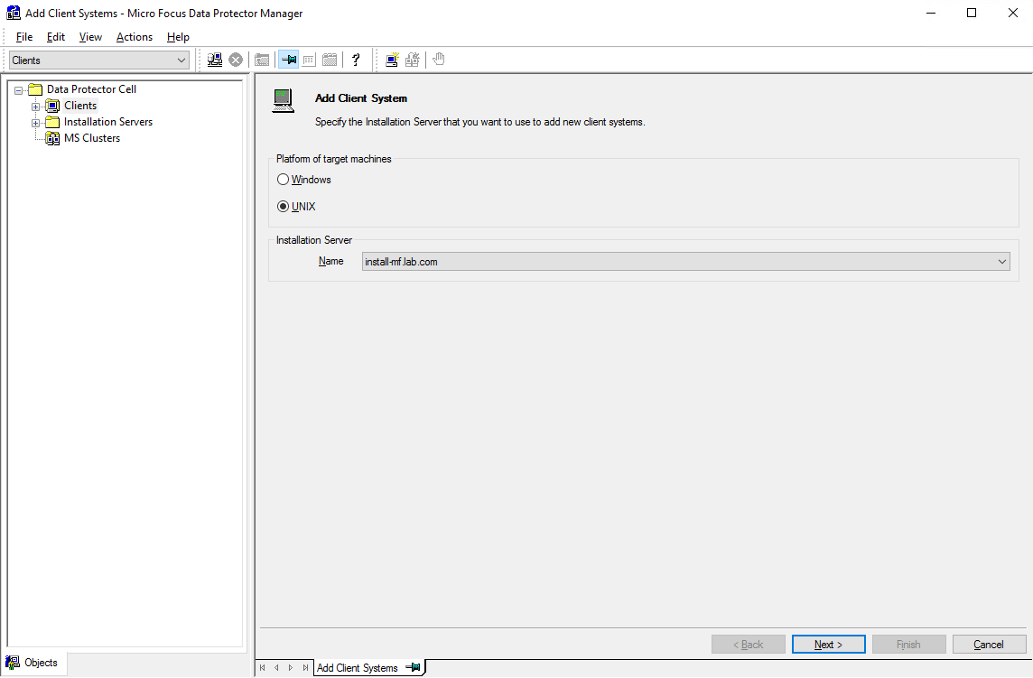
Step 3 Enter the domain name of the client that needs component installation in the Name field, click Add to add it to the list on the right, and then click Next.
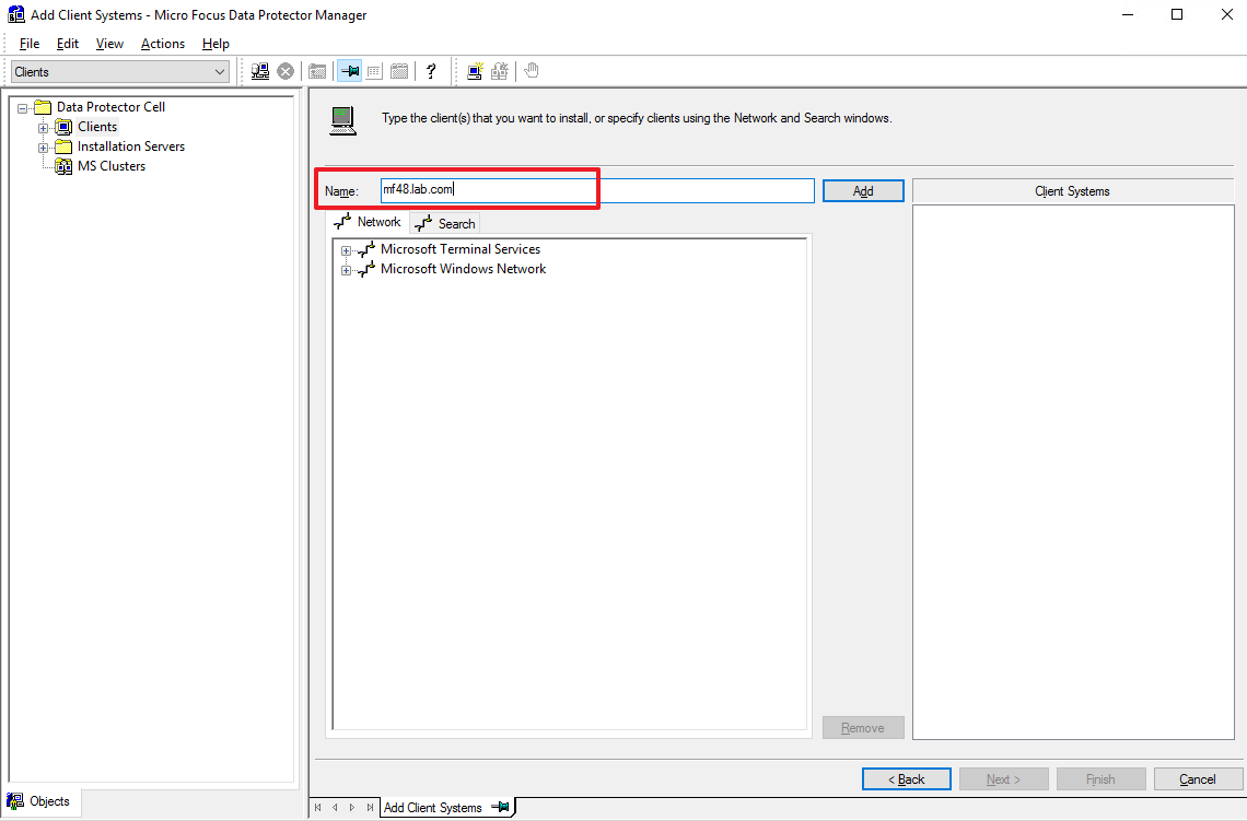
Step 4 Select General Media Agent from the component list and click Finish to start pushing.
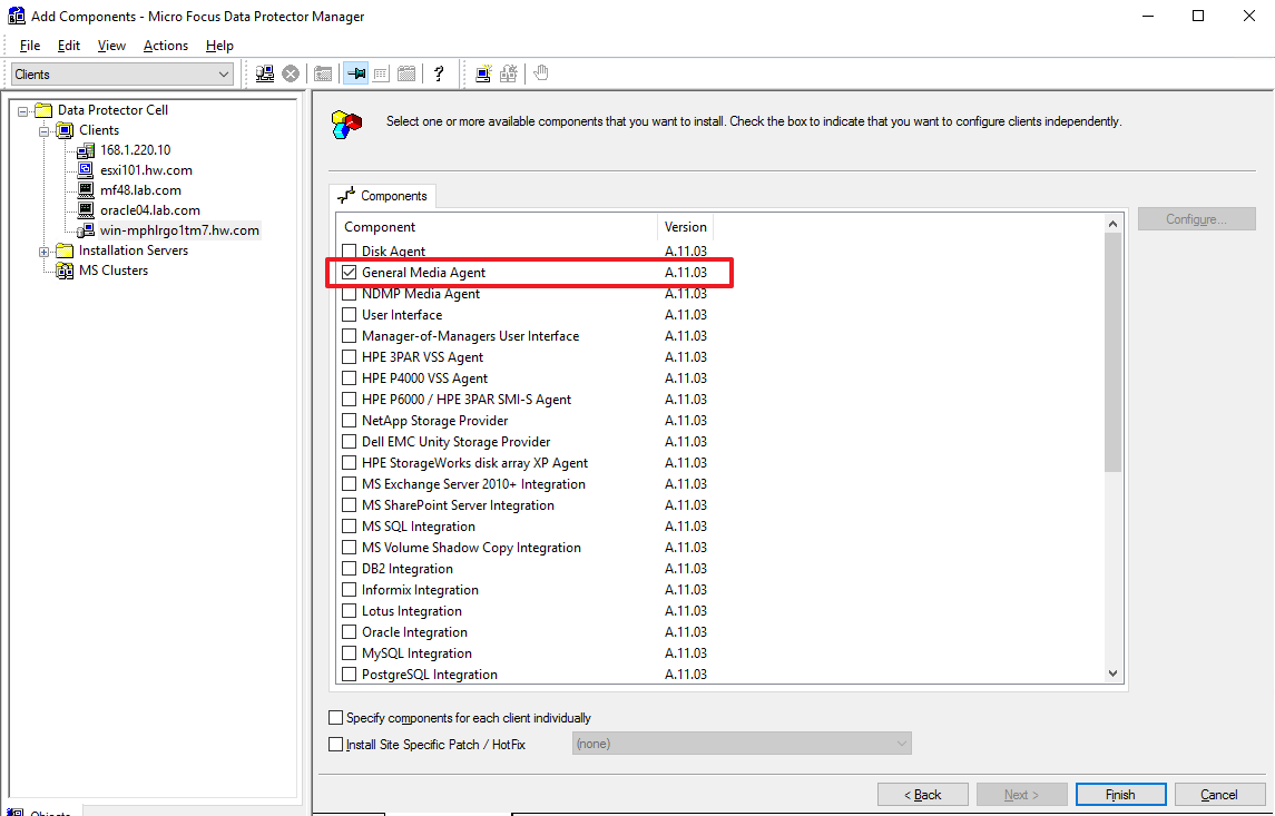
4.4.5.4 Configuring a Device
Step 1 Go to the Devices & Meida page, right-click Devices, and select Add Device to create a device.
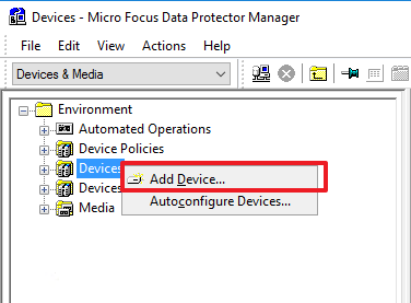
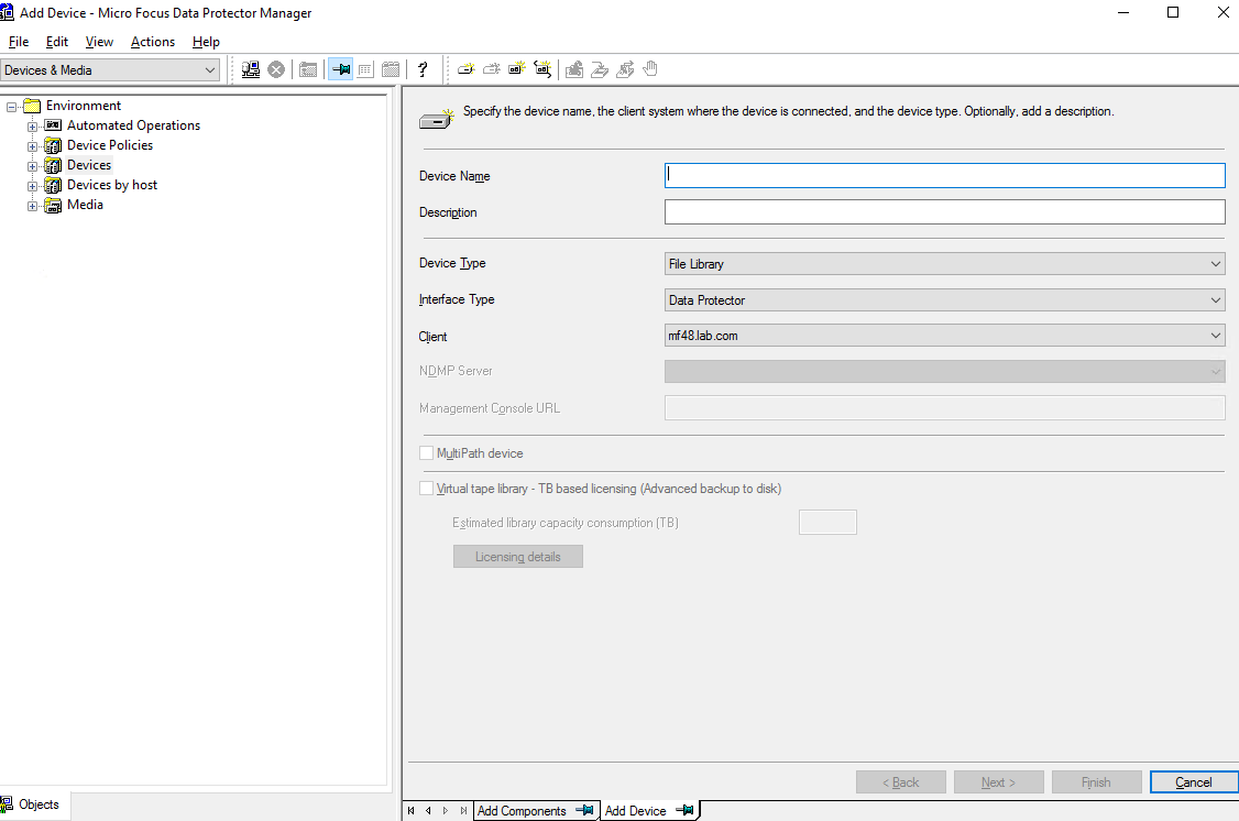
Step 2 On the Add Device page, enter a device name, set Device Type to File Library, set Interface Type to Data Protector, and select the client where the General Media Agent component has been installed.
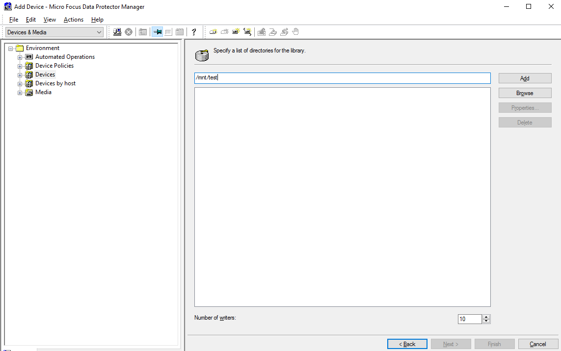
Step 3 In the first field, enter the directory to which the file system is mounted on the backup media server. Click Add to add it to the second field. Set Number of writers as needed. In this example, Number of writers to set to 10. Then, click Next.
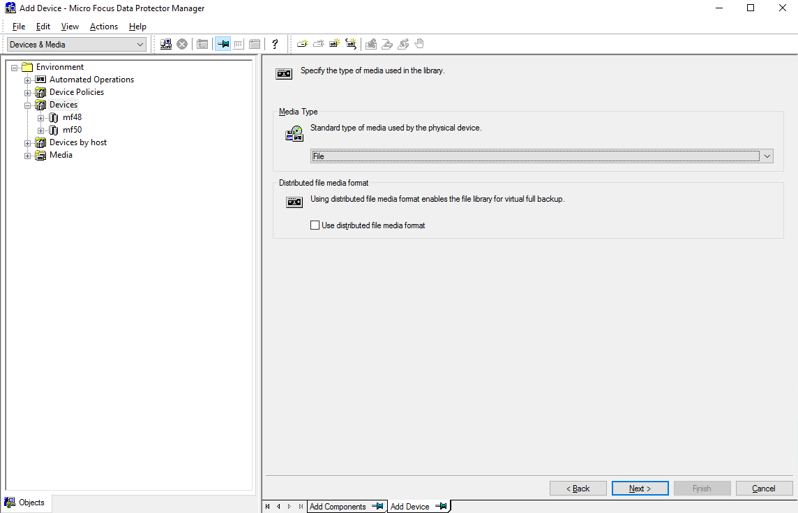
Step 4 Retain default settings and click Next.
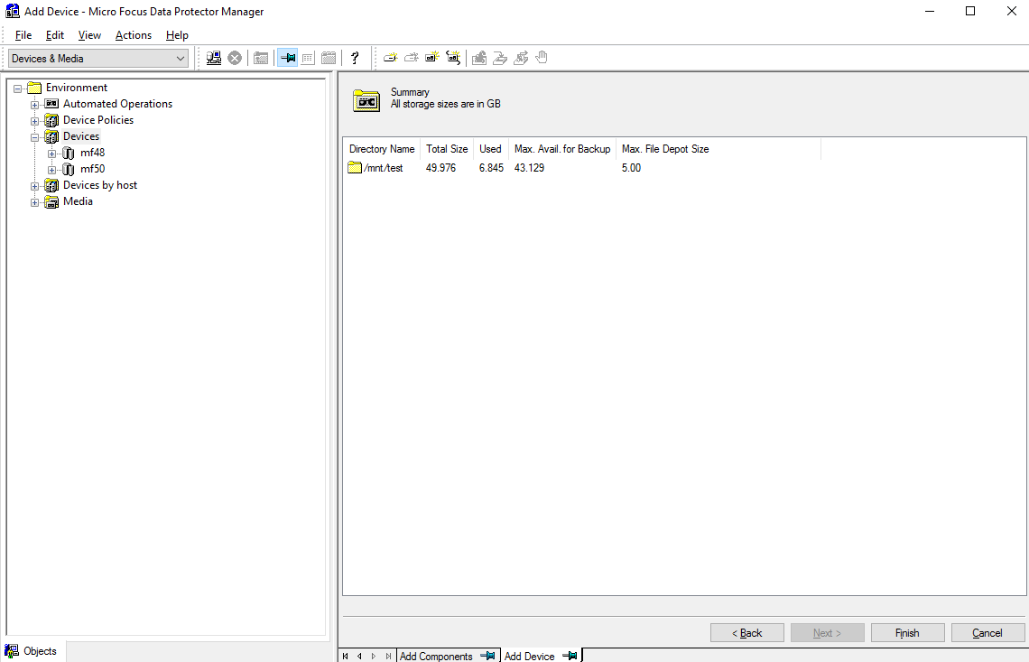
Step 5 Click Finish.
4.4.5.5 Configuring a Backup Job
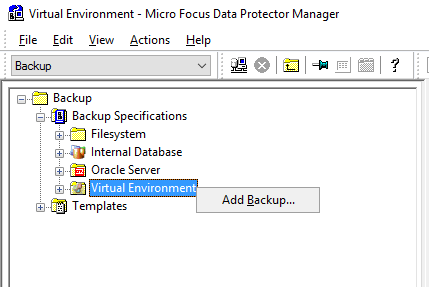
Step 1 Select Backup Specifications, right-click Virtual Environment, and click Add Backup to create a backup job.
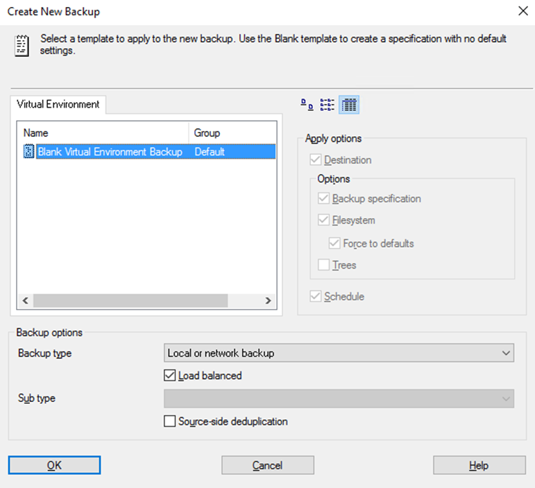
Step 2 On the Create New Backup page, select Blank Virtual Environment Backup. Set Backup type to Local or network backup, select Load balanced, deselect Source-side deduplication, and click OK.
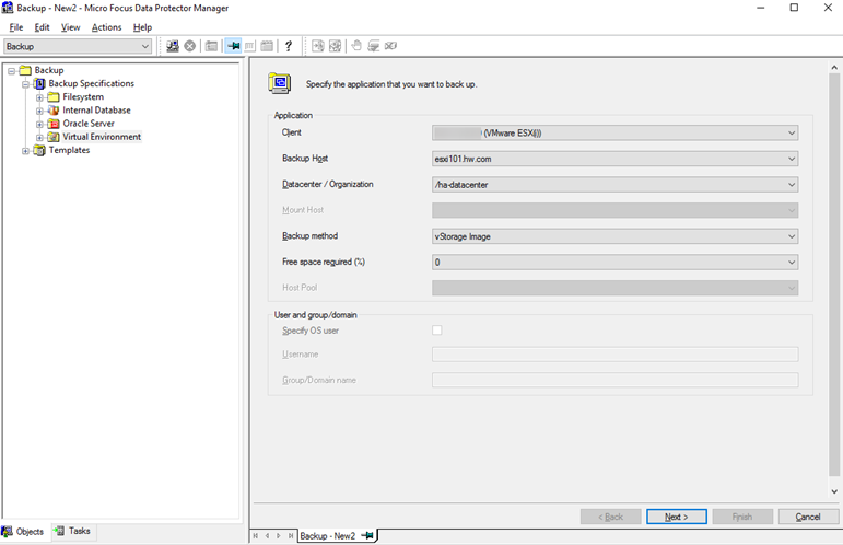
Step 3 Set Client to the ESXi host or vCenter configured in 4.4.5.2 Importing a VMware Client, set Backup Host to the client configured in 4.4.5.1 Configuring a Virtual Environment Integration Client, and set other parameters based on the actual situation. Click Next.
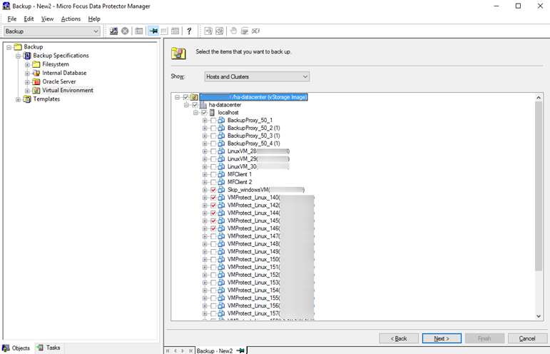
Step 4 Select the VMs to be backed up and click Next.
Step 5 Select the device created in 4.4.5.4 Configuring a Device for backup, and click Next.
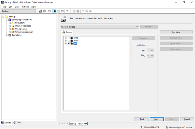
Step 6 Retain default settings and click Next.
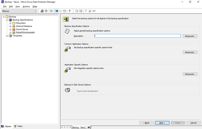
Step 7 Click Add to add a schedule based on the actual backup plan and click Next.
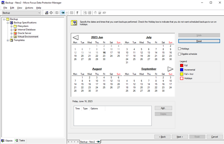
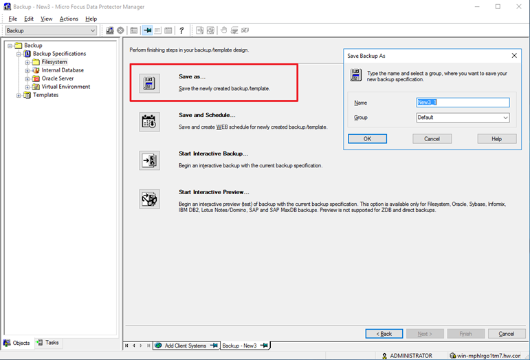
Step 8 Click Save as… to name and save the backup job.
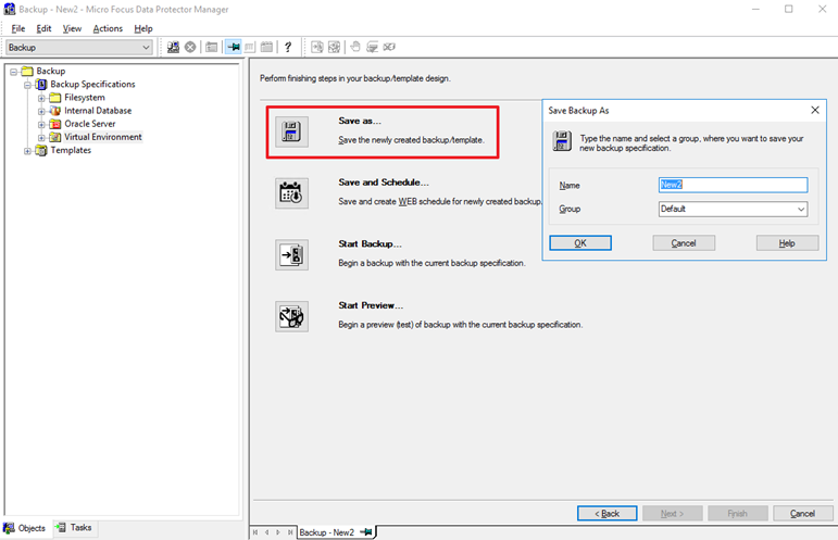
—-End
4.4.6 Configuring the Data Protector Backup Environment (File System)
4.4.6.1 Configuring a DA Client
The DA client described in this section is used in Data Protector backup and restoration service processes. It is installed on the file system server to be backed up and does not connect to OceanProtect.
Step 1 On the Clients page, right-click Clients and select Add Clients to create a client.
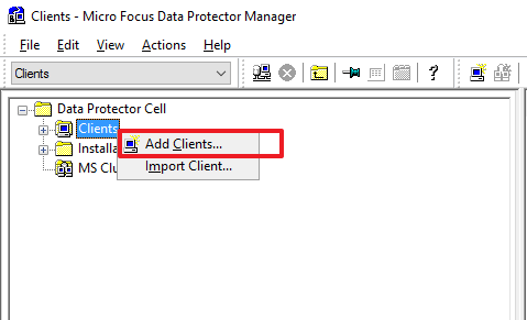
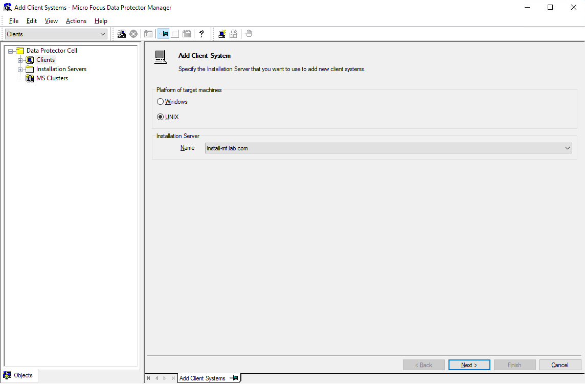
Step 2 Select a platform and an Installation Server based on the OS of the client that needs component installation pushing. Then, click Next.
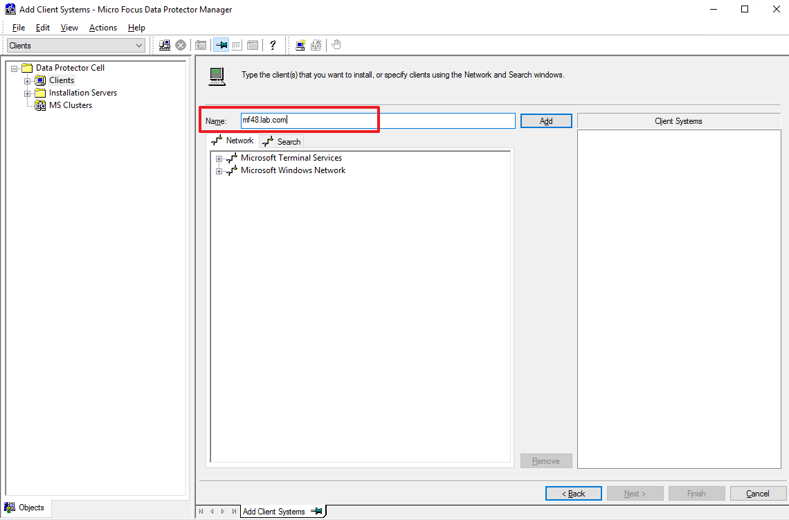
Step 3 Enter the domain name of the client that needs component installation in the Name field, click Add to add it to the list on the right, and then click Next.
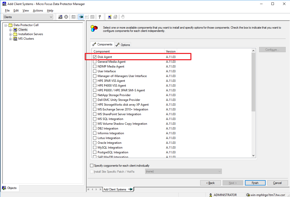
Step 4 Select Disk Agent from the component list and click Finish to start pushing.
Step 5 During the installation, you need to provide the system username and password of the client. If an addition failure message is displayed, perform operations by referring to official guides of Data Protector.
—-End
4.4.6.2 Configuring an MA
The MA client described in this section is the backup media server used to connect to OceanProtect.
Step 1 On the Clients page, right-click Clients and select Add Clients to create a client.
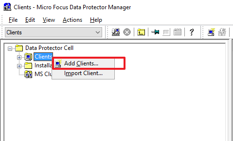
Step 2 Select a platform and an Installation Server based on the OS of the client that needs component installation pushing. Then, click Next.
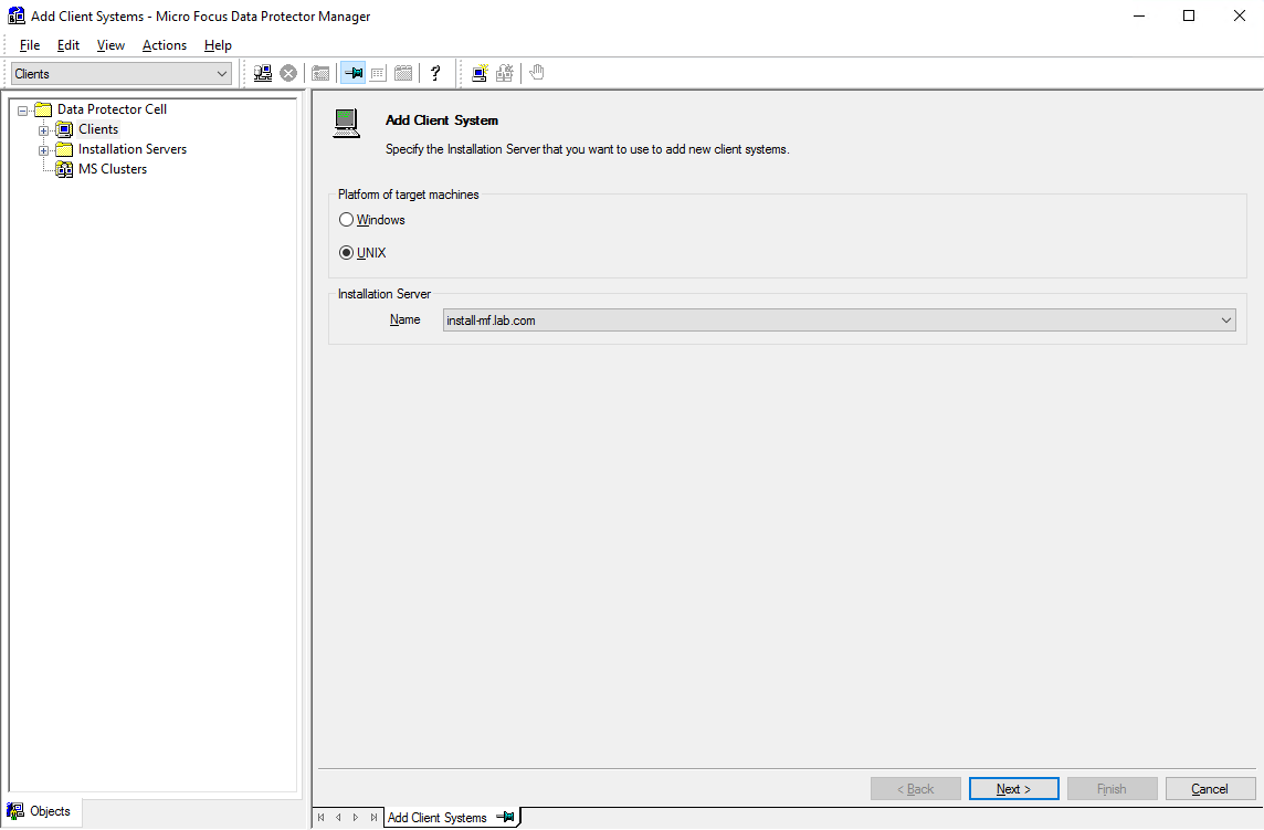
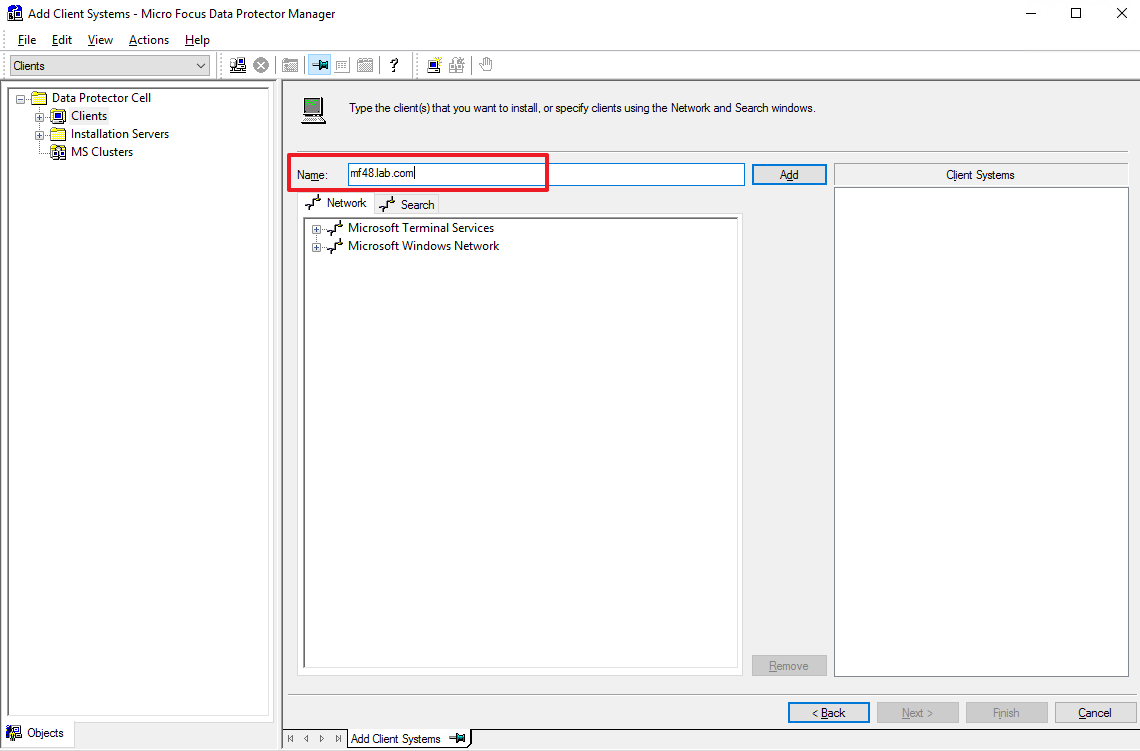
Step 3 Enter the domain name of the client that needs component installation in the Name field, click Add to add it to the list on the right, and then click Next.
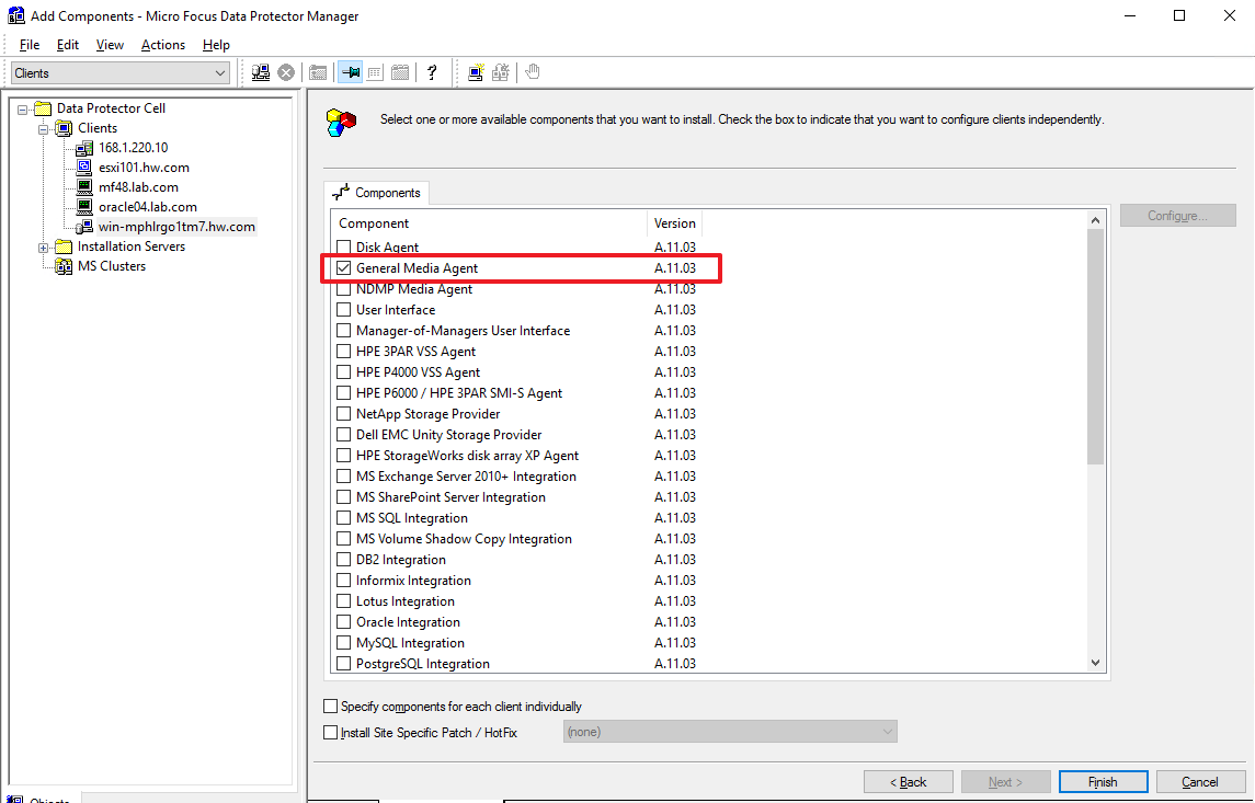
Step 4 Select General Media Agent from the component list and click Finish to start pushing.
—-End
4.4.6.3 Configuring a Device
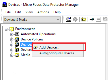
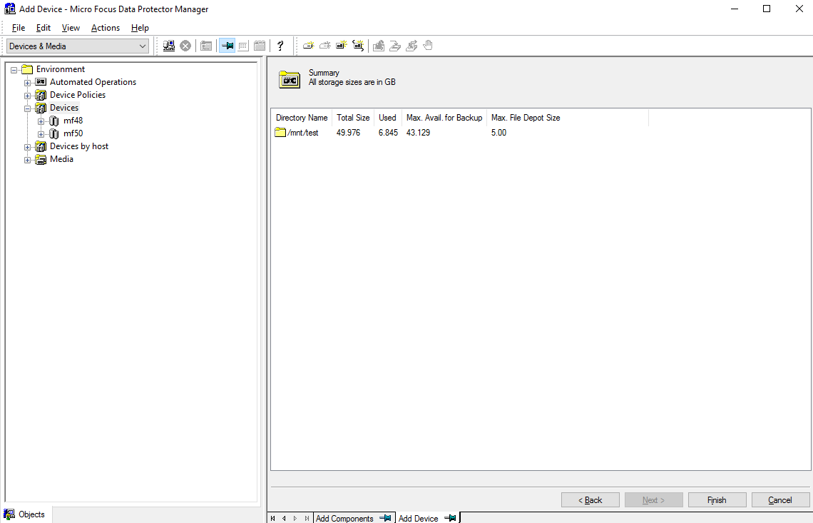
Step 1 Go to the Devices & Meida page, right-click Devices, and select Add Device to create a device.
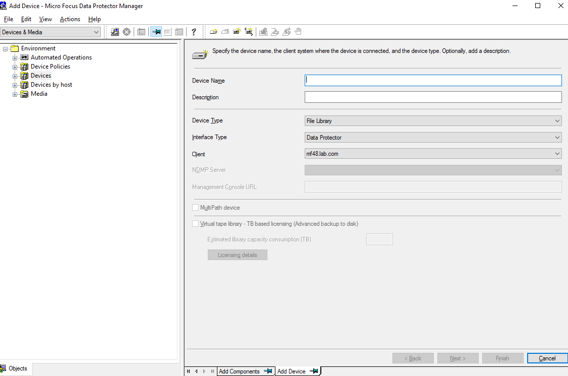
Step 2 On the Add Device page, enter a device name, set Device Type to File Library, set Interface Type to Data Protector, and select the client where the General Media Agent component has been installed.
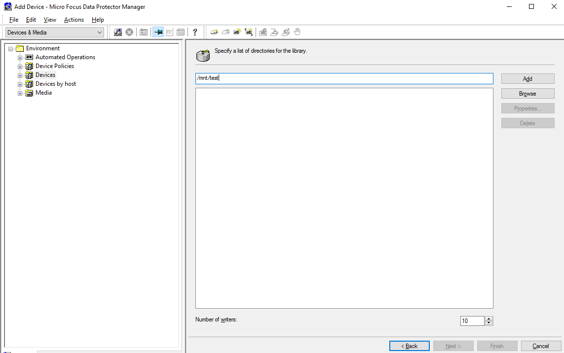
Step 3 In the first field, enter the directory to which the file system is mounted on the backup media server. Click Add to add it to the second field. Set Number of writers as needed. In this example, Number of writers to set to 10. Then, click Next.
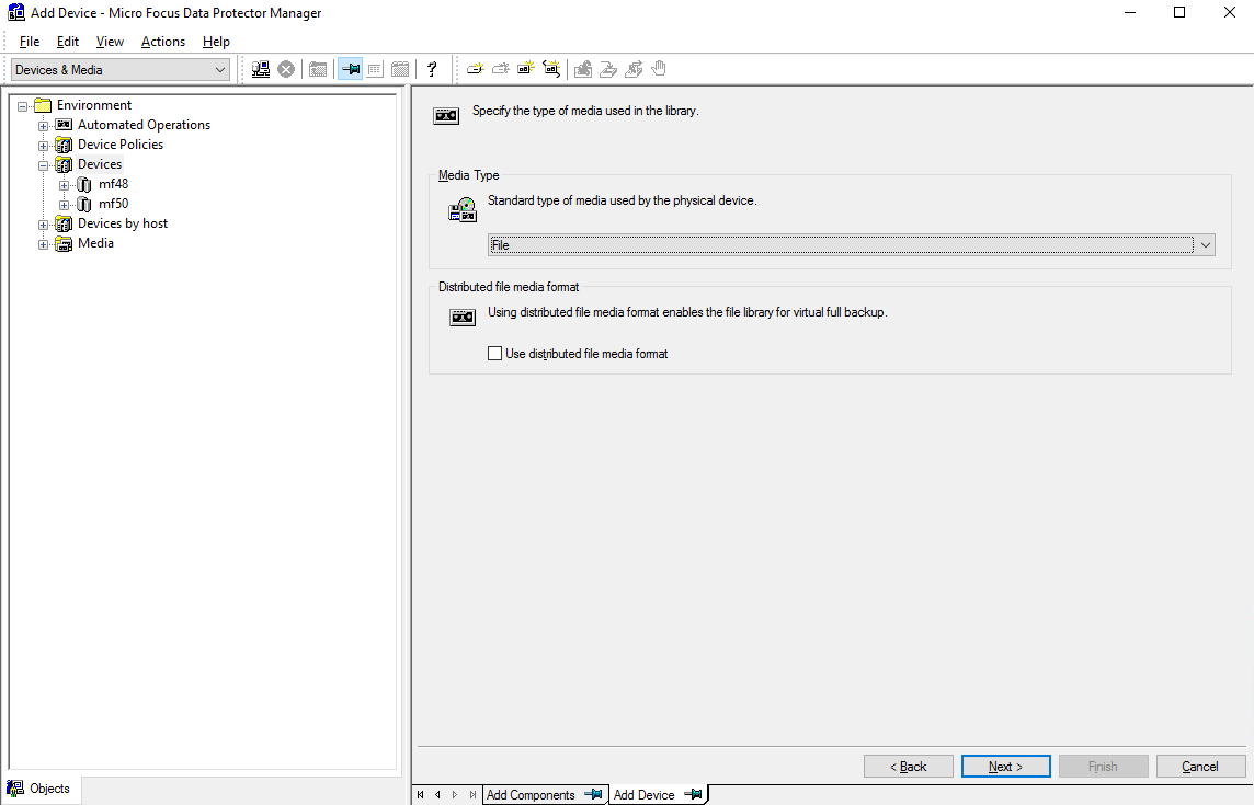
Step 4 Retain default settings and click Next.
Step 5 Click Finish.
—-End
4.4.6.4 Configuring a Backup Job
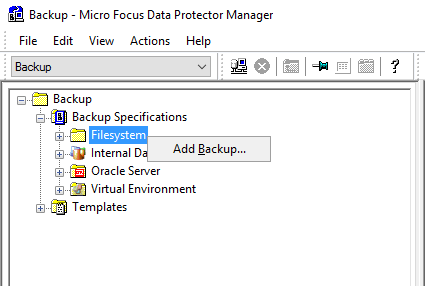
Step 1 Select Backup Specifications, right-click Filesystem, and click Add Backup to create a backup job.
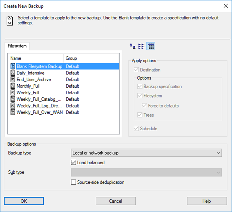
Step 2 On the Create New Backup page, select an object from the Filesystem list as needed. In this example, select Blank Filesystem Backup. Set Backup type to Local or network backup, select Load balanced, deselect Source-side deduplication, and click OK.
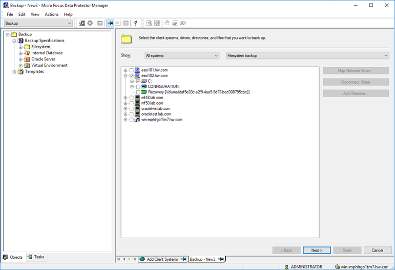
Step 3 Select the DA client configured in 4.4.6.1 Configuring a DA Client, select the file directory to be backed up, and click Next.
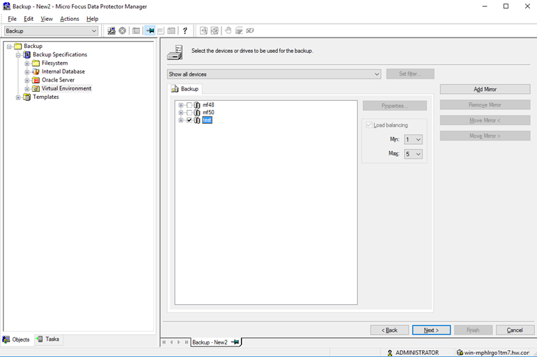
Step 4 Select the device created in 4.4.5.4 Configuring a Device for backup, and click Next.
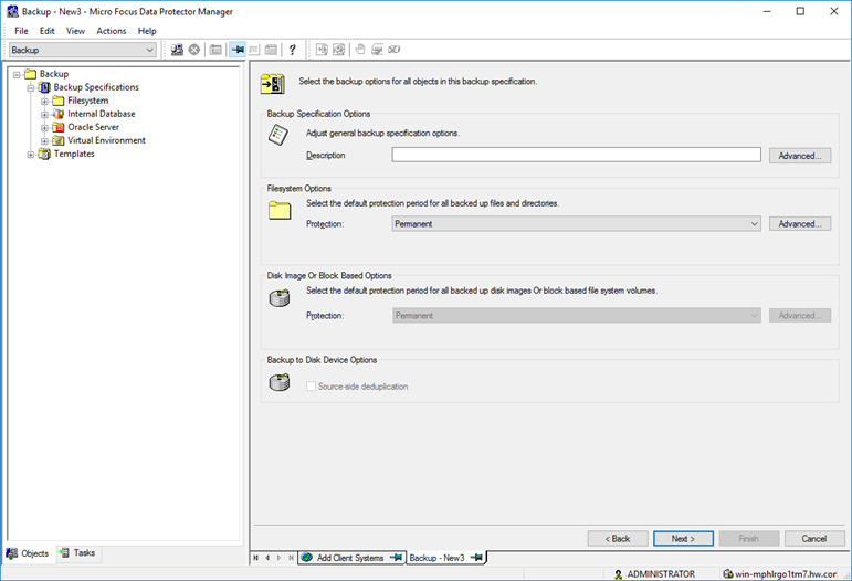
Step 5 In the Filesystem Options area, select a mode as needed. In this example, use default parameter settings. Then, click Next.
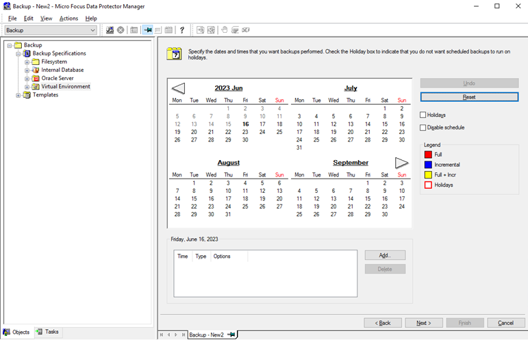
Step 6 Click Add to add a schedule based on the actual backup plan and click Next.
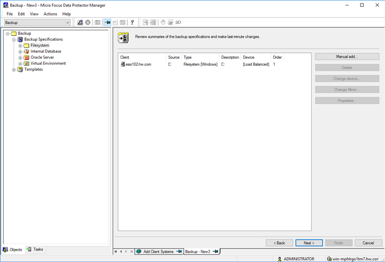
Step 7 On the summary page, make no change and click Next.
Step 8 Click Save as… to name and save the backup job.
—-End
4.4.7 Executing Backup
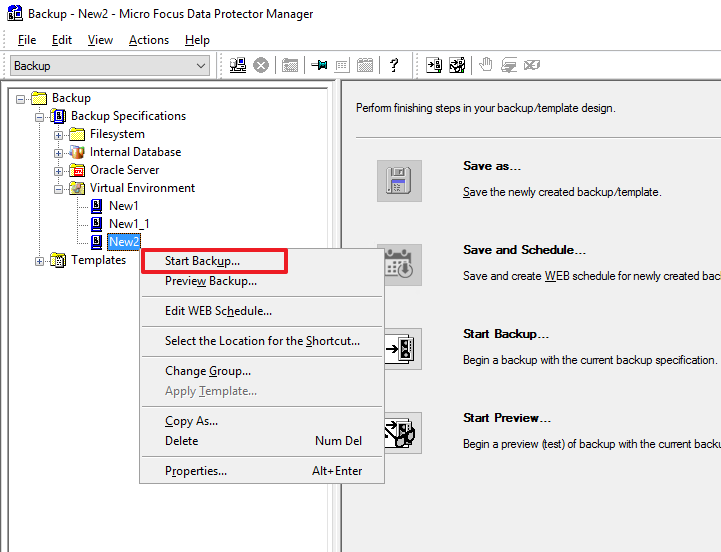
Step 1 On the Backup page, expand the item based on the type of the application to be backed up. For VMware backup in this example, right-click the backup task and select Start Backup.
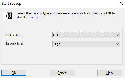
Step 2 In this example, select Full for Backup type and High for Network load. Then, click OK to start backup.
—-End
4.4.8 Executing Restoration
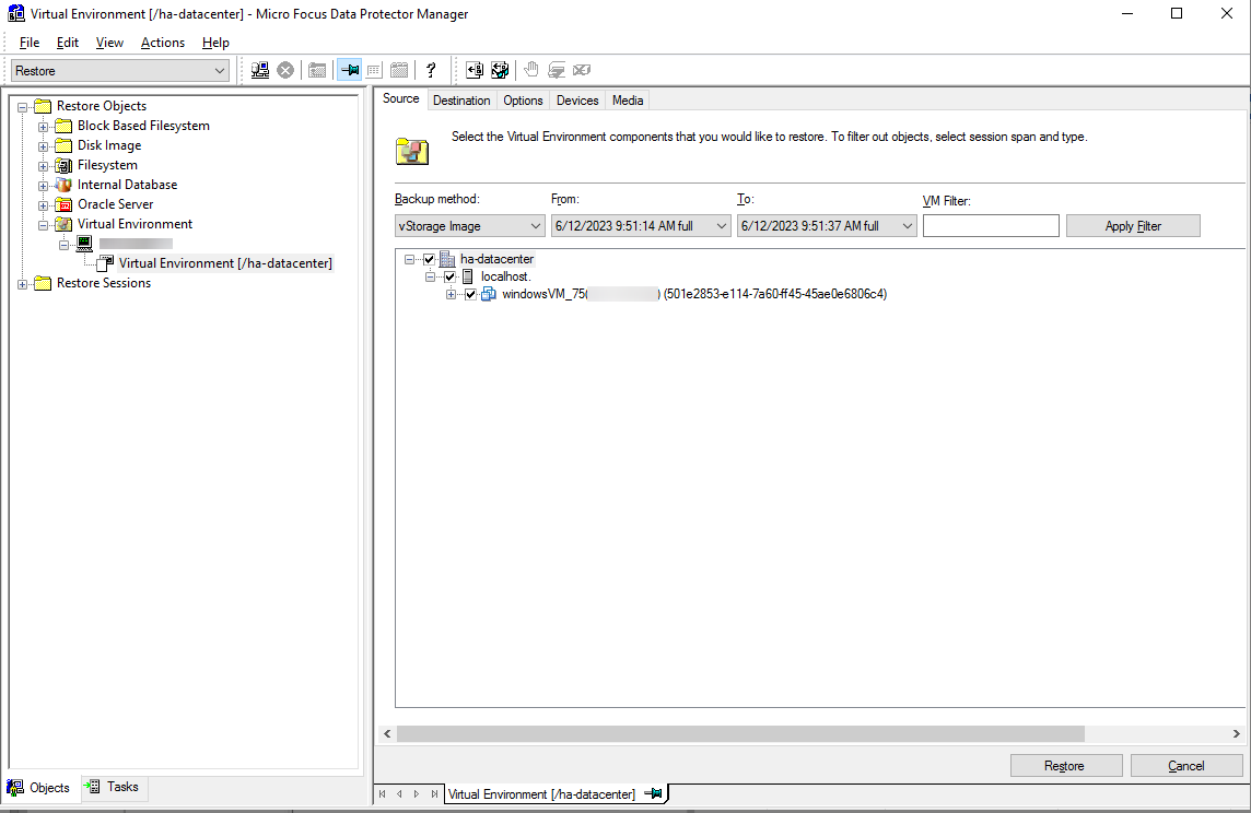
Step 1 On the Restore page, select an existing backup copy and select the VM to be restored on the Source tab.
Step 2 On the Destination tab, set Backup host and Restore client (target ESXi host of the restoration). In this example, perform restoration to the original location. Retain default settings.

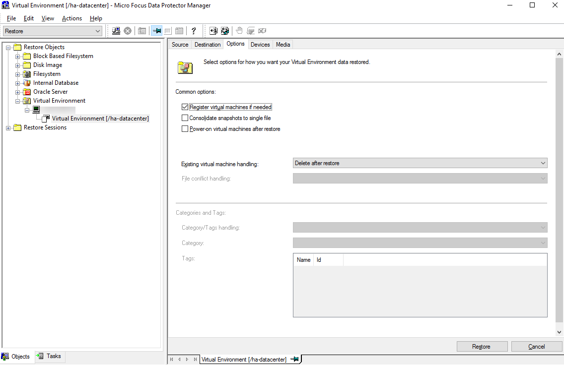
Step 3 On the Options tab, perform common restoration settings. Retain default settings on the Devices and Media tabs. Then, click Restore.
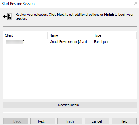
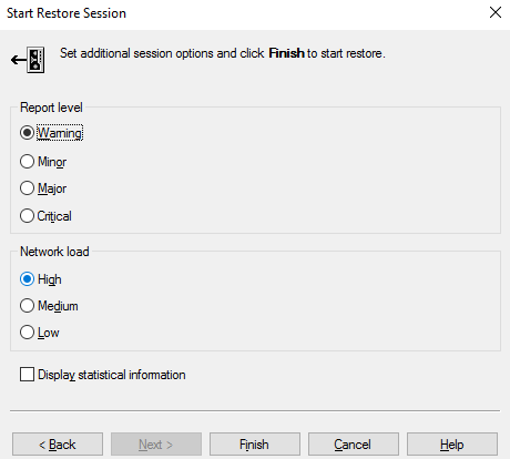
Step 4 On the Start Restore Session page, click Next to change report and network load levels. In this example, make no change and click Finish to start restoration.
4.5 S3-based Backup and Restoration Configuration Example
4.5.1 Solution Networking
Figure 4-5 shows a networking example of the VMware backup solution in this practice.
Figure 4-5 Networking diagram of the VMware backup solution using OceanProtect E8000 and Data Protector S3
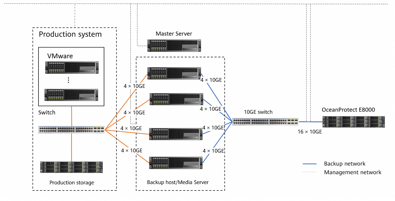

The networking diagram shown in Figure 4-5 is for reference only. For details about the cable connections between the OceanProtect E8000 controller enclosures and application servers or disk enclosures, and between the controller enclosures, see « Cabinet Layout and Connection Planning » in the OceanProtect E8000 Backup Storage V200R001 Hardware Installation Guide.
The OceanProtect Backup Storage uses the S3 protocol to integrate Data Protector for VMware backup. The networking is described as follows:
- VMware: In this practice, multiple ESXi hosts are deployed and connected to one production storage device. TCP links are used for connection.
- Master Server: deployed on a VM and connected to all backup hosts and Media Servers over the management network.
- Backup hosts and Media Servers:
- In this networking, the SAN transmission mode is used. Backup hosts and Media Servers are co-deployed and connected to the VMware production storage device through a switch.
- Each backup host uses four 10GE links to form a bond and connects to the OceanProtect Backup Storage through a switch.
- The OceanProtect Backup Storage connects to the switch over 16 × 10GE links.
4.5.2 Storage Configuration
This section describes how to use the OceanProtect Backup Storage to create a bucket that can be accessed by external hosts through the S3 protocol, and introduces the recommended network load balancing solution.
4.5.2.1 Network Configuration
This section describes how to create an object service logical port and use the DNS zone. The logical port can be directly accessed externally through an IP address. It can also be added to a DNS zone to implement load balancing among multiple logical ports through domain name resolution.
If you plan to directly use the logical port IP address for access, refer to steps 4 and 5 and skip the DNS configuration.
Table 4-3 Comparison between the DNS solution and the IP address solution
Type | DNS Solution | IP Address Solution |
|---|---|---|
External use | Load balancing among all physical ports can be implemented by using only the configured domain name of the DNS zone. | The IP address of each physical port or bond port must be provided externally. |
External dependency | The DNS domain name is resolved by using the domain name resolution service configured on the host. | None. The host only needs to communicate with the IP address. |
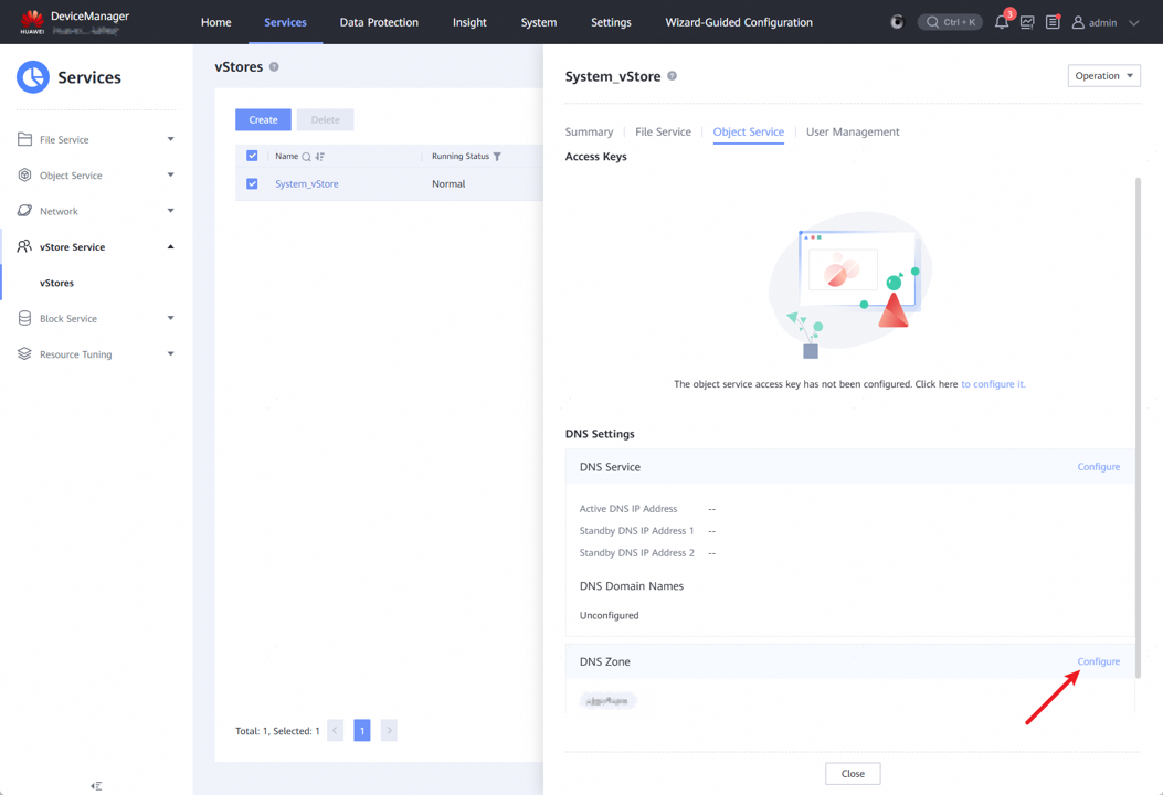
Step 1 Configure a DNS zone. Choose Services > vStore Service > vStores. Choose System_vStore > Object Service, and click Configure in the DNS Zone area.
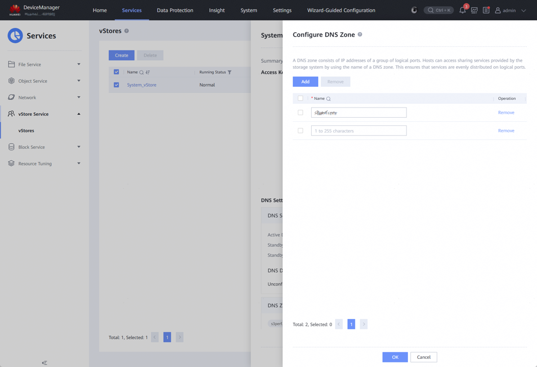
Step 2 Click Add, enter a custom domain name (for example, S3test.com), and click OK.
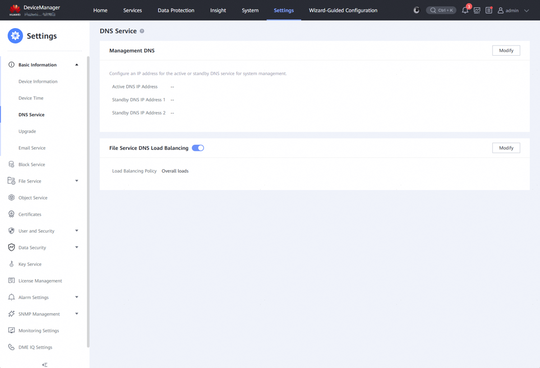
Step 3 Enable File Service DNS Load Balancing. Choose Settings > Basic Information > DNS Service and enable File Service DNS Load Balancing.
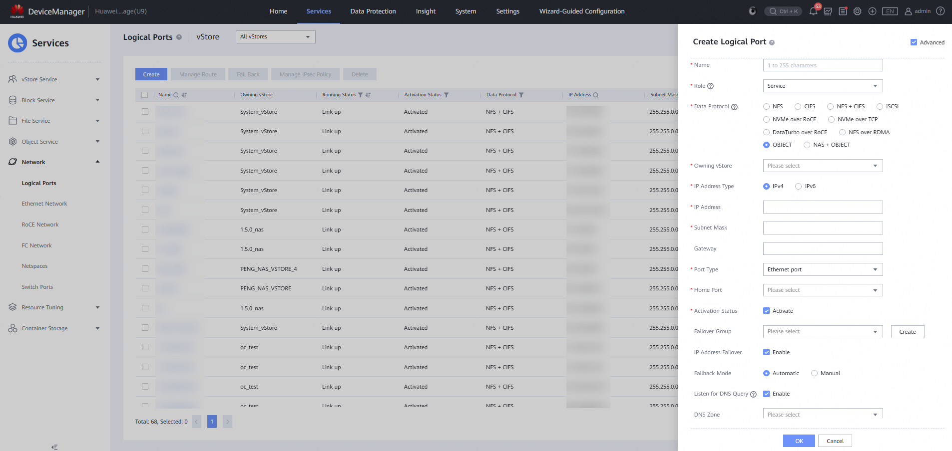
Step 4 Create a logical port. Choose Services > Network > Logical Ports and click Create.
Step 5 Configure the logical port. Select Advanced in the upper right corner, customize Name, set Role to Service, set Data Protocol to OBJECT, set IP Address, Subnet Mask, and Home Port as planned, and set DNS Zone to the DNS zone configured in Step 1.
Select any logical port from the logical ports added to the same DNS zone, and select Listen for DNS Query. Do not select this option for other logical ports.
Modify other options as required or retain the default values.

To use a DNS domain name, the host must be able to resolve it. Add the IP address of the listening port to the DNS service information of the backup host.
For example, if you select the logical port with IP address 192.168.10.100 from those created in step 5 and select Listen for DNS Query, you need to add this IP address to the DNS service information of the host.
Windows:
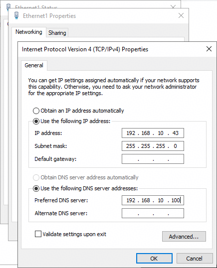
If a DNS server has been configured for Preferred DNS server, add the IP address to Alternate DNS server.
Linux:
Add the line nameserver 192.168.10.100 to the /etc/resolv.conf file.
4.5.2.2 Bucket Configuration
This section describes how to configure a bucket on the OceanProtect Backup Storage.
Step 1 Log in to the OceanProtect Backup Storage background using the CLI, enter the developer mode, and run the change service object region_enable=disable command. If this operation is not performed, the Data Protector software cannot detect the S3 bucket during scan.
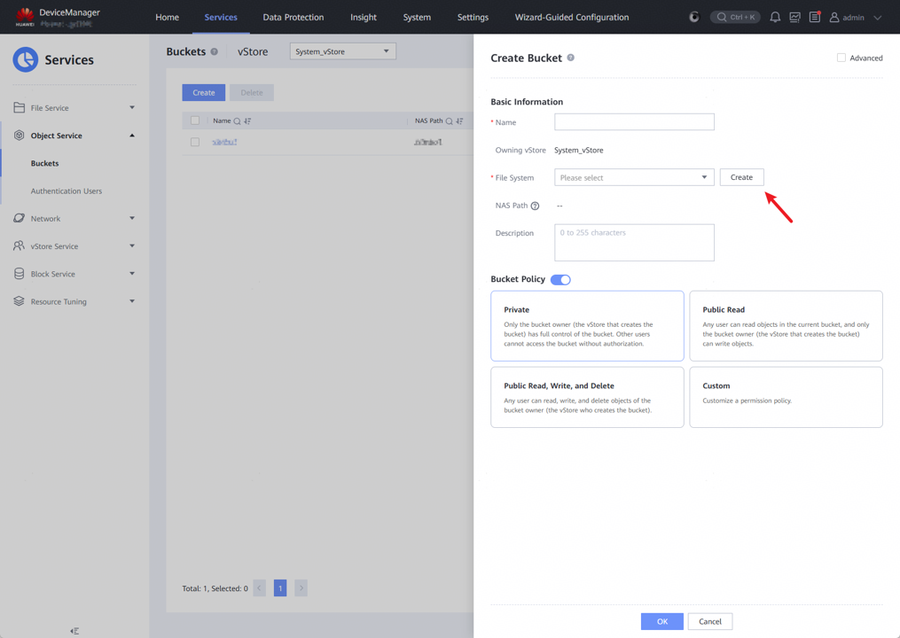
Step 2 Create a bucket. Choose Services > Object Service > Buckets and click Create.
Step 3 Enter a custom name, enable Bucket Policy, select Private, and click Create in the File System area.
Step 4 Enter a custom name, set Security Style to Mixed, set Capacity as planned, disable Shares of all types, and retain the default values for other parameters.
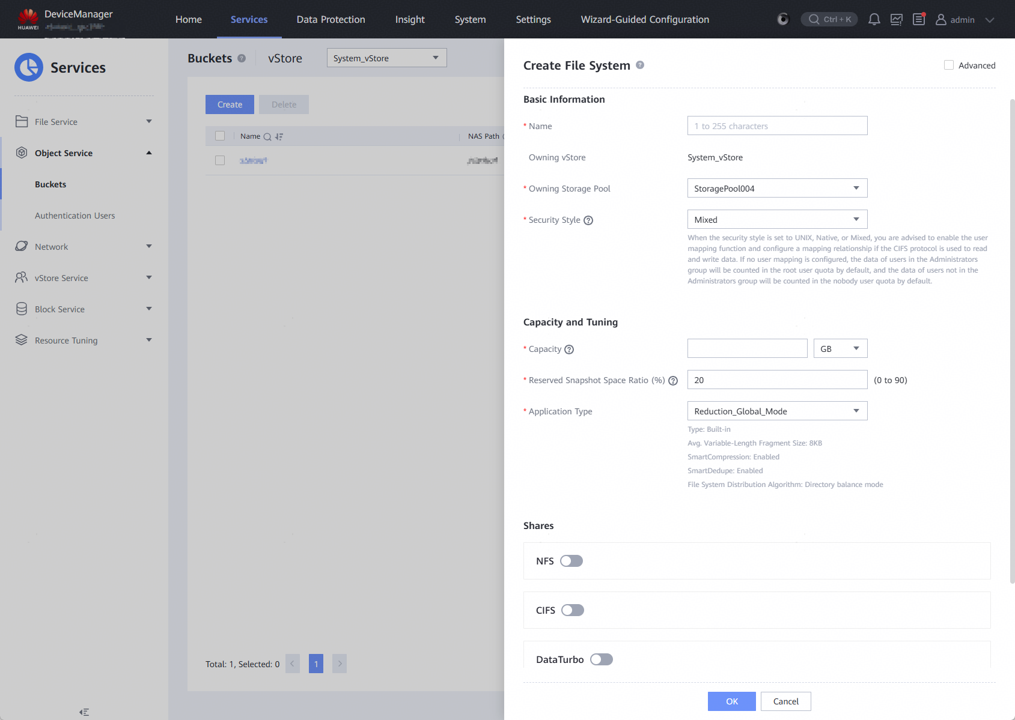
Step 5 Click OK on the Create File System and Create Bucket tab pages in sequence to complete bucket creation.
4.5.2.3 Object User Configuration
Step 1 Choose Services > Object Service > Authentication Users and click Create.
Step 2 Enter a custom name and set User Type to Local authentication user.
Step 3 In the Access Keys area, select Automatic or Manual as required. If you select Automatic, a file containing the randomly generated access key (AK) and secret key (SK) will be downloaded. If you select Manual, you need to customize the AK and SK.
Step 4 Click Create under User Permission Policies.
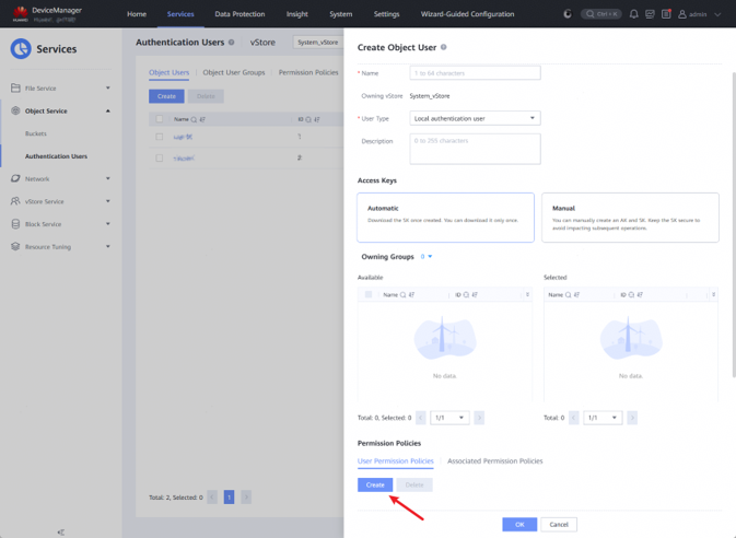
Step 5 Enter a custom name. In the Permission Configuration 1 area under Edit Permission Policy, select Allow under Effect, select Include and All under Action, and select Include and All under Resource.
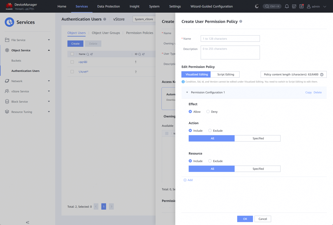
Step 6 Click OK on the Create User Permission Policy and Create Object User pages in sequence to complete the object user configuration.
—-End

To connect to the OceanProtect Backup Storage through HTTPS, you need to issue and import a native S3 authentication certificate. For details, see How Do I Issue and Import a Native S3 Authentication Certificate?.
4.5.3 Configuration for Data Protector Integration
This section describes how to configure a bucket of the OceanProtect Backup Storage as a repository on the Data Protector GUI as well as how to use the repository.
Step 1 On the Data Protector console, choose Devices & Media > Environment > Devices. Right-click Devices, choose Add Device from the shortcut menu, and create a device.
Step 2 On the Add Device page, customize Device Name, set Device Type to Backup To Disk, set Interface Type to Cloud (Amazon S3 API compatible target), retain the default value for Management Console URL, and click Next.
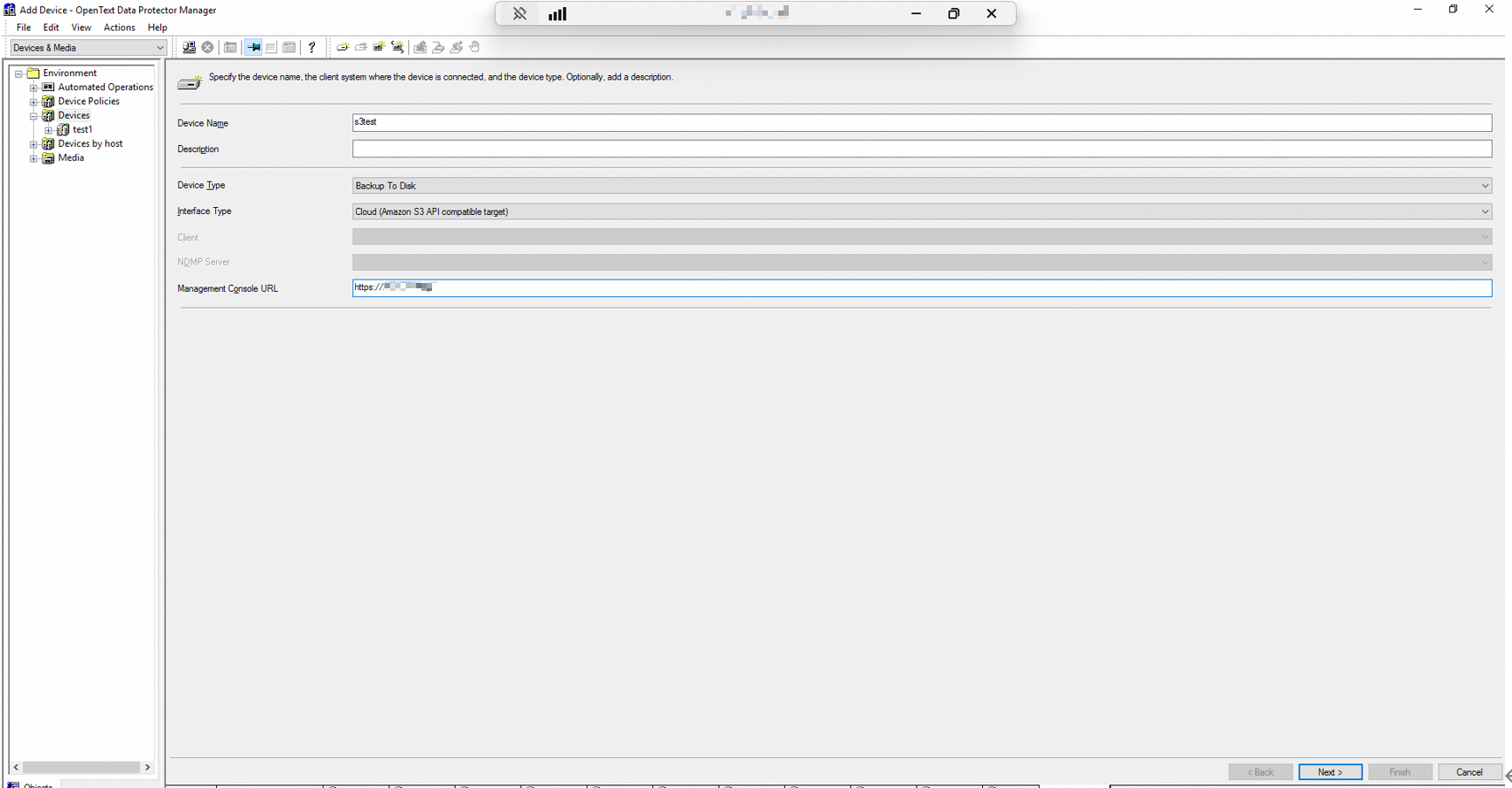
Step 3 Set S3 Target Type to Ceph / Scality, set S3 Target Gateway URL http(s)://<host>(:<port>)/ to the IP address or domain name of the object storage logical port created in 4.5.2.1 Network Configuration as prompted, and set Access Key ID and Secret Access Key to the AK and SK created in 4.5.2.3 Object User Configuration.
Step 4 Click Select / Create Bucket next to the Bucket area, choose Select existing bucket, select the bucket created in 4.5.2.2 Bucket Configuration, and click OK.
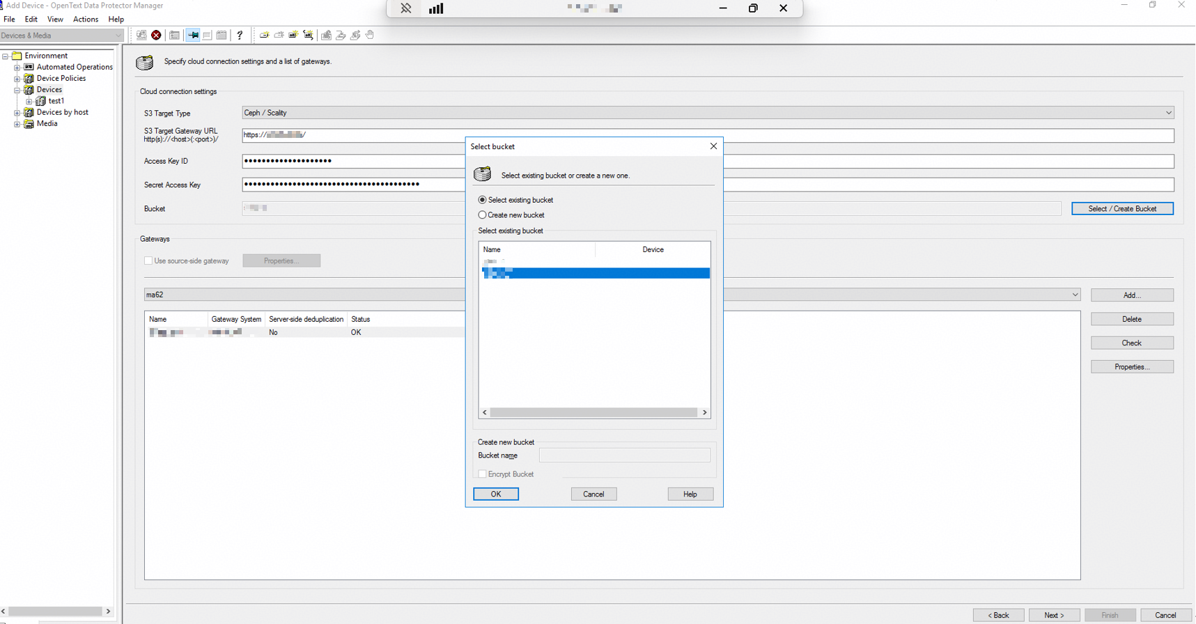
Step 5 In the Gateways area, select the host used to access the S3 bucket and click Add. In the dialog box that is displayed, retain the default values for all parameters, click OK to close the dialog box, and click Next.
Step 6 On the summary page, click Finish.
Step 7 For details about how to use the device when you create a backup job, see 4.4.5.5 Configuring a Backup Job.
Step 8 Disable the encryption and compression functions of the Data Protector backup software and modify the related concurrency and buffer configurations.
- On the Cell Manager server, find the omnirc file (hidden file) in the C:\Program Files\OmniBack\ directory.
- Add the following content to the file:
OB2UNSECURE=1
OB2_CLOUDDEV_NOENCRYPT=1
OB2_VEAGENT_VCENTER_CONNECTION_LIMIT=50
OB2_VEAGENT_BACKUP_DISK_BUFFER_SIZE=256
OB2_VEAGENT_DISK_CONCURRENCY=50
OB2_CLOUDDEV_NOCOMPRESS=1
3. Copy the file to the following directories on the Cell Manager and MA server:
C:\ProgramData\OmniBack\server\db80 (If the MA server does not have this directory, you do not need to copy the file.)
C:\ProgramData\OmniBack\
C:\Program Files\OmniBack\
4.6 Data Protector Software–based Replication and Tiering
This section describes how to use the Object copy function of the Data Protector backup software to replicate and tier backup copies.
In this section, the OceanProtect Backup Storage is used only as NAS storage or S3 object storage and does not provide storage-layer replication and tiering capabilities.
4.6.1 Function Description
The Object copy function allows you to create multiple copies of the same backup file and replicate them to other storage devices. The content of the backup copy file is the same as that of the primary backup file. Therefore, you can directly restore required data using the backup copy file in the event of a disaster. For details, see the OpenText Data Protector official documentation.
The Object copy function creates the same backup copy in another storage device based on backup jobs and sets different retention policies.
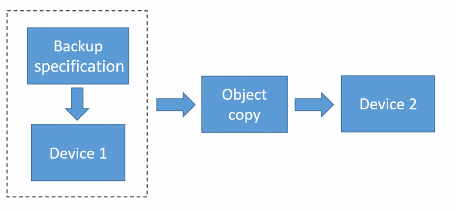
This job is classified as a replication or tiering operation in different networking environments, regardless of the protocol for integration with the OceanProtect Backup Storage.
4.6.2 Configuration Example
Prerequisites
The file system or bucket of the OceanProtect Backup Storage has been integrated with Data Protector, and the corresponding Data Protector storage device and backup job have been configured.
The media for replication or tiered archiving has been integrated with Data Protector, and the corresponding Data Protector storage device has been configured.
Object Copy Configuration
Step 1 On the Data Protector console, choose Object Operation > Copy > Object copy > Automated > Post Backup, right-click Post Backup for new creation, select the backup job for replication, and click Next.
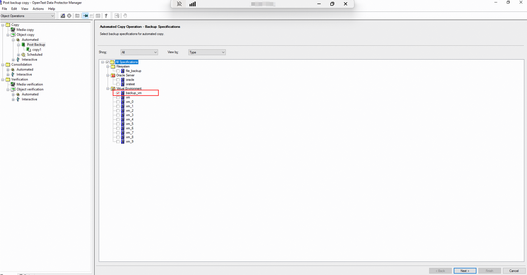
Step 2 On the Copy Specifications page, select All Specification (you can expand and select specific items as required) and click Next.
Step 3 On the Object Filter page, set filter criteria based on service requirements and click Next.
Step 4 On the Consolidation Specifications page, select All Specification (you can expand and select specific items as required) and click Next.
Step 5 On the Library Filter page, configure filter criteria to filter out storage devices that have been configured in the backup software. Generally, you do not need to filter out storage devices. Select All libraries and click Next.
Step 6 On the Destination Devices page, select Show all, select a device as the destination storage for replication or tiering, and click Next.
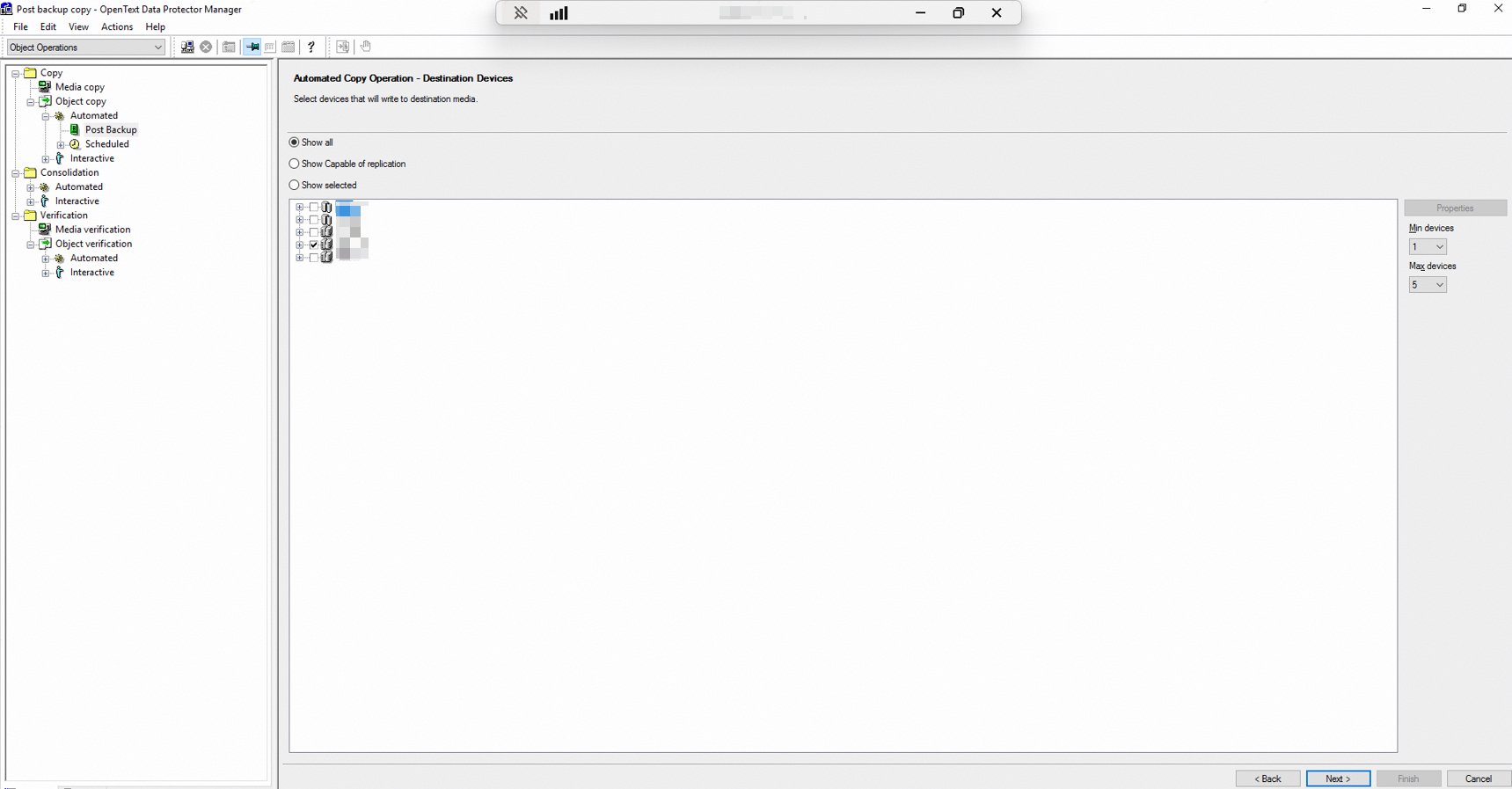
Step 7 Click Finish. The Object copy job configuration is complete.
4.7 Best Practice Verification
4.7.1 Backup Performance Using a Single MA
This solution uses a typical server (CPU: Intel(R) Xeon(R) Silver 4208; memory: 32 GB) to test VMware VM backup performance using a single MA. The test information is as follows:
Test scenario:
- Production environment: A single MA is used to back up 10 VMs of 2 ESXi hosts. Each VM is configured with 6 disks (1 system disk and 5 data disks). A total of 600 GB data is preset on the data disks.
- Backup environment: OceanProtect X8000 (all-flash form). A file system is created and connected to one MA through DataTurbo over an IP network.
- Test model: Test the initial, second, and third full backups with 5% data changing each time. Table 4-4 shows bandwidth performance test results with a single MA used.
Table 4-4 Backup bandwidth performance test results when a TCP network is used
Compression Mode | Backup Type | Peak Backup Bandwidth (GB/s) | Backup Data Volume (GB) | Backup Duration (Minutes) | Average Backup Bandwidth (GB/s) |
|---|---|---|---|---|---|
High performance mode | Initial backup | 1.815 | 6508 | 86 | 1.261 |
Second backup | 1.954 | 6508 | 82 | 1.323 | |
Third backup | 2.01 | 6508 | 72 | 1.506 | |
High reduction ratio mode | Initial backup | 1.409 | 6508 | 97 | 1.118 |
Second backup | 1.97 | 6508 | 76 | 1.427 | |
Third backup | 2.01 | 6508 | 75 | 1.446 |

The high performance mode and high reduction ratio mode in the table are described as follows:
- High performance mode: When the storage pool compression mode is set to high performance mode, set the file system application type to Performance_Prioritized_Mode_enhanced.
- High reduction ratio mode: When the storage pool compression mode is set to high reduction ratio mode, set the file system application type to Reduction_Prioritized_Mode_enhanced.
4.7.2 Restoration Performance Using a Single MA
4.7.2 Restoration Performance Using a Single MA shows the test results of using a single MA server to restore two VMware VMs.
Table 4-5 Restoration bandwidth performance test results when TCP networking is used
Compression Mode | VMware VM Quantity | Peak Restoration Bandwidth (MB/s) | Restored Data Volume (GB) | Restoration Duration (Minutes) | Average Restoration Bandwidth (MB/s) |
|---|---|---|---|---|---|
High performance mode | 2 | 299 | 1300 | 307 | 72 |
High reduction ratio mode | 2 | 307 | 1300 | 220 | 100 |
4.7.3 Backup Performance When the S3 Protocol Is Used for Integration
In the test solution of this section, two hosts are used to test the performance of VM backup. For details about the networking, see 4.5.1 Solution Networking. The detailed performance test scenario is as follows:
- Production environment: Two ESXi hosts are used, and 100 GB data is preset on each VM of the ESXi hosts.
- Backup environment: Two physical hosts are used. The CPU is Intel(R) Xeon(R) Platinum 8260 CPU @ 2.40 GHz, and the memory is 64 GB × 8. VMs are backed up in SAN transmission mode. OceanProtect E8000 all-flash storage is used, and a storage pool with a high reduction ratio is used to create two buckets.
- Data Protector planning:
- Device: Each bucket is configured as an independent device. A total of two devices are configured.
- Backup job configuration: Two backup jobs are configured to evenly back up all target VMs to two different devices separately.
- Test model: The full backup performance is tested.
Table 4-6 describes the test result.
Table 4-6 Performance test result for Data Protector S3 integration in high backup bandwidth scenarios
S3 Protocol | Host Quantity | Peak Backup Bandwidth (GB/s) | Backup Data Volume (TB) | Backup Duration (min) | Average Backup Bandwidth (GB/s) |
|---|---|---|---|---|---|
HTTP | 1 | 1.09 | 2.5 | 55 | 0.78 |
2 | 2.06 | 5.1 | 52 | 1.67 | |
HTTPS | 1 | 0.9 | 3 | 68 | 0.75 |
2 | 1.66 | 6 | 69 | 1.48 |

The backup duration is the duration from when the backup starts to when backup of the last VM ends. The restoration duration is the duration from when the restoration starts to when restoration of the last VM is complete.
